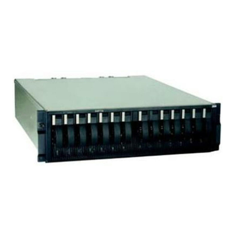
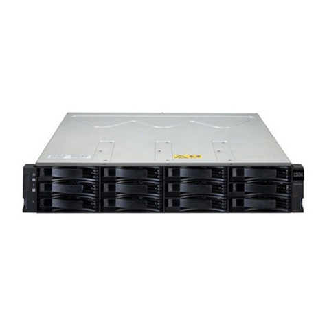
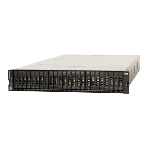
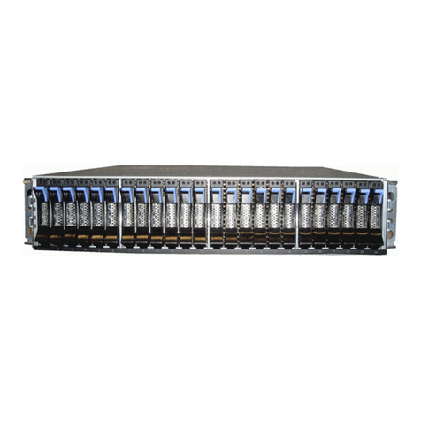
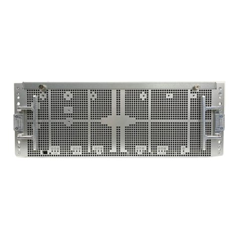
IBM Netfinity FAStT500 User manual


Netfinity FAStT500 RAID Controller Enclosure Unit
Installation Guide

First Edition (April 2000)
INTERNATIONAL BUSINESS MACHINES CORPORATION PROVIDES THIS PUBLICATION “AS IS” WITHOUT WAR-
RANTY OF ANY KIND, EITHER EXPRESS OR IMPLIED, INCLUDING, BUT NOT LIMITED TO, THE IMPLIED WAR-
RANTIES OF MERCHANTABILITY OR FITNESS FOR A PARTICULAR PURPOSE. Some jurisdictions do not allow
disclaimer of express or implied warranties in certain transactions, therefore, this statement may not apply to you.
This publication could include technical inaccuracies or typographical errors. Changes are periodically made to the information
herein; these changes will be incorporated in new editions of the publication. IBM may make improvements and/or changes in the
product(s) and/or the program(s) described in this publication at any time.
This publication was developed for products and services offered in the United States of America and the United Kingdom. It is
possible that this publication may contain references to, or information about, IBM products (machines and programs), program-
ming, or services that are not announced in your country. Such references or information must not be construed to mean that IBM
intends to announce such IBM products, programming or services in your country.
Requests for technical information about IBM products should be made to your IBM reseller or IBM marketing representative.
No part of this publication may be reproduced or distributed in any form or by any means without prior permission in writing from
the International Business Machines Corporation.
© Copyright International Business Machines Corporation 2000. All rights reserved.
Note to U.S. Government Users—Documentation related to restricted rights—Use, duplication or disclosure is subject to restric-
tions set forth in GSA ADP Schedule Contract with IBM Corp.
Before using this information and the product it supports, be sure to read the general information under "Appendix.
Product warranties and notices" on page 51.

©Copyright IBM Corp. 2000 iii
Contents
Figures . . . . . . . . . . . . . . . . . . . . . . . . . . . . . . . . . . . . . . . . . . . . . . . . . . . . . . . . . . . . . . . . v
Safety statement . . . . . . . . . . . . . . . . . . . . . . . . . . . . . . . . . . . . . . . . . . . . . . . . . . . . . . vii
Electrical safety . . . . . . . . . . . . . . . . . . . . . . . . . . . . . . . . . . . . . . . . . . . . . . . . . . . . . . . . . . . .ix
Class 1 laser statement . . . . . . . . . . . . . . . . . . . . . . . . . . . . . . . . . . . . . . . . . . . . . . . . . . . . . . . x
About this book. . . . . . . . . . . . . . . . . . . . . . . . . . . . . . . . . . . . . . . . . . . . . . . . . . . . . . . . xi
How this book is organized . . . . . . . . . . . . . . . . . . . . . . . . . . . . . . . . . . . . . . . . . . . . . . . . . . .xi
Notices used in this book . . . . . . . . . . . . . . . . . . . . . . . . . . . . . . . . . . . . . . . . . . . . . . . . . . . . .xi
Related publications . . . . . . . . . . . . . . . . . . . . . . . . . . . . . . . . . . . . . . . . . . . . . . . . . . . . . . . . xii
Chapter 1. Getting started . . . . . . . . . . . . . . . . . . . . . . . . . . . . . . . . . . . . . . . . . . . . . . . . 1
Controller unit components . . . . . . . . . . . . . . . . . . . . . . . . . . . . . . . . . . . . . . . . . . . . . . . . . . . 3
Operating specifications . . . . . . . . . . . . . . . . . . . . . . . . . . . . . . . . . . . . . . . . . . . . . . . . . . . . . . 5
Preparing for installation . . . . . . . . . . . . . . . . . . . . . . . . . . . . . . . . . . . . . . . . . . . . . . . . . . . . . 6
Handling static sensitive devices . . . . . . . . . . . . . . . . . . . . . . . . . . . . . . . . . . . . . . . . . . . . . . 10
Preparing the site . . . . . . . . . . . . . . . . . . . . . . . . . . . . . . . . . . . . . . . . . . . . . . . . . . . . . . . . . . 10
Floor space . . . . . . . . . . . . . . . . . . . . . . . . . . . . . . . . . . . . . . . . . . . . . . . . . . . . . . . . . . . . . 10
Weight . . . . . . . . . . . . . . . . . . . . . . . . . . . . . . . . . . . . . . . . . . . . . . . . . . . . . . . . . . . . . . . . 10
Preparing the rack . . . . . . . . . . . . . . . . . . . . . . . . . . . . . . . . . . . . . . . . . . . . . . . . . . . . . . . . . 10
Preparing the drive enclosures . . . . . . . . . . . . . . . . . . . . . . . . . . . . . . . . . . . . . . . . . . . . . . . . 11
Preparing the controller unit . . . . . . . . . . . . . . . . . . . . . . . . . . . . . . . . . . . . . . . . . . . . . . . . . 12
Installing the support rails . . . . . . . . . . . . . . . . . . . . . . . . . . . . . . . . . . . . . . . . . . . . . . . . . . . 14
Installing the controller unit in the rack . . . . . . . . . . . . . . . . . . . . . . . . . . . . . . . . . . . . . . . . . 17
Installing additional cache memory in a controller . . . . . . . . . . . . . . . . . . . . . . . . . . . . . . . . 19

iv IBM Netfinity FAStT500 RAID Controller Enclosure Unit Installation Guide
Chapter 2. Connecting the controller unit to the loop. . . . . . . . . . . . . . . . . . . . . . . . . 23
Mini-hub interface connections . . . . . . . . . . . . . . . . . . . . . . . . . . . . . . . . . . . . . . . . . . . . . . . .23
Controller unit interface ports . . . . . . . . . . . . . . . . . . . . . . . . . . . . . . . . . . . . . . . . . . . . . . . . .24
Host interface ports . . . . . . . . . . . . . . . . . . . . . . . . . . . . . . . . . . . . . . . . . . . . . . . . . . . . . . .24
Drive mini-hubs . . . . . . . . . . . . . . . . . . . . . . . . . . . . . . . . . . . . . . . . . . . . . . . . . . . . . . . . .25
Ethernet and RS-232 ports . . . . . . . . . . . . . . . . . . . . . . . . . . . . . . . . . . . . . . . . . . . . . . . . .26
Installing GBICs and fiber-optic cables . . . . . . . . . . . . . . . . . . . . . . . . . . . . . . . . . . . . . . . . .27
Controller unit and drive enclosure cabling overview . . . . . . . . . . . . . . . . . . . . . . . . . . . . . .30
Configuring the drive loops . . . . . . . . . . . . . . . . . . . . . . . . . . . . . . . . . . . . . . . . . . . . . . . . . .31
Connecting drive cables to the controller unit . . . . . . . . . . . . . . . . . . . . . . . . . . . . . . . . . . . .33
Connecting hosts directly to the controller unit . . . . . . . . . . . . . . . . . . . . . . . . . . . . . . . . . . .35
Connecting hosts using external devices . . . . . . . . . . . . . . . . . . . . . . . . . . . . . . . . . . . . . . . . .36
Connecting secondary interface cables . . . . . . . . . . . . . . . . . . . . . . . . . . . . . . . . . . . . . . . . . .39
Chapter 3. Starting the controller unit. . . . . . . . . . . . . . . . . . . . . . . . . . . . . . . . . . . . . 41
Turning on the power . . . . . . . . . . . . . . . . . . . . . . . . . . . . . . . . . . . . . . . . . . . . . . . . . . . . . . .41
Turning off the power . . . . . . . . . . . . . . . . . . . . . . . . . . . . . . . . . . . . . . . . . . . . . . . . . . . . . .42
Turning on the controller unit alarm . . . . . . . . . . . . . . . . . . . . . . . . . . . . . . . . . . . . . . . . . . . .43
Controller unit indicator lights . . . . . . . . . . . . . . . . . . . . . . . . . . . . . . . . . . . . . . . . . . . . . . . .44
Completing the installation . . . . . . . . . . . . . . . . . . . . . . . . . . . . . . . . . . . . . . . . . . . . . . . . . . .48
Chapter 4. Getting help, service, and information . . . . . . . . . . . . . . . . . . . . . . . . . . . 49
Appendix. Product warranties and notices . . . . . . . . . . . . . . . . . . . . . . . . . . . . . . . . . 51
Warranty statements . . . . . . . . . . . . . . . . . . . . . . . . . . . . . . . . . . . . . . . . . . . . . . . . . . . . . . . .51
Notices . . . . . . . . . . . . . . . . . . . . . . . . . . . . . . . . . . . . . . . . . . . . . . . . . . . . . . . . . . . . . . . . . . .59
Trademarks . . . . . . . . . . . . . . . . . . . . . . . . . . . . . . . . . . . . . . . . . . . . . . . . . . . . . . . . . . . . .59
Electronic emissions statements . . . . . . . . . . . . . . . . . . . . . . . . . . . . . . . . . . . . . . . . . . . . . . .60
Federal Communications Commission (FCC) Statement . . . . . . . . . . . . . . . . . . . . . . . . . .60
Industry Canada Class A emission compliance statement . . . . . . . . . . . . . . . . . . . . . . . . .60
United Kingdom telecommunications safety requirements . . . . . . . . . . . . . . . . . . . . . . . .60
European community directive conformance statement . . . . . . . . . . . . . . . . . . . . . . . . . . .60
Australia and New Zealand Class A statement . . . . . . . . . . . . . . . . . . . . . . . . . . . . . . . . . .61
Taiwanese electromagnetic interference (EMI) statement . . . . . . . . . . . . . . . . . . . . . . . . .61
Power cords . . . . . . . . . . . . . . . . . . . . . . . . . . . . . . . . . . . . . . . . . . . . . . . . . . . . . . . . . . . . . . .61
vi IBM Netfinity FAStT500 RAID Controller Enclosure Unit Installation Guide

©Copyright IBM Corp. 2000 v
Figures
Figure 1. Netfinity FAStT500 RAID Controller Enclosure Unit . . . . . . . . . . . . . . . . . . . . . . . . . . 2
Figure 2. Netfinity FAStT500 RAID Controller Enclosure Unit –front view . . . . . . . . . . . . . . . . 4
Figure 3. Netfinity FAStT500 RAID Controller Enclosure Unit –back view . . . . . . . . . . . . . . . . 4
Figure 4. Host-agent managed storage subsystems. . . . . . . . . . . . . . . . . . . . . . . . . . . . . . . . . . . . . 7
Figure 5. Directly managed storage subsystems . . . . . . . . . . . . . . . . . . . . . . . . . . . . . . . . . . . . . . . 7
Figure 6. Installing the storage subsystem on a Fibre Channel network. . . . . . . . . . . . . . . . . . . . . 9
Figure 7. Removing the controller unit bezel . . . . . . . . . . . . . . . . . . . . . . . . . . . . . . . . . . . . . . . . 12
Figure 8. Removing and replacing the controller fan and controllers. . . . . . . . . . . . . . . . . . . . . . 13
Figure 9. Removing and replacing the battery . . . . . . . . . . . . . . . . . . . . . . . . . . . . . . . . . . . . . . . 13
Figure 10. Removing and replacing the power supplies and fan and communications module . . 14
Figure 11. Removing and replacing the mini-hub. . . . . . . . . . . . . . . . . . . . . . . . . . . . . . . . . . . . . 14
Figure 12. Replacing the controller unit bezel . . . . . . . . . . . . . . . . . . . . . . . . . . . . . . . . . . . . . . . 18
Figure 13. Mini-hub interface connections . . . . . . . . . . . . . . . . . . . . . . . . . . . . . . . . . . . . . . . . . . 23
Figure 14. Controller unit interface ports . . . . . . . . . . . . . . . . . . . . . . . . . . . . . . . . . . . . . . . . . . . 24
Figure 15. Controller unit host mini-hubs . . . . . . . . . . . . . . . . . . . . . . . . . . . . . . . . . . . . . . . . . . 25
Figure 16. Controller unit drive mini-hubs . . . . . . . . . . . . . . . . . . . . . . . . . . . . . . . . . . . . . . . . . . 26
Figure 17. Controller unit Ethernet and RS-232 ports. . . . . . . . . . . . . . . . . . . . . . . . . . . . . . . . . . 26
Figure 18. Redundant drive loop cabling overview . . . . . . . . . . . . . . . . . . . . . . . . . . . . . . . . . . . 30
Figure 19. Example of connecting two drive enclosures into a redundant drive loop . . . . . . . . . 31
Figure 20. Connecting a second redundant drive loop . . . . . . . . . . . . . . . . . . . . . . . . . . . . . . . . . 32
Figure 21. Cabling redundant drive enclosure loops to the controller unit. . . . . . . . . . . . . . . . . . 33
Figure 22. Two redundant drive enclosure groups . . . . . . . . . . . . . . . . . . . . . . . . . . . . . . . . . . . . 34
Figure 23. Connecting hosts directly to the controller . . . . . . . . . . . . . . . . . . . . . . . . . . . . . . . . . 36
Figure 24. Using managed hubs to connect a host . . . . . . . . . . . . . . . . . . . . . . . . . . . . . . . . . . . . 37
Figure 25. Using managed hubs to connect multiple hosts. . . . . . . . . . . . . . . . . . . . . . . . . . . . . . 38
Figure 26. Connecting Ethernet and RS-232 interface cables. . . . . . . . . . . . . . . . . . . . . . . . . . . . 39

vi IBM Netfinity FAStT500 RAID Controller Enclosure Unit Installation Guide
Figure 27. Connecting the power cords and turning on and off the power . . . . . . . . . . . . . . . . . 41
Figure 28. Controller unit alarm switch . . . . . . . . . . . . . . . . . . . . . . . . . . . . . . . . . . . . . . . . . . . . 43
Figure 29. Controller indicator lights —front view. . . . . . . . . . . . . . . . . . . . . . . . . . . . . . . . . . . 44
Figure 30. Controller fan indicator lights —front view. . . . . . . . . . . . . . . . . . . . . . . . . . . . . . . . 45
Figure 31. Battery indicator lights —front view . . . . . . . . . . . . . . . . . . . . . . . . . . . . . . . . . . . . . 46
Figure 32. Controller unit indicator lights —back view . . . . . . . . . . . . . . . . . . . . . . . . . . . . . . . 46
Figure 33. Mini-hub indicator lights. . . . . . . . . . . . . . . . . . . . . . . . . . . . . . . . . . . . . . . . . . . . . . . 47

©Copyright IBM Corp. 2000 vii
Safety statement
Before installing this product, read the Safety Information book.
Antes de instalar este produto, leia o Manual de Informações sobre Segurança.
Læs hæftet med sikkerhedsforskrifter, før du installerer dette produkt.
Lue Safety Information -kirjanen, ennen kuin asennat tämän tuotteen.
Avant de procéder à l'installation de ce produit, lisez le manuel Safety Information.
Vor Beginn der Installation die Broschüre mit Sicherheitshinweisen lesen.
Prima di installare questo prodotto, leggere l'opuscolo contenente le informazioni sulla sicurezza.
Lees voordat u dit product installeert eerst het boekje met veiligheidsvoorschriften.
Les heftet om sikkerhetsinformasjon (Safety Information) før du installerer dette produktet.
Antes de instalar este produto, leia o folheto Informações sobre Segurança.
Pred instalacítohoto produktu si prectete prírucku bezpecnostních instrukcí.
Przed zainstalowaniem tego produktu należy przeczytać broszurę Informacje Dotyczące
Bez
p
ieczeństwa.

viii IBM Netfinity FAStT500 RAID Controller Enclosure Unit Installation Guide
Antes de instalar este producto, lea la Información de Seguridad.
Läs säkerhetsinformationen innan du installerar den här produkten.
Перед установкой продукта прочтите брошюру по технике безопасности
(Safety Inf rmati n).
Pred inštaláciou tohto produktu si pre ítajte Informa núbrožúrku o bezpe nosti.
Preden namestite ta izdelek, preberite knjižico Varnostne informacije.
Installálás el tt olvassa el a Biztonsági el írások kézikönyvét !

Safety statement ix
Electrical safety
To Connect:
1. Turn everything OFF.
2. First, attach all cables to devices.
3. Attach signal cables to connectors.
4. Attach power cords to outlet.
5. Turn device ON.
To Disconnect:
1. Turn everything OFF.
2. First, remove power cords from outlet.
3. Remove signal cables from connectors.
4. Remove all cables from devices.
1
DANGER
Electrical current from power, telephone, and
communication cables is hazardous.
To avoid a shock hazard:
–Do not connect or disconnect any cables or perform
installation, maintenance, or reconfiguration of this
product during an electrical storm.
–Connect all power cords to a properly wired and
grounded electrical outlet.
–Connect to properly wired outlets any equipment
that will be attached to this product.
–When possible, use one hand only to connect or
disconnect signal cables.
–Never turn on any equipment when there is evidence
of fire, water, or structural damage.
–Disconnect the attached power cords,
telecommunications systems, networks, and modems
before you open the device covers, unless instructed
otherwise in the installation and configuration
procedures.
–Connect and disconnect cables as described in the
following table when installing, moving, or opening
covers on this product or attached devices.

x IBM Netfinity FAStT500 RAID Controller Enclosure Unit Installation Guide
CAUTION:
When laser products (such as CD-ROMs, DVD drives, fiber optic devices, or
transmitters) are installed, note the following:
– Do not remove the covers. Removing the covers of the laser product could result
in exposure to hazardous laser radiation. There are no serviceable parts inside the
device.
– Use of controls or adjustments or performance of procedures other than those
specified herein might result in hazardous radiation exposure.
Class 1 laser statement
DANGER
Some laser products contain an embedded Class 3A or Class 3B
laser diode. Note the following.
Laser radiation when open. Do not stare into the beam, do not view
directly with optical instruments, and avoid direct exposure to the
beam.
3
Class 1 Laser Product
Laser Klasse 1
Laser Klass 1
Luokan 1 Laserlaite
Appareil A Laser de Classe 1
IEC 825-1:1993 CENELEC EN 60 825
`

©Copyright IBM Corp. 2000 xi
About this book
This book provides instructions for setting up, installing, and connecting your
IBM®Netfinity®FAStT500 RAID Controller Enclosure Unit. This Installation Guide is
intended for system operators and service technicians who have extensive knowledge of
Fibre Channel and network technology.
How this book is organized
"Chapter 1. Getting started" introduces the controller enclosure unit and contains setup
instructions. This chapter also includes an overview of the controller enclosure unit
features and components.
"Chapter 2. Connecting the controller unit to the loop" provides descriptions of the
components that connect the controller enclosure unit to the network, instructions for
installing the interface cable, and instructions for completing the installation.
"Chapter 3. Starting the controller unit" provides information about connecting the power
cords, turning on and off the power, checking the indicator lights, and completing the
installation.
"Chapter 4. Getting help, service, and information" describes how to obtain help, service,
and information about IBM products.
"Appendix. Product warranties and notices" provides warranty statements and product
notices.
Notices used in this book
This book contains notices to highlight information or provide safety information:
•Note
These notices provide important tips, guidance, or advice.
•Attention
These notices indicate possible damage to programs, devices, or data. An attention
notice is placed just before the instruction or situation in which damage could occur.

xii IBM Netfinity FAStT500 RAID Controller Enclosure Unit Installation Guide
•Caution
These notices indicate situations that can be potentially hazardous to you. A caution
notice is placed just before descriptions of potentially hazardous procedure steps or
situations.
•Danger
These notices indicate situations that are potential lethal or extremely hazardous to
you. A danger notice is placed just before descriptions of potentially lethal or
extremely hazardous procedure steps or situations.
Related publications
The following publications are available in Adobe®Acrobat®Portable Document Format
(PDF) on the IBM Netfinity FAStT Storage Manager CD and on the World Wide Web at
http://www.ibm.com/pc/support/
Note: The items denoted by an asterisk (*) in the list indicate publications that are printed
and come with the IBM Netfinity FAStT500 RAID Controller Enclosure Unit.
IBM Netfinity FAStT500 RAID Controller Enclosure Unit Installation Guide
(this book)*
•IBM Netfinity FAStT500 RAID Controller Enclosure Unit User’s Reference
•IBM Netfinity FAStT Storage Manager for Windows NT Installation and Support
Guide*.
•IBM Netfinity Fibre Channel Storage Manager Concepts Guide
Additional publications are available for purchase from IBM. For a list of publications
available in your country:
•In the U.S. and Puerto Rico, call 1-800-426-7282.
•In the United Kingdom, call 01705-565000 or 0161-9056001.
•In Canada, call 1-800-465-1234.
•In other countries, contact the IBM support organization that services your area, your
IBM marketing representative, or your IBM reseller.

©Copyright IBM Corp. 2000 1
Chapter 1. Getting started
Thank you for purchasing an IBM®Netfinity®FAStT product. Netfinity FAStT
(Fibre Array Storage Technology) solutions are designed to support the large and growing
data storage requirements of business-critical applications. These scalable Netfinity
FAStT solutions offer you data access and protection to meet your existing enterprise
storage requirements and prepare for the future.
The Netfinity FAStT500 RAID Controller Enclosure Unit (referred to throughout this
book as controller unit) is a high-performance unit that provides dual, redundant
controllers with Fibre Channel interfaces to both the host and drive channels. The
controller unit has redundant cooling, redundant power, and battery backup of the
controller cache.
Designed to provide maximum host and drive side redundancy, the controller unit
supports direct attachment of up to four hosts containing two host adapters each. Using
external managed hubs and switches in conjunction with the RAID controller unit, you
can build even larger configurations. (Throughout this book, the use of hub or external hub
refers to a managed hub.)
Fibre Channel is a new technology, similar to a high-speed network, that you can use to
connect large amounts of disk storage to a server or cluster of servers. Fibre Channel
technology supports increased performance, scalability, availability, and distance for
attaching storage subsystems to network servers. The controller unit provides for the
attachment of Fibre Channel disk drives to give superior performance and redundancy.
Fibre Channel technology supports applications that require large amounts of disk storage
shared by two or more servers. With Fibre Channel, you can see a higher throughput rate
over longer distances than is possible with small computer system interface (SCSI) or with
Serial Storage Architecture (SSA) technology.
This chapter provides descriptions of the primary components of the controller unit and
contains setup instructions. The controller unit is used with rack-mounted drive enclosures
(also referred to as expansion units) for Fibre Channel.

2 IBM Netfinity FAStT500 RAID Controller Enclosure Unit Installation Guide
The following figure shows the Netfinity FAStT500 RAID Controller Enclosure Unit.
Figure 1. Netfinity FAStT500 RAID Controller Enclosure Unit
The controller unit comes with the following items:
Hardware:
•Two RAID controllers
•Two power supplies
•Battery
•Two host mini-hubs and two drive mini-hubs
•Two power cords or two high voltage rack jumpers
•One rack-mounting hardware kit:
•Two rails (right and left)
•Eight black M6 hex-head screws
•Eight clip nuts
•Eight cage nuts

Chapter 1. Getting started 3
Software and documentation:
•IBM Netfinity FAStT Storage Manager Version 7.01 CD including:
•Netfinity FAStT Storage Manager 7.01
•Publications and online help in Adobe Acrobat PDF format
For a listof available Netfinity FAStT500 publications, see "Related publications" on page
xii.
•Rack Mounting Assembly including:
•Rack Mounting Installation Instructions
•Rack Mounting Template
•White tape dots
•Fibre Channel Cabling Instructions
Controller unit components
The controller unit has the following removable components, called customer replaceable
units (CRUs). All CRUs are accessible from either the front or back of the controller unit.
•Bezel (front cover)
•Controller fan
•Battery
•Controller (two each)
•Power supply (two each)
•Host mini-hub (comes with two, four maximum)
•Drive mini-hub (comes with two, four maximum)
•Fan and communications module

4 IBM Netfinity FAStT500 RAID Controller Enclosure Unit Installation Guide
The following figure shows the controller unit front view.
Figure 2. Netfinity FAStT500 RAID Controller Enclosure Unit –front view
The following figure shows the controller unit back view.
Figure 3. Netfinity FAStT500 RAID Controller Enclosure Unit –back view
Removable
bezel
Controller
fan Controllers
Battery
Host mini-hubs Fan and communications
module
Power supply
Drive mini-hubs
Power supply
Table of contents
Other IBM Enclosure manuals

IBM
IBM 2104 DL1 User manual

IBM
IBM TotalStorage FAStT EXP700 Operating instructions

IBM
IBM 2104 Model DS4 User manual

IBM
IBM Small J10 Series User manual

IBM
IBM 7226 User manual

IBM
IBM EXP15 User manual

IBM
IBM 7383 Installation and maintenance instructions

IBM
IBM Elastic Storage System 5147-102 User manual

IBM
IBM Medium J11 Instruction Manual

IBM
IBM 4 U User manual