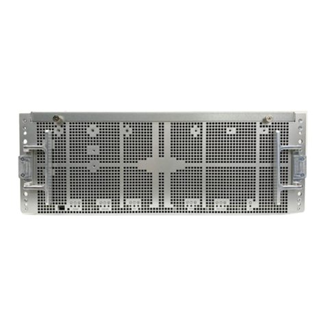
IBM Elastic Storage System 5000 Series Installation instructions

IBM Elastic Storage System 5000
Version 6.0.1
Model 092 Hardware Guide
IBM
SC28-3135-00

Note
Before using this guide and the product it supports, read the information in Chapter 1, “Notices,” on
page 1.
This edition applies to version 6 release 0 modication 1 of the following product and to all subsequent releases and
modications until otherwise indicated in new editions:
• IBM Spectrum® Scale Data Management Edition for IBM ESS (product number 5765-DME)
• IBM Spectrum Scale Data Access Edition for IBM ESS (product number 5765-DAE)
IBM welcomes your comments; see the topic “How to submit your comments” on page xiii. When you send information
to IBM, you grant IBM a nonexclusive right to use or distribute the information in any way it believes appropriate without
incurring any obligation to you.
© Copyright International Business Machines Corporation 2020.
US Government Users Restricted Rights – Use, duplication or disclosure restricted by GSA ADP Schedule Contract with
IBM Corp.

Contents
Figures.................................................................................................................. v
Tables.................................................................................................................. ix
About this information.......................................................................................... xi
Who should read this information...............................................................................................................xi
IBM Elastic Storage System information units...........................................................................................xi
Related information....................................................................................................................................xii
Conventions used in this information........................................................................................................ xii
How to submit your comments................................................................................................................. xiii
Chapter 1. Notices................................................................................................. 1
Trademarks.................................................................................................................................................. 2
Homologation statement.............................................................................................................................3
Safety and environmental notices...............................................................................................................3
Safety notices and labels....................................................................................................................... 3
Special caution and safety notices........................................................................................................ 8
Environmental notices......................................................................................................................... 11
Electromagnetic compatibility notices......................................................................................................11
Canada Notice...................................................................................................................................... 11
European Community and Morocco Notice.........................................................................................11
Germany Notice....................................................................................................................................11
Japan Electronics and Information Technology Industries Association (JEITA) Notice...................12
Japan Voluntary Control Council for Interference (VCCI) Notice ...................................................... 13
Korea Notice.........................................................................................................................................13
People's Republic of China Notice.......................................................................................................13
Russia Notice........................................................................................................................................13
Taiwan Notice.......................................................................................................................................14
United States Federal Communications Commission (FCC) Notice................................................... 14
Chapter 2. Weight considerations: Model 092 expansion enclosure.......................15
Chapter 3. System overview.................................................................................19
Model 092 expansion enclosure features.................................................................................................19
Chapter 4. Planning for hardware.........................................................................23
Planning for site preparation..................................................................................................................... 23
Site preparation and physical planning............................................................................................... 23
Planning for hardware installation............................................................................................................ 23
Planning for racks.................................................................................................................................23
Reviewing Model 092 expansion enclosure location guidelines........................................................ 24
Planning for power for Model 092 expansion enclosure.................................................................... 24
Physical installation planning....................................................................................................................25
Operating environment........................................................................................................................ 25
Model 092 expansion enclosure requirements...................................................................................26
IP address allocation and usage..........................................................................................................33
Planning for high availability......................................................................................................................33
Storage conguration planning................................................................................................................. 33
Planning the network and storage network.............................................................................................. 33
iii
Planning for cables.................................................................................................................................... 33
Connections for Model 092 expansion enclosure...............................................................................33
Supported environment.............................................................................................................................38
Chapter 5. Installing Model 092 expansion enclosure........................................... 39
Checklist: Unpacking and installing Model 092 expansion enclosure.....................................................39
External parts of the Model 092 expansion enclosure.............................................................................42
Removing the top cover.............................................................................................................................44
Installing or replacing the support rails (IBM SSR task).......................................................................... 45
Installing or replacing the fascia............................................................................................................... 48
Installing or replacing a drive....................................................................................................................49
Installing or replacing the top cover......................................................................................................... 54
Installing or replacing a Model 092 expansion enclosure in a rack ........................................................ 55
Installing or replacing the cable management arms................................................................................56
Removing and installing a SAS cable........................................................................................................ 60
Connecting the Model 092 expansion enclosures....................................................................................62
Powering on the Model 092 expansion enclosure....................................................................................62
Powering off the Model 092 expansion enclosure................................................................................... 65
Transporting a Model 092 expansion enclosure...................................................................................... 65
Model 092 expansion enclosure LEDs and indicators..............................................................................65
Chapter 6. Servicing ............................................................................................71
Chapter 7. Planning worksheets (customer task).................................................. 73
Completing the hardware location chart...................................................................................................73
Accessibility features for the system....................................................................75
Accessibility features.................................................................................................................................75
Keyboard navigation.................................................................................................................................. 75
IBM and accessibility.................................................................................................................................75
Glossary..............................................................................................................77
Index.................................................................................................................. 85
iv

Figures
1. Model 092 expansion enclosure.................................................................................................................19
2. ESS 5000 with Model 092 expansion enclosure........................................................................................20
3. Model 092 expansion enclosure rear view.................................................................................................21
4. Drive locations of Model 092 expansion enclosure................................................................................... 21
5. Front and rear view of Model 092 expansion enclosure............................................................................24
6. Sample illustration to show space around the rack...................................................................................30
7. Model 092 expansion enclosure IOM ports............................................................................................... 34
8. Front and rear view of I/O servers and Model 092 expansion enclosures................................................35
9. SAS host bus adapters................................................................................................................................ 35
10. Location of SAS host bus adapters...........................................................................................................36
11. Cable connectivity from I/O servers.........................................................................................................37
12. Tray containing expansion enclosure parts............................................................................................. 40
13. Packaging materials..................................................................................................................................40
14. Packaging for fascia.................................................................................................................................. 41
15. Features on the front of the Model 092 expansion enclosure.................................................................42
16. Front fascia of the Model 092 expansion enclosure................................................................................42
17. Features on the rear of the Model 092 expansion enclosure..................................................................43
18. Support rails..............................................................................................................................................43
19. CMA assemblies........................................................................................................................................44
20. Releasing the Model 092 enclosure cover .............................................................................................. 44
21. Removing the Model 092 enclosure cover...............................................................................................45
22. Support rails..............................................................................................................................................45
23. Detaching the inner rail section................................................................................................................46
v

24. Screw locations to attach the inner rail to the enclosure........................................................................ 46
25. Attaching the inner rail section to the enclosure..................................................................................... 46
26. Installing the rail assembly to the rack frame..........................................................................................47
27. Example of the required rack space.........................................................................................................47
28. Fascia components on the expansion enclosure .................................................................................... 48
29. Replace fascia components on the expansion enclosure .......................................................................49
30. Drive assembly..........................................................................................................................................50
31. Drive locations in a Model 092 expansion enclosure.............................................................................. 51
32. Correct drive installation...........................................................................................................................51
33. Incorrect drive installation....................................................................................................................... 52
34. Replace the drive ......................................................................................................................................53
35. Aligning the top cover............................................................................................................................... 54
36. Replacing the top cover............................................................................................................................ 54
37. Locking the top cover................................................................................................................................55
38. Example installation of the enclosure in the rack....................................................................................55
39. Replacing the Model 092 enclosure in the rack.......................................................................................56
40. Upper and lower cable management arms.............................................................................................. 57
41. Upper and lower cable management arms.............................................................................................. 57
42. Connectors for the cable management arm.............................................................................................58
43. Install the inner connector of the upper CMA to the inner member of the support rail......................... 58
44. Install the outer connector of the upper CMA to the outer member of the support rail........................ 58
45. Attach the support rail connector of the upper CMA to the right support rail........................................ 59
46. Comparing the location of the components of the CMA assemblies.......................................................59
47. Correct orientation for SAS cable connectors..........................................................................................60
48. Example of SAS cables routed through the cable management arms....................................................61
vi

49. SAS cable correctly inserted into the SAS port ....................................................................................... 61
50. SAS cable connector orientation.............................................................................................................. 62
51. Features on the front of the Model 092 expansion enclosure.................................................................62
52. Secure power cables ................................................................................................................................63
53. Power and SAS cable connections on the back of the enclosure ...........................................................64
54. Features on the rear of the Model 092 expansion enclosure..................................................................64
55. LEDs on the front of the expansion enclosure......................................................................................... 66
56. LEDs on the front of a power supply unit................................................................................................. 67
57. LEDs on a drive assembly ........................................................................................................................ 67
58. LEDs on a secondary expansion module..................................................................................................68
59. LEDs on the back of the expansion enclosure......................................................................................... 69
60. LEDs on the back of the expansion canister............................................................................................ 69
vii

viii

Tables
1. Conventions..................................................................................................................................................xii
2. Weight of expansion enclosure parts......................................................................................................... 15
3. Weight of expansion enclosure drives........................................................................................................16
4. Enclosure weight as FRUs are installed..................................................................................................... 16
5. Power cord feature codes........................................................................................................................... 25
6. Power specications per power supply......................................................................................................27
7. Power consumption examples per enclosure............................................................................................28
8. Temperature requirements.........................................................................................................................28
9. Physical characteristics of the enclosures................................................................................................. 29
10. Rack space requirements for the Model 092 expansion enclosure........................................................ 29
11. Service clearance requirements...............................................................................................................30
12. Clearances.................................................................................................................................................30
13. Drive specications...................................................................................................................................31
14. Acoustical noise emissions.......................................................................................................................31
15. Declared noise emissions for Model 092 expansion enclosure.............................................................. 31
16. Shock testing results.................................................................................................................................32
17. Vibration testing results............................................................................................................................32
18. Display panel LEDs....................................................................................................................................66
19. Power supply unit LEDs............................................................................................................................ 67
20. LED indicators on drives............................................................................................................................68
21. LED indicators on secondary expansion modules................................................................................... 68
22. Expansion canister and SAS port LEDs ....................................................................................................69
23. Hardware locations of enclosures and other devices..............................................................................73
ix

About this information
Who should read this information
This information is intended for administrators of IBM Elastic Storage® System (ESS) that includes IBM
Spectrum Scale RAID.
IBM Elastic Storage System information units
IBM Elastic Storage System (ESS) 5000 documentation consists of the following information units.
Information unit Type of information Intended users
Hardware Guide This unit provides ESS 5000 information
including system overview, installing, and
troubleshooting.
System administrators and IBM
support team
Quick Deployment
Guide
This unit provides ESS 5000 information
including the software stack, deploying,
upgrading, and best practices.
System administrators,
analysts, installers, planners,
and programmers of IBM
Spectrum Scale clusters who
are very experienced with the
operating systems on which
each IBM Spectrum Scale
cluster is based
Model 092 storage
enclosures
This unit provides information including initial
hardware installation and setup, and removal
and installation of eld-replaceable units
(FRUs), customer-replaceable units (CRUs) for
ESS 5000 Expansion – Model 092, 5147-092.
System administrators and IBM
support team
Model 106 storage
enclosures
This unit provides information including
hardware installation and maintenance for ESS
5000 Expansion – Model 106.
System administrators and IBM
support team
Problem
Determination Guide
This unit provides ESS 5000 information
including setting up call home, replacing
servers, issues, maintenance procedures, and
troubleshooting.
System administrators and IBM
support team
Command
Reference
This unit provides information about ESS
commands and scripts.
System administrators and IBM
support team
IBM Spectrum Scale
RAID:
Administration
This unit provides IBM Spectrum Scale RAID
information including administering, monitoring,
commands, and scripts.
• System administrators of IBM
Spectrum Scale systems
• Application programmers
who are experienced with
IBM Spectrum Scale systems
and familiar with the
terminology and concepts in
the XDSM standard
© Copyright IBM Corp. 2020 xi

Related information
Related information
For information about:
• IBM Spectrum Scale, see:
http://www.ibm.com/support/knowledgecenter/STXKQY/ibmspectrumscale_welcome.html
• mmvdisk command, see mmvdisk documentation.
• Mellanox OFED (MLNX_OFED v4.9-0.1.7.0) Release Notes, go to https://docs.mellanox.com/display/
OFEDv490170/Release%20Notes
Conventions used in this information
Table 1 on page xii describes the typographic conventions used in this information. UNIX le name
conventions are used throughout this information.
Table 1. Conventions
Convention Usage
bold Bold words or characters represent system elements that you must use literally,
such as commands, flags, values, and selected menu options.
Depending on the context, bold typeface sometimes represents path names,
directories, or le names.
bold
underlined
bold underlined keywords are defaults. These take effect if you do not specify a
different keyword.
constant width Examples and information that the system displays appear in constant-width
typeface.
Depending on the context, constant-width typeface sometimes represents path
names, directories, or le names.
italic Italic words or characters represent variable values that you must supply.
Italics are also used for information unit titles, for the rst use of a glossary term,
and for general emphasis in text.
<key>Angle brackets (less-than and greater-than) enclose the name of a key on the
keyboard. For example, <Enter> refers to the key on your terminal or workstation
that is labeled with the word Enter.
\In command examples, a backslash indicates that the command or coding example
continues on the next line. For example:
mkcondition -r IBM.FileSystem -e "PercentTotUsed > 90" \
-E "PercentTotUsed < 85" -m p "FileSystem space used"
{item}Braces enclose a list from which you must choose an item in format and syntax
descriptions.
[item]Brackets enclose optional items in format and syntax descriptions.
<Ctrl-x>The notation <Ctrl-x> indicates a control character sequence. For example,
<Ctrl-c> means that you hold down the control key while pressing <c>.
item... Ellipses indicate that you can repeat the preceding item one or more times.
xii About this information

Table 1. Conventions (continued)
Convention Usage
|In synopsis statements, vertical lines separate a list of choices. In other words, a
vertical line means Or.
In the left margin of the document, vertical lines indicate technical changes to the
information.
How to submit your comments
To contact the IBM Spectrum Scale development organization, send your comments to the following
email address:
About this information xiii

xiv IBM Elastic Storage System 5000: Model 092 Hardware Guide

Chapter 1. Notices
This information was developed for products and services offered in the US. This material might be
available from IBM in other languages. However, you may be required to own a copy of the product or
product version in that language in order to access it.
IBM may not offer the products, services, or features discussed in this document in other countries.
Consult your local IBM representative for information on the products and services currently available in
your area. Any reference to an IBM product, program, or service is not intended to state or imply that only
that IBM product, program, or service may be used. Any functionally equivalent product, program, or
service that does not infringe any IBM intellectual property right may be used instead. However, it is the
user's responsibility to evaluate and verify the operation of any non-IBM product, program, or service.
IBM may have patents or pending patent applications covering subject matter described in this
document. The furnishing of this document does not grant you any license to these patents. You can send
license inquiries, in writing, to:
IBM Director of Licensing
IBM Corporation
North Castle Drive
Armonk, NY 10504-1785
U.S.A.
For license inquiries regarding double-byte character set (DBCS) information, contact the IBM Intellectual
Property Department in your country or send inquiries, in writing, to:
Intellectual Property Licensing
Legal and Intellectual Property Law
IBM Japan, Ltd.
19-21, Nihonbashi-Hakozakicho, Chuo-ku
Tokyo 103-8510, Japan
INTERNATIONAL BUSINESS MACHINES CORPORATION PROVIDES THIS PUBLICATION "AS IS"
WITHOUT WARRANTY OF ANY KIND, EITHER EXPRESS OR IMPLIED, INCLUDING, BUT NOT LIMITED TO,
THE IMPLIED WARRANTIES OF NON-INFRINGEMENT, MERCHANTABILITY OR FITNESS FOR A
PARTICULAR PURPOSE. Some jurisdictions do not allow disclaimer of express or implied warranties in
certain transactions, therefore, this statement may not apply to you.
This information could include technical inaccuracies or typographical errors. Changes are periodically
made to the information herein; these changes will be incorporated in new editions of the publication.
IBM may make improvements and/or changes in the product(s) and/or the program(s) described in this
publication at any time without notice.
Any references in this information to non-IBM websites are provided for convenience only and do not in
any manner serve as an endorsement of those websites. The materials at those websites are not part of
the materials for this IBM product and use of those websites is at your own risk.
IBM may use or distribute any of the information you provide in any way it believes appropriate without
incurring any obligation to you.
Licensees of this program who wish to have information about it for the purpose of enabling: (i) the
exchange of information between independently created programs and other programs (including this
one) and (ii) the mutual use of the information which has been exchanged, should contact:
IBM Director of Licensing
IBM Corporation
North Castle Drive, MD-NC119
Armonk, NY 10504-1785
US
© Copyright IBM Corp. 2020 1

Such information may be available, subject to appropriate terms and conditions, including in some cases,
payment of a fee.
The licensed program described in this document and all licensed material available for it are provided by
IBM under terms of the IBM Customer Agreement, IBM International Program License Agreement or any
equivalent agreement between us.
The performance data discussed herein is presented as derived under specic operating conditions.
Actual results may vary.
Information concerning non-IBM products was obtained from the suppliers of those products, their
published announcements or other publicly available sources. IBM has not tested those products and
cannot conrm the accuracy of performance, compatibility or any other claims related to non-IBM
products. Questions on the capabilities of non-IBM products should be addressed to the suppliers of
those products.
Statements regarding IBM's future direction or intent are subject to change or withdrawal without notice,
and represent goals and objectives only.
All IBM prices shown are IBM's suggested retail prices, are current and are subject to change without
notice. Dealer prices may vary.
This information is for planning purposes only. The information herein is subject to change before the
products described become available.
This information contains examples of data and reports used in daily business operations. To illustrate
them as completely as possible, the examples include the names of individuals, companies, brands, and
products. All of these names are ctitious and any similarity to the names and addresses used by an
actual business enterprise is entirely coincidental.
COPYRIGHT LICENSE:
This information contains sample application programs in source language, which illustrate programming
techniques on various operating platforms. You may copy, modify, and distribute these sample programs
in any form without payment to IBM, for the purposes of developing, using, marketing or distributing
application programs conforming to the application programming interface for the operating platform for
which the sample programs are written. These examples have not been thoroughly tested under all
conditions. IBM, therefore, cannot guarantee or imply reliability, serviceability, or function of these
programs. The sample programs are provided "AS IS", without warranty of any kind. IBM shall not be
liable for any damages arising out of your use of the sample programs.
If you are viewing this information softcopy, the photographs and color illustrations may not appear.
Trademarks
IBM, the IBM logo, and ibm.com® are trademarks or registered trademarks of International Business
Machines Corp., registered in many jurisdictions worldwide. Other product and service names might be
trademarks of IBM or other companies. A current list of IBM trademarks is available on the web at
Copyright and trademark information at www.ibm.com/legal/copytrade.shtml.
Adobe, the Adobe logo, PostScript, and the PostScript logo are either registered trademarks or
trademarks of Adobe Systems Incorporated in the United States, and/or other countries.
Intel and Intel Xeon are trademarks or registered trademarks of Intel Corporation or its subsidiaries in the
United States and other countries.
Java™ and all Java-based trademarks and logos are trademarks or registered trademarks of Oracle and/or
its afliates.
Linux® and the Linux logo is a registered trademark of Linus Torvalds in the United States, other countries,
or both.
Microsoft, Windows, and the Windows logo are trademarks of Microsoft Corporation in the United States,
other countries, or both.
2 IBM Elastic Storage System 5000: Model 092 Hardware Guide

UNIX is a registered trademark of The Open Group in the United States and other countries.
Other product and service names might be trademarks of IBM or other companies.
Homologation statement
This product may not be certied in your country for connection by any means whatsoever to interfaces of
public telecommunications networks. Further certication may be required by law prior to making any
such connection. Contact an IBM representative or reseller for any questions.
Safety and environmental notices
Review all safety notices, environmental notices, and electronic emission notices before you install and
use the product.
Suitability for telecommunication environment: This product is not intended to connect directly or
indirectly by any means whatsoever to interfaces of public telecommunications networks.
To nd the translated text for a caution or danger notice, complete the following steps.
1. Look for the identication number at the end of each caution notice or each danger notice. In the
following examples, the numbers (C001) and (D002) are the identication numbers.
CAUTION: A caution notice indicates the presence of a hazard that has the potential of causing
moderate or minor personal injury. (C001)
DANGER: A danger notice indicates the presence of a hazard that has the potential of causing
death or serious personal injury. (D002)
2. Locate the IBM Systems Safety Notices with the user publications that were provided with your system
hardware.
3. Find the matching identication number in the IBM Systems Safety Notices. Then, review the topics
about the safety notices to ensure that you are in compliance.
4. (Optional) Read the multilingual safety instructions on the system website.
a. Go to www.ibm.com/support
b. Search for IBM Elastic Storage System 5000 Expansion – Model 092.
c. Click the documentation link.
Safety notices and labels
Review the safety notices and safety information labels before you use this product.
To view a PDF le, you need Adobe Acrobat Reader. You can download it at no charge from the Adobe
website:
www.adobe.com/support/downloads/main.html
IBM Systems Safety Notices
This publication contains the safety notices for the IBM Systems products in English and other languages.
Anyone who plans, installs, operates, or services the system must be familiar with and understand the
safety notices. Read the related safety notices before you begin work.
Note: The IBM System Safety Notices document is organized into two sections. The danger and caution
notices without labels are organized alphabetically by language in the "Danger and caution notices by
language" section. The danger and caution notices that are accompanied with a label are organized by
label reference number in the "Labels" section.
Note: You can nd and download the current IBM System Safety Notices by searching for Publication
number G229-9054 in the IBM Publications Center.
Chapter 1. Notices 3

The following notices and statements are used in IBM documents. They are listed in order of decreasing
severity of potential hazards.
Danger notice denition
A special note that emphasizes a situation that is potentially lethal or extremely hazardous to people.
Caution notice denition
A special note that emphasizes a situation that is potentially hazardous to people because of some
existing condition, or to a potentially dangerous situation that might develop because of some unsafe
practice.
Note: In addition to these notices, labels might be attached to the product to warn of potential hazards.
Finding translated notices
Each safety notice contains an identication number. You can use this identication number to check the
safety notice in each language.
To nd the translated text for a caution or danger notice:
1. In the product documentation, look for the identication number at the end of each caution notice or
each danger notice. In the following examples, the numbers (D002) and (C001) are the identication
numbers.
DANGER: A danger notice indicates the presence of a hazard that has the potential of causing
death or serious personal injury. (D002)
CAUTION: A caution notice indicates the presence of a hazard that has the potential of causing
moderate or minor personal injury. (C001)
2. After you download the IBM System Safety Notices document, open it.
3. Under the language, nd the matching identication number. Review the topics about the safety
notices to ensure that you are in compliance.
Danger and caution notices
Before you install, service, or move a Model 092 expansion enclosure, always read and follow the safety
notices and guidelines.
Use the reference numbers in parentheses at the end of each notice (for example, D005) to nd the
matching translated notice in IBM Systems Safety Notices.
DANGER: Multiple power cords. The product might be equipped with multiple power cords. To
remove all hazardous voltages, disconnect all power cords. (L003)
DANGER:
4 IBM Elastic Storage System 5000: Model 092 Hardware Guide

Hazardous voltage present. Voltages present constitute a shock hazard, which can cause severe
injury or death. (L004)
DANGER:
Hazardous energy present. Voltages with hazardous energy might cause heating when shorted
with metal, which might result in splattered metal, burns, or both. (L005)
DANGER:
Observe the following precautions when working on or around your IT rack system:
•Heavy equipment–personal injury or equipment damage might result if mishandled.
•Always lower the leveling pads on the rack cabinet.
•Always install stabilizer brackets on the rack cabinet.
•To avoid hazardous conditions due to uneven mechanical loading, always install the heaviest
devices in the bottom of the rack cabinet. Always install servers and optional devices starting
from the bottom of the rack cabinet.
•Rack-mounted devices are not to be used as shelves or work spaces. Do not place objects on top
of rack-mounted devices.
•Each rack cabinet might have more than one power cord. Be sure to disconnect all power cords in
the rack cabinet when directed to disconnect power during servicing.
•Connect all devices installed in a rack cabinet to power devices installed in the same rack
cabinet. Do not plug a power cord from a device installed in one rack cabinet into a power device
installed in a different rack cabinet.
•An electrical outlet that is not correctly wired could place hazardous voltage on the metal parts of
the system or the devices that attach to the system. It is the responsibility of the customer to
ensure that the outlet is correctly wired and grounded to prevent an electrical shock. (R001 part 1
of 2)
CAUTION:
• Do not install a unit in a rack where the internal rack ambient temperatures will exceed the
manufacturer's recommended ambient temperature for all your rack-mounted devices.
• Do not install a unit in a rack where the air flow is compromised. Ensure that air flow is not
blocked or reduced on any side, front, or back of a unit used for air flow through the unit.
• Consideration should be given to the connection of the equipment to the supply circuit so that
overloading of the circuits does not compromise the supply wiring or overcurrent protection.
To provide the correct power connection to a rack, refer to the rating labels located on the
equipment in the rack to determine the total power requirement of the supply circuit.
• (For sliding drawers) Do not pull out or install any drawer or feature if the rack stabilizer
brackets are not attached to the rack. Do not pull out more than one drawer at a time. The rack
might become unstable if you pull out more than one drawer at a time.
• (For xed drawers) This drawer is a xed drawer and must not be moved for servicing unless
specied by the manufacturer. Attempting to move the drawer partially or completely out of
the rack might cause the rack to become unstable or cause the drawer to fall out of the rack.
(R001 part 2 of 2)
Chapter 1. Notices 5

CAUTION: Removing components from the upper positions in the rack cabinet improves rack
stability during a relocation. Follow these general guidelines whenever you relocate a populated
rack cabinet within a room or building.
• Remove all disks from the attached enclosure before moving the rack.
• Reduce the weight of the rack cabinet by removing equipment starting at the top of the rack
cabinet. When possible, restore the rack cabinet to the conguration of the rack cabinet as you
received it. If this conguration is not known, you must observe the following precautions.
– Remove all devices in the 32U position and above.
– Ensure that the heaviest devices are installed in the bottom of the rack cabinet.
– Ensure that there are no empty U-levels between devices installed in the rack cabinet below
the 32U level.
• If the rack cabinet you are relocating is part of a suite of rack cabinets, detach the rack cabinet
from the suite.
• If the rack cabinet you are relocating was supplied with removable outriggers they must be
reinstalled before the cabinet is relocated.
• Inspect the route that you plan to take to eliminate potential hazards.
• Verify that the route that you choose can support the weight of the loaded rack cabinet. Refer to
the documentation that comes with your rack cabinet for the weight of a loaded rack cabinet.
• Verify that all door openings are at least 760 x 230 mm (30 x 80 in.).
• Ensure that all devices, shelves, drawers, doors, and cables are secure.
• Ensure that the four leveling pads are raised to their highest position.
• Ensure that there is no stabilizer bracket installed on the rack cabinet during movement.
• Do not use a ramp inclined at more than 10 degrees.
• When the rack cabinet is in the new location, complete the following steps:
– Lower the four leveling pads.
– Install stabilizer brackets on the rack cabinet.
– If you removed any devices from the rack cabinet, repopulate the rack cabinet from the
lowest position to the highest position.
• If a long-distance relocation is required, restore the rack cabinet to the conguration of the rack
cabinet as you received it. Pack the rack cabinet in the original packaging material, or equivalent.
Also lower the leveling pads to raise the casters off the pallet and bolt the rack cabinet to the
pallet. (R002)
Warning: In ESS application, the rack must NOT be moved with disk drives in the enclosures. One
must remove and carefully label each disk drive and secure the disk drives whereby they will not
be subjected to any damage or vibrational shock. Moving enclosures with disk drives in place may
damage the enclosures and the installed disk drives resulting in loss of access and/or data stored
in the installed system.
DANGER: Racks with a total weight of > 227 kg (500 lb.), Use Only Professional Movers! (R003)
DANGER: Do not transport the rack via fork truck unless it is properly packaged, secured on top of
the supplied pallet. (R004)
DANGER:
Main Protective Earth (Ground):
This symbol is marked on the frame of the rack.
6 IBM Elastic Storage System 5000: Model 092 Hardware Guide
This manual suits for next models
1
Table of contents
Other IBM Enclosure manuals

IBM
IBM TotalStorage FAStT EXP700 Operating instructions

IBM
IBM 5887 Instruction Manual

IBM
IBM Storage Device Enclosure 7214 User manual

IBM
IBM Storwize V7000 User manual

IBM
IBM 17233RX User manual

IBM
IBM 4 U User manual

IBM
IBM 106 Operating manual

IBM
IBM 5887 Use and care manual

IBM
IBM Elastic Storage System 5147-102 User manual

IBM
IBM 7015-R50 Installation and maintenance instructions