IC nexus VPC100 Series Operating and maintenance instructions

VPC100 Quick Start Guide
VPC100 Series
Quick Start Guide
Copyright 2016 IC Nexus Corporation. All rights reserved

VPC100 Quick Start Guide
Page 2
Release Notes
Version
Release Date
Notes
1.0
October , 2016
Initial release
1.1
December, 2016
Remove T57 OBDII info
Disclaimer
This documentation is provided for use with IC Nexus products. No license to IC Nexus
property right is granted. IC Nexus assumes no liability, provides no warranty either
expressed or implied relating to the usage, or intellectual property right infringement that may
result from its use.
IC Nexus provides this document without any warranty of any kind, expressed or implied,
including, but not limited to, its particular purpose. IC Nexus may make changes to this
document without notice.

VPC100 Quick Start Guide
Page 3
Table of Contents
1PRECAUTIONS.......................................................................................4
1.1 Safety Precautions..................................................................................4
1.2 Write Prohibited Regions.........................................................................5
1.3 Warranty................................................................................................5
2OVERVIEW .............................................................................................6
2.1VPC100 Package Contents.....................................................................7
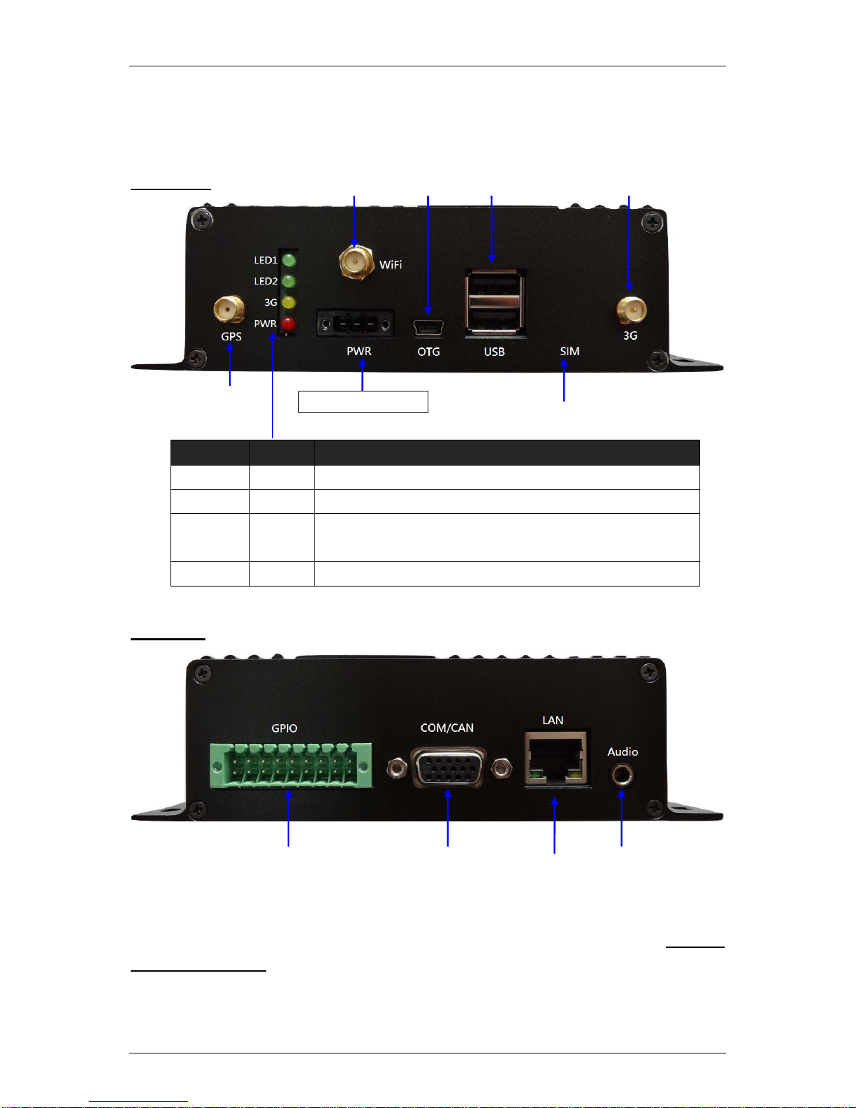
2.2 VPC100 Connectors...............................................................................8
3VPC100 INSTALLATION ..........................................................................9
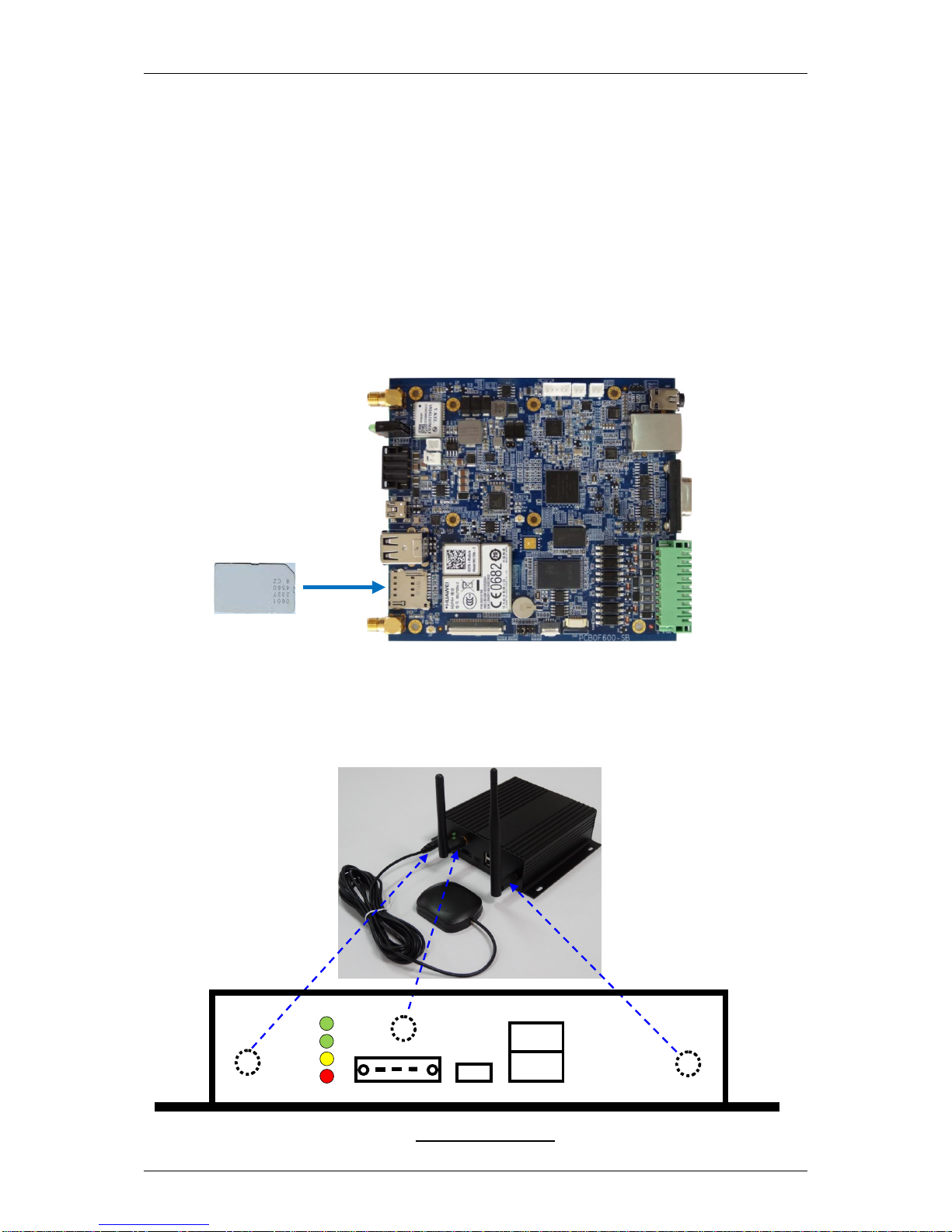
3.1 Basic Installation..................................................................................10
3.2 Full Installation.....................................................................................13
APPENDIX A: VPC 100 DEVICE MANAGER...............................................14
A-1 GPS function........................................................................................15
A-2 GPIO function ......................................................................................16
A-3 3-Axis G-sensor Data ...........................................................................17
A-4 E-compass function..............................................................................18
A-5 System Date & Time.............................................................................19
A-6 System Monitor....................................................................................20
A-7 System Parameter setup.......................................................................21
A-8 Setting Password .................................................................................22
A-9 Setting Network..................................................................................23
A-10 Setting WiFi......................................................................................24
A-11 wcdma monitor.................................................................................25
APPENDIX B: OPENGTS INSTALLATION (WINDOWS) ...............................26
B-1 Hardware Requirements.......................................................................26
B-2 Software Requirements ........................................................................26
B-3 Steps to Install OpenGTS .....................................................................26
APPENDIX C: OPENGTS INSTALLATION (LINUX)......................................32
C-1 Host Computer.....................................................................................32
C-2 OpenGTS Installation procedures..........................................................32
C-3 Change OpenGTS map provider to Google Map ....................................35

VPC100 Quick Start Guide
Page 4
1 Precautions
1.1 Safety Precautions
In order to use this product safely, please take special note of the following
precautions.
•Read all product manuals and related documentation before using this product.
Use this product correctly and safely. Follow all warnings.
•If operating or extending this product in a manner not described in this manual,
please do so at your own risk. Be sure to fully read this manual and other
technical information on our website and proceed safely and responsibly.
•Do not install this product in a place with a lot of water, moisture, dust or soot.
This could cause product failure, fire, or an electric shock.
•Some parts of this product generate heat and can reach high temperatures.
This may cause burns if it is improperly handled. Do not touch the electronic
components or surrounding area while powered on or immediately after being
turned off.
•Carry out any design and development only after you have thoroughly read
and understood this manual and any other related technical materials on the
website or in the data sheets. Test your product thoroughly for reliability and
safety.
•This product is not intended for applications that require extremely high
reliability, safety, functionality and accuracy: including but not limited to medical
equipment, traffic control systems, combustion control systems, and safety
equipment. This company is not liable for death or injury if used in such
systems.
•This product uses semiconductor components designed for generic electronics
equipment such as office automation, communications, measurement
equipment and machine tools. Foreign noise or a power surge may cause this
product to malfunction or fail.
•To ensure there is no risk of bodily harm or property damage, be sure to take
all electrical safety precautions such as protection circuits, limit switches, fuse
breakers, or redundant systems. Only use the device after sufficient reliability
and safety measures are in place.

VPC100 Quick Start Guide
Page 5
1.2 Write Prohibited Regions
1.3 Warranty
As described in the Product Warranty Policy provided with this product, the main
board is covered by a one year replacement warranty starting from the time of
purchase. Please note that the other included goods and software are not covered
under this warranty. Some knowledge used by IC-NEXUS is provided by third parties,
and IC-NEXUS makes no representation or warranty as to the accuracy of such
information.
Data stored by the EEPROM, i.MX6 electrical fuse (e-Fuse) is used by the software
contained in this product. Do not write to these regions as this may cause the product
stop working correctly. Purposely writing to these regions voids the product warranty.

VPC100 Quick Start Guide
Page 6
2 Overview
The VPC100 is a communication gateway designed for in-vehicle applications or IOT
(Internet of Things) applications. The VPC100 offers some unique features, including
the latest NXP iMX6UL (ARM Cortex-A7) application processor, a dual (or quad) band
3G modem and a ublox GPS receiver.
With the latest Linux kernel and tools, the VPC100 allows users to design and deploy
custom software for various applications, such as vehicle tracking, fleet management
and IOT communication gateway.
Features
ARM processor / Linux enables quick software development and deployment
9-36V wide input voltage range for vehicle application
Photo-coupled GPIO for vehicle sensor monitoring
(optional) Bluetooth interface to support BT-based (optional) OBD2 module
Hardware Specifications
NXP iMX6ULARM Cortex™-A7 core @ 500MHz
256MB DDR3 ; 512MB Flash
9V-36V DC power input
(optional) DC power input with over-voltage protection
USB 2.0 host port x2 ; USB 2.0 OTG port x1; Micro SD card socket x1
GPS receiver x1; G-sensor x1; E-compass x1
3G (WCDMA) x1; SIM card socket x1
RS485 port x1; RS232 port x1; CAN bus x1; I2C port x1
Photo coupler GP Input x10; Photo coupler GP Output x2; Analog input x2
10/100 Mbps Ethernet (RJ-45) x1
Audio (MIC and Headphone) (optional)
802.11b/g/n Wifi and Bluetooth 4.0 (optional)
Dimension: 125mm x 147mm x 41mm (L/W/H)
Software Specifications
Yocto 1.8 (Linux kernel 3.14)

VPC100 Quick Start Guide
Page 7
2.1 VPC100 Package Contents
Standard package content:
Item
Notes
VPC100 ---
CD Software and User's Manual
Optional items:
Item
Notes
+12V Power adapter
---
WiFi/Bluetooth Module with Antenna ---
GPS Antenna ---
3G Antenna ---
C220 debug board/cables For VPC100 console, debug port

VPC100 Quick Start Guide
Page 8
2.2 VPC100 Connectors
Front View
Rear View
For detailed descriptions of the VPC100 connector functions, please refer to “VPC100
Reference Manual”.
Label Color Status
LED1 Green Can be set on/off by GPIO2_18
LED2 Green Can be set on/off by GPIO2_19
3G Yellow When VPC100 is connected to 3G network, the LED is ON.
In searching 3G network, the LED keeps blinking.
PWR Red The LED is ON when VPC100 is powered on.
GPS
Antenna
WiFi
Antenna
(optional)
3G
Antenna
USB
Host
USB
OTG
SIM socket
(unscrew front cover to
insert sim card)
GPIO | GND | DC-IN
GPI
GPO
Analog-in
RS232
RS485
CAN
I
2
C
10/100
Ethernet
MIC &
Headphone
(optional)

VPC100 Quick Start Guide
Page 9
3 VPC100 Installation
VPC100 installation is divided into two portions, basic installation and full installation.
You are allowed to perform the following functions after completing basic installation:
(1). A PC (or a mobile phone, a tablet with WiFi function) is connected to internet
through VPC100, and
(2). A PC (or a mobile phone, a tablet with WiFi function) may communicate VPC100
device manager using browser for enquiring various VPC I/O settings, GPS
coordinates, etc. For more information about detailed functions of VPC100 device
manager, please refer to AppendixA in this manual.
You are allowed to perform the following functions after completing full installation:
(1). All functions completed under the basic installation
(2). VPC100 can send information (GPS, I/O, etc.) to remote Server OpenGTS
(3). VPC100 can read vehicle-related data through OBDII Dongle.
For more information about detailed installation, please refer to “Section 3.1 Basic
Installation” and “Section 3.2 Full Installation”.

VPC100 Quick Start Guide
Page 10
3.1 Basic Installation
You need to prepare the following devices and accessories before basic installation:
One VPC100
One 3G SIM Card
One network cable and one PC (Windows), or
One mobile phone/tablet/PC/NB device with WiFi function
Note: You have to additionally purchase WiFi module for VPC100 while
using a WiFi device to connect to VPC100.
Step 1:Inserting 3G sim card into sim card slot on VPC100 (as shown below):
Step 2:Connecting 3G, Wi-Fi, GPS antennas onto antenna connectors on VPC100
(shown as dashed circles in the figure below). Note: WiFi module, 3G antenna, GPS
antenna and WiFi antenna have to be purchased separately.
VPC100 Front Panel
PWR
USB
3G
OTG
SIM
GPS
WiFi
LED1
LED2
3G
PWR

VPC100 Quick Start Guide
Page 11
If you want to:
Connect VPC100 to PC with a network cable, go to Step 3。
Connect VPC100 to a mobile phone or tablet with WiFi function, go to Step 4。
Step 3:Connecting one end of a network cable to VPC100 LAN port and connecting
the other end to PC LAN port. Connect power line to PWR connector on VPC100.
Note: PC is a DHCP client, and fixed IP setting is not allowed. In PC browser, type
http://192.168.1.1 to connect to VPC100 device manager。
Network settings on VPC100:
Default LAN IP address is 192.168.1.1
Username: admin & Password: 12345678.
VPC100 is a DHCP server and it will broadcast an IP address to PC (192.168.1.2
~ 192.168.1.100).
Step 4:Setting the following wireless network settings on an available mobile phone
or a tablet with WiFi function:
WiFi AP SSID name for VPC100: F600-AP
WiFi frequency : Channel 4
WPA mode
To activate VPC100 device manager, enter http://192.168.2.1 on mobile or tablet
browser.
Default WiFi IP address is 192.168.2.1
Username: admin & Password: 12345678.
VPC100 is a DHCP server and it will broadcast an IP address to WiFi phone or
tablet (192.168.2.2 ~ 192.168.2.100).
wifi 3G
LAN cable
RJ45
IP: 192.168.1.1
DHCP server
Broadcast IP to PC
IP: 192.168.2.1
DHCP server
Broadcast IP to phone
Internet
3G
Internet
DHCP client
DHCP client

VPC100 Quick Start Guide
Page 12
Note:
VPC100 Ethernet default IP: 192.168.1.1
VPC100 Ethernet DHCP server IP range: 192.168.1.2 ~ 192.168.1.100
VPC100 WiFi default IP: 192.168.2.1
VPC100 WiFi DHCP server IP range: 192.168.2.2 ~ 192.168.2.100
While connecting to VPC100 device manager, you can either type http://192.168.1.1
or http://192.168.2.1. VPC100 has two IP addresses (for Ethernet and WiFi, 2
network devices). Two network segments 192.168.1.x and 192.168.2.x are bridged
together in VPC100.
Step 5:If you complete above Step1~Step4 you have completed basic installation on
VPC100.After entering VPC100 device manager on PC (or a phone or a tablet with
WiFi function), you may connect to Internet through 3G modem.
For more information about detailed VPC100 device manager functions, refer to
AppendixA.

VPC100 Quick Start Guide
Page 13
3.2 Full Installation
You need to prepare the following devices and accessories before full installation:
One VPC100
One 3G SIM Card
One network cable and one PC (Windows), or
One mobile phone/tablet/PC/NB device with WiFi function
Note: You have to additionally purchase WiFi module for VPC100 while
using a WiFi device to connect to VPC100.
One PC (Windows), which can be installed OpenGTS server software
Before starting full installation, make sure you have successfully completed the basic
installation steps described in previous section.
If it is not properly installed, please complete basic installation first.
OpenGTS server Installtion
Please refer to Appendix B or Appendix C for detailed OpenGTS server installation.

VPC100 Quick Start Guide
Page 14
Appendix A:VPC 100 Device Manager
The default IP address for VPC100 is 192.168.1.1
In your browser’s address bar, enter http://192.168.1.1.
Enter username & password (default username: admin, password: 12345678), and
press Login to log into the system.
NOTE: The source code of VPC100 Device Manager is available for your
modification after a purchase. For more information, please contact our sales
representative.

VPC100 Quick Start Guide
Page 15
A-1 GPS function
When GPS antenna is connected and with signal quality, VPC100 device manager
will display GPS coordinates at 1Hz frequency (refresh coordinates 1 time per
second).
Note: The map used in device manager is Google Map. The PC (or mobile phone)
must be connected to Internet for browser to show GPS coordinates with Google
Map.

VPC100 Quick Start Guide
Page 16
A-2 GPIO function
GPIO OUT can set HIGH/LOW value and output it to GPO pin on VPC100.
For example, to enable (turn on) LED 1, select HIGH on device manager and press
<Change it> to modify its setting. To disable (turn off) LED 1, select LOW on device
manager and press <Change it> to modify its setting.
GPIO IN on device manager can display VPC100 GPIO input values.

VPC100 Quick Start Guide
Page 17
A-3 3-Axis G-sensor Data
This function of 3-axis micro accelerator can measure the changes of x, y, z axes
based on the gravity.
In case the GPS signal quality is poor and this signal loses GPS navigation ability, the
3-axis information combined with E-compass can be used to establish a
complementary azimuth computing system.

VPC100 Quick Start Guide
Page 18
A-4 E-compass function
This page displays VPC100 on-board E-compass 3-axis (x, y, z) data. E-compass
reports the data by measuring the direction of the Earth's magnetic field.
This function can be used to show your present vehicle direction.

VPC100 Quick Start Guide
Page 19
A-5 System Date & Time
This function allows user to set system date and time. In lower portion of user
interface, you may use New Date & Time to set system date and time, and click
<Change it> to change the present time to new system date and time.

VPC100 Quick Start Guide
Page 20
A-6 System Monitor
This System Monitor function can display current usage of CPU & memory on
VPC100.
CPU frequency: For showing present processor operating frequency
CPU usage: For showing present processor usage (loading)
Memory Size
-Total: For showing total system memory capacity
-Free: For showing free system memory capacity
CPU Temperature: For showing present processor temperature
If you need to reboot system, please click <Reboot System > (when you set/update
new system parameters or password, use this button to reboot system).
Table of contents
Other IC nexus Gateway manuals