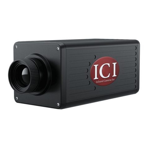
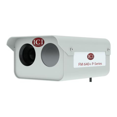
ICI FMX 400 P Series User manual

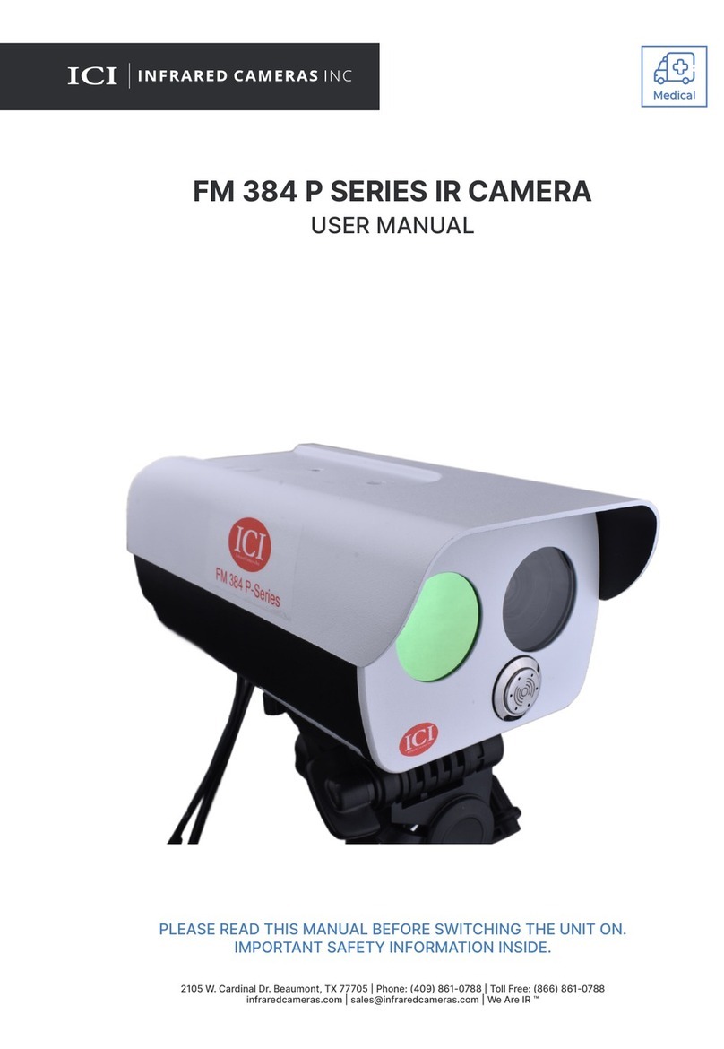
FMX 400 P SERIES IR CAMERA
USER MANUAL
MedicalMedical
Edit Text Outlines
2105 W. Cardinal Dr. Beaumont, TX 77705
PLEASE READ THIS MANUAL BEFORE SWITCHING THE UNIT ON.
IMPORTANT SAFETY INFORMATION INSIDE.
ICI cameras fall under US Federal Law and Export Control.
THIS DEVICE IS INTENDED FOR ADJUNCTIVE USE.
NOT MEANT FOR STANDALONE DIAGNOSTICS.

FMX 400 P SERIES IR CAMERA USER MANUAL
2
©Copyright 2021, Infrared Cameras, Inc. - All rights reserved. The contents
of this document may not be reproduced in whole or in parts without the
written consent of the copyright owner.
Printed in the United States of America.
2105 W. Cardinal Dr.
Beaumont, TX 77705
(866) 861-0788
www.infraredcameras.com
THE MANUFACTURER RESERVES THE RIGHT TO ALTER THE SPECIFICATIONS
OF THE PRODUCT WITHOUT PRIOR NOTIFICATION. THE MANUFACTURER
ALLOWS HIMSELF THE RIGHT TO MODIFY WITHOUT ANY PRELIMINARY
OPINION THE TECHNICAL SPECIFICATIONS OF THE PRODUCT. THIS
MANUAL MAY CONTAIN TECHNICAL INACCURACIES OR TYPOGRAPHICAL
ERRORS.
NOTICE ALL STATEMENTS, INFORMATION, AND RECOMMENDATIONS
IN THIS MANUAL ARE BELIEVED TO BE ACCURATE BUT ARE PRESENTED
WITHOUT WARRANTY OF ANY KIND. NOTWITHSTANDING ANY OTHER
WARRANTY HEREIN, ALL DOCUMENT FILES AND SOFTWARE ARE PROVIDED
“AS IS” WITH ALL FAULTS. ICI DISCLAIMS ALL WARRANTIES, EXPRESSED OR
IMPLIED, INCLUDING, WITHOUT LIMITATION, THOSE OF MERCHANTABILITY,
FITNESS FOR A PARTICULAR PURPOSE AND NONINFRINGEMENT OR
ARISING FROM A COURSE OF DEALING, USAGE, OR TRADE PRACTICE.
THE SOFTWARE LICENSE AND LIMITED WARRANTY FOR THE
ACCOMPANYING PRODUCT ARE SET FORTH IN THE INFORMATION PACKET
THAT SHIPPED WITH THE PRODUCT AND ARE INCORPORATED HEREIN
BY THIS REFERENCE. IF YOU ARE UNABLE TO LOCATE THE SOFTWARE
LICENSE OR LIMITED WARRANTY, CONTACT YOUR ICI REPRESENTATIVE
FOR A COPY.
IN NO EVENT SHALL ICI BE LIABLE FOR ANY INDIRECT, SPECIAL,
CONSEQUENTIAL, OR INCIDENTAL DAMAGES, INCLUDING, WITHOUT
LIMITATION, LOST PROFITS OR LOSS OR DAMAGE TO DATA ARISING OUT
OF THE USE OR INABILITY TO USE THIS MANUAL, EVEN IF ICI HAS BEEN
ADVISED OF THE POSSIBILITY OF SUCH DAMAGES.
FMX 400 P SERIES IR CAMERA USER MANUAL
3
1. General Description
2. Safety Information
3. Intended Use
4. Technical Specifications
5. Structure
6. Package Contents
7. Installation Instructions
8. Computer Setup
9. Cleaning and Maintenance
10. Site and System Validation Checklist
11. Troubleshooting
12. About ICI
Contents
4
4
4
5
6
7
8
13
14
15
18
20

FMX 400 P SERIES IR CAMERA USER MANUAL
4
1. General Description
2. Safety Information
FMX 400 Series IR cameras are specially designed to take the body temperature of a
person and to report the total number of persons scanned. The system has been widely
applied for inspection services, and is available for adjunctive use in: hospitals, and sub-
acute healthcare settings public areas, i.e. airports.
• This device must be installed by qualified service personnel or system installation
personnel.
• Do take precautions to prevent the lens from being worn, scratched or broken. Avoid
touching the lens to prevent it from being damaged or getting dirty.
• Given that the uncooled thermal infrared image camera uses a very sensitive thermal
sensor, under no circumstances (powered on or off) should the lens be pointed
directly at a strong radiation source (such as sun, direct or reflected laser beam, etc.),
otherwise permanent damage will be caused to the uncooled thermal imager.
• This product is a precise electronic device that must be handled with care during use,
storage, and transportation to prevent dangerous actions such as the device being hit
by external force, or falling from heights.
• During transportation and storage, the ambient temperature must not be lower than
• Prior to start of the device, make sure that the power supply is properly connected. If
the power supply is connected incorrectly, the device may be damaged.
• Do not place any objects on the power cord, and do not place the device where the
power cord can be easily touched.
• If the device operates abnormally, please contact the supplier and do not dismantle
the device on your own.
• Do not drop or throw the device.
• Do not put the product into a fire.
• It is recommended to calibrate the device annually.
3. Intended Use
FMX 400 Series IR cameras are designed for body surface temperature measurement of
infants and adults without contacting the human body.

FMX 400 P SERIES IR CAMERA USER MANUAL
5
4. Technical Specifications
Detector Array UFPA
17
FOV
Measurement Distance Lens dependent
384 x 288
50 Hz NTSC/PAL
14-bit
5% to 95% non-condensing
Accuracy
> 99 %
119 mm x 55 mm x 55 mm (L x W x H +/- .5 mm)
DC 110V 10 - 36, < 3 W
< 370 g
Interface RJ-45 Ethernet
raw data
0.01 to 1.0
IP 54
Built-in shutter
SPECIFICATIONS SUBJECT TO CHANGE WITHOUT NOTICE

FMX 400 P SERIES IR CAMERA USER MANUAL
6
5. Structure
1. Coaxial plug interface
2.
3.
1.
2.
3.

FMX 400 P SERIES IR CAMERA USER MANUAL
7
6. Package Contents
Coaxial Cable
Power AdapterEthernet CableFMX Series IR Camera
Software USB Drive
Temperature Reference AC Power Cord
ENSURE ALL SYSTEM EQUIPMENT AND COMPONENT ITEMS ARE
PRESENT BEFORE BEGINNING INSTALLATION

FMX 400 P SERIES IR CAMERA USER MANUAL
8
7. Installation Instructions
B.
Mount the Temperature Reference to
a tripod using the ¼-20 mount. Plug power cord into Temperature Reference.
A.
SELECT AN APPROPRIATE AREA FREE OF IMMEDIATE AIRFLOW
FROM DOORWAYS AND AIR CONDITIONING/VENTILATION
SYSTEMS. THE SELECTED AREA SHOULD HAVE A STABLE

FMX 400 P SERIES IR CAMERA USER MANUAL
9
MAKE SURE TRIPODS DO NOT BLOCK THE DIRECT PATH OF
NOT BE MOVED OR KNOCKED DOWN.USING A DIVIDING BARRIER
WILL HELP KEEP TRIPODS SEPARATE FROM THE PATH.
D.
Mount the FMX Series IR Camera to a
tripod using the ¼-20 mount.
C.
Plug power cord into a 110/120V
electrical outlet.

FMX 400 P SERIES IR CAMERA USER MANUAL
10
G. H.
Attach coaxial cable to back of
the FMX Series IR Camera.
Right to tighten. Left to loosen.
Plug jack end of power adapter into
barrel end of coaxial cable.
E. F.
Plug Ethernet cable into the Ethernet port
of the FMX Series IR Camera.
Plug the other end of the Ethernet cable
into the Ethernet port of the computer.
ENSURE THE CAMERA LENS AND TEMPERATURE REFERENCE
SOURCE ARE FACING EACH OTHER ON PARALLEL PLANES. MAKE
SURE CAMERA TARGET AREA
BACKGROUND.

FMX 400 P SERIES IR CAMERA USER MANUAL
11
I.
Plug power adapter into a 110/120V
electrical outlet.
J.
Power on Devices.
FMX 400 SERIES IR CAMERA
SETUP GUIDE
2105 W. Cardinal Dr. Beaumont, TX 77705
Phone: (409) 861-0788
Toll Free: (866) 861-0788
infraredcamerasinc.com
sales@infraredcamerasinc.com
We Are IR ™
GRAPHIC FOR ILLUSTRATION PURPOSES ONLY
ALLOW AT LEAST 45 MINUTES FOR THE TEMPERATURE
REFERENCE SOURCE TO WARM UP. THIS WILL PROVIDE THE
MOST ACCURATE SKIN TEMPERATURE MEASUREMENTS.
SOFTWARE ARRIVES INSTALLED ON COMPUTERS AND TABLETS
PURCHASED FROM ICI AS COMPLETE SYSTEMS AND IT WILL
LAUNCH AUTOMATICALLY ON STARTUP. AFTER THE SOFTWARE
LAUNCHES THE USER SHOULD ENSURE THE TARGET ZONE IS
IN VIEW OF THE CAMERA AND THE TEMPERATURE REFERENCE
SOURCE IS POSITIONED OFF CENTER TO KEEP THE PERSON
BEING IMAGED AS CENTERED AS POSSIBLE.

FMX 400 P SERIES IR CAMERA USER MANUAL
12
• The technology should be used to measure only one subject’s
temperature at a time.
• Measurements should not be solely, or primarily, relied upon to
diagnose or exclude a diagnosis of any disease.
• Elevated body temperature should be confirmed with
secondary evaluation methods (e.g., an NCIT or clinical grade
contact thermometer).
• Signage should instruct for the removal of glasses, headwear,
and masks.
• Read the current government guidance regarding the
use of telethermographic systems for skin temperature
measurements. Additional information can be found by
essential performance of screening thermographs for human
electrical equipment - Deployment, implementation and
operational guidelines for identifying febrile humans using a
screening thermograph.
CRITICAL INFORMATION

FMX 400 P SERIES IR CAMERA USER MANUAL
13
8. Computer Setup
The FMX 400 comes configured with static IP address for the infrared camera. The infrared
camera lies at 192.168.1.123. Connecting the computer requires setting the IPv4 settings
of the Ethernet port to a static IP address in the same “Class C.” We suggest applying
192.168.1.110 with a subnet mask of 255.255.255.0. There is no need to set a gateway as
this is a direct connection from the computer to the cameras with no router.
Be sure the static IP address is set by doing the following:
1. Click on Windows icon.
2. Click on Settings.
3. Click on Network and Internet.
4. Click on Ethernet.
5. Click on Change Adapter Settings.
6. Right click on Ethernet and choose properties.
7.
8. The IP address should read 192.168.1.110. If it does not, click in the box and fill in the
correct number.
9. The Subnet Mask should read 255.255.255.0. If it does not, click in the box and fill in
the correct number.
10. Click Ok.

FMX 400 P SERIES IR CAMERA USER MANUAL
14
Do not use corrosive chemicals on the optical glass components. The germanium window
surface is coated with anti-reflection coating. Dust, grease, and fingerprints will produce
harmful substances and lead to a decline in performance, or cause scratches. If dirt is
found, please use the following methods:
1. Use a blown balloon or a soft brush to clean the lens surface to avoid dust particles
scratching the anti-reflection film on lens surface during the wiping process.
2. Use a soft cotton cloth or lens wiping paper and dip in alcohol or lens wiping liquid.
Gently wipe the lens surface from the middle to the edge, paying attention to not
crack the lens, or use too much wiping liquid. If the lens is still not clean, replace the
cloth and repeat operation.
9. Cleaning and Maintenance
• Processor: i5 or above (Quad Core or better)
• 4 GB or above
• OS: Windows 8/8.1/10
• 256 GB or above
• 1920 x 1080
Software arrives installed on computers and tablets purchased from ICI as complete
systems and it will launch automatically on startup. A copy of the software is provided on
the Software USB Drive. Documentation can be found online on the IR Flash STM web page
under the Downloads section or at this address:
It is recommended to have your device(s) re-calibrated annually. Contact customer service
to schedule maintenance.

FMX 400 P SERIES IR CAMERA USER MANUAL
15
_______________________________ ___________________________
__________________ ______________________________
**All those tasked with the initial setup of the temperature screening equipment must be
present during this training.
***This portion of the validation requires a live video feed with the instructors.
Ensure that this area is free from:
• Any direct or indirect (reflected) sunlight
• Warm or cold conductive airflow
HVAC vents/intakes
• Any radiant energy from electrical sources
• Direct or indirect lighting on individual being screened
Placement is parallel and perpendicular to screening camera
• At a distance of ~12 feet
Consists of a non-IR reflective homogeneous background
• Minimum size is 10’ x 8’
• White to gray flat finish
The Temperature Reference Source is in front of background (direct line of sight to the
screening camera) and is framed within the screening image
10. Site and System Setup Validation Checklist
Continues

FMX 400 P SERIES IR CAMERA USER MANUAL
16
Establish a guided pathway from the entrance to the screening area
Design this pathway so there is an equilibration time
No restrooms on ingress pathway
Signage should instruct for removal of glasses, headwear, and masks
Mark the point of measurement on the floor (“V/X” or a set of footprints)
The distance is unique to each screening system
Ensure the line of sight from the Temperature Reference Source to the camera is never
blocked by an individual entering or leaving the point of measurement
The secondary screening area should be setup near the screening area
Level on tripod or other suitable support
Perpendicular to floor and individual being screened
Continues

FMX 400 P SERIES IR CAMERA USER MANUAL
17
Height of camera
Larger will require a height adjustment to camera
The individual’s face and Temperature Reference Source should be in the frame
Behind the individual being screened yet visible within the frame of the image
Protect the camera from exposure to direct sunlight to avoid damage to the camera
sensor
On tripod or other stable stand, in front of background, and positioned for visibility
within the frame of the image
Warm-up time is 15 minutes
Set up the software according to the instructions
Documentation can be found online on the IR Flash STM web page under the
Downloads section or at this address:
Final validation is dependent upon a signed copy of this checklist from each person
responsible for each site.
Upon completion please sign below:
Signature: _____________________________ Signature: _______________________________
Print Name: ____________________________ Print Name: ______________________________
Date: ________________

FMX 400 P SERIES IR CAMERA USER MANUAL
18
• Close and reopen software
• Reconnect power & Ethernet cables
• Ensure that camera has been powered on for a few minutes
• Verify that static IP address is correct:
Default IPv4 of 192.168.1.110
Default subnet mask of 255.255.255.0
• Restart computer
• Verify that correct software is installed
• Uninstall & reinstall software, running as administrator
• Verify that firewall is not blocking software
• Try newer or different version of IR Flash STM software
• For FMX 400 cameras:
Adjust electronic focus with middle button
Close and reopen software
Try newer or different version of IR Flash STM software
Restart computer
• Close and reopen software
• Check that software settings are correct:
Reference Source
Temperature Reference Source has crosshair over it
In Inspection System software:
Make sure that facial detection is on
Turn on core body compensation
Set automatic compensation to environmental temperature
11. Troubleshooting

FMX 400 P SERIES IR CAMERA USER MANUAL
19
• Remove masks & glasses
• Camera is proper distance from person
• Camera is at proper height
• Temperature Reference Source in view, perpendicular to camera, but not blocked
• Person is looking directly at camera lens, not at an angle
• Camera is in focus
• Reconnect power to camera & Temperature Reference Source
• Temperature Reference Source power switch is on
• Camera and Temperature Reference Source powered on for several minutes
• Ensure temperatures on back of Temperature Reference Source match
• Restart Computer
• Camera is away from direct sunlight or reflective light
• Plain background
• Try newer version of IR Flash STM software

FMX 400 P SERIES IR CAMERA USER MANUAL
20
12. About ICI
Infrared Cameras, Inc.
2105 W. Cardinal Dr.
Beaumont, TX 77705
Website: www.infraredcameras.com
ICI manufactures complete systems and software. We can provide complete engineering,
software, and OEM solutions. Our Fortune 500 clients rely on us for infrared equipment and
thermography training (which we offer through the Infrared Training Institute).
In addition to providing custom germanium, silica, and sapphire optics, we also build
windows for enclosures, as well as custom pan and tilt units. We can even provide
customizable explosion-proof systems.
Our knowledge and experience stems from years of using infrared imaging and
temperature measurement instruments to provide solutions to: managers, engineers,
scientists, inspectors and operators in space, power companies, medical, pulp and paper,
food industry, research and development, and various process industries. You can see
our products and services used in industrial, commercial, and government applications
business since March, 1995.
Thank you for your dedicated and continued support.
Table of contents
Other ICI IP Camera manuals

ICI
ICI FM PLUS P Series User manual

ICI
ICI 8000 Series User manual

ICI
ICI FMX 320 Series User manual

ICI
ICI SOUND DETECTAI User manual

ICI
ICI T-CAM 160 XT P Series User manual

ICI
ICI FM 384 P Series User manual

ICI
ICI GAS DETECTIR Series User manual

ICI
ICI FM 384 P Series User manual

ICI
ICI 9320 Series User manual