Specifications
Electrical rating: •24VAC(18-30VAC)
•4ampmaximumtotalload
•1ampmaximumperterminal
Temperature control range: 45°Fto90°F(7°Cto32°C)Accuracy:±1°F(±0.5°C)
System congurations:2-stageheat,1-stagecool,heatpump,gas,oil,electric
Timing: Anti-shortCycle:4minutes
BacklightOperation:5secondsaftermodechangeorbuttonpress
Terminations:R,C,W1/O/B,Y,W2,E,G
Important Safety Information
WARNING!
:
Always turn off power at the main power supply before installing, cleaning,
or removing thermostat.
•Thisthermostatisfor24VACapplicationsonly;donotuseonvoltagesover30VAC
•Donotshortacrossterminalsofgasvalveorsystemcontroltotestoperation;thiswilldamageyour
thermostatandvoidyourwarranty
•Allwiringmustconformtolocalandnationalelectricalandbuildingcodes
•Donotuseairconditioningwhentheoutdoortemperatureisbelow50degrees;thiscandamage
yourA/Csystemandcausepersonalinjuries
•Usethisthermostatonlyasdescribedinthismanual
ELECTRICAL SHOCK HAZARD
– Turn off power at the main service panel by removing
the fuse or switching the appropriate circuit breaker to the OFF position before
removing the existing thermostat.
1. Turnoffpowertotheheatingandcoolingsystembyremovingthefuseorswitchingthe
appropriatecircuitbreakeroff.
2. Removecoverofoldthermostat.Thisshouldexposethewires.
3. Labeltheexistingwireswiththeenclosedwirelabelsbeforeremovingwires.
4. Afterlabelingwires,removewiresfromwireterminals.
5. Removeexistingthermostatbasefromwall.
6. Refertothefollowingsectionforinstructionsonhowtoinstallthisthermostat.
To Remove Existing Thermostat
Package Contents/Tools Required
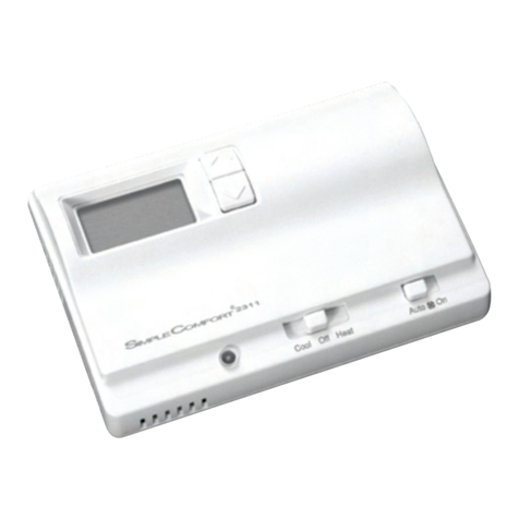
Package includes: SC2311Lthermostatonbase,thermostatcover,wiringlabels,screwsandwall
anchors,Installation,OperationandApplicationGuide
Tools required for installation:Drillwith3/16”bit,hammer,screwdriver
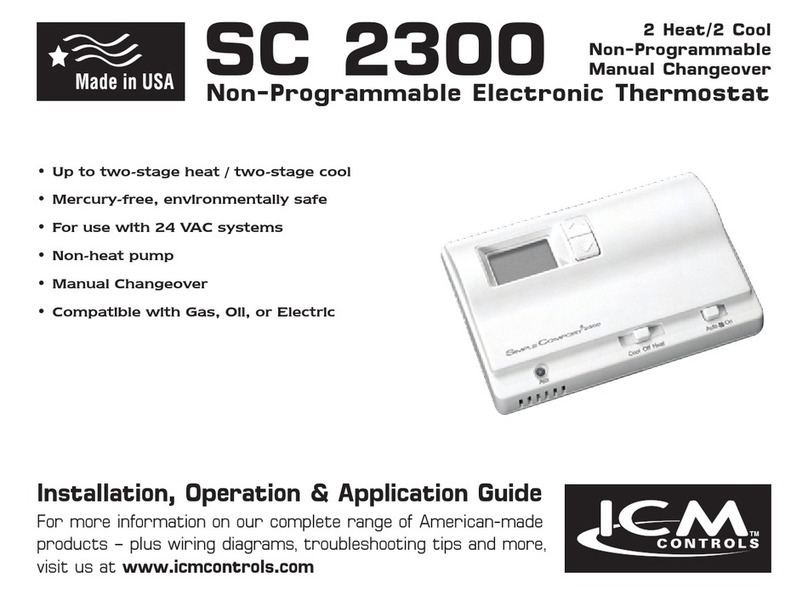
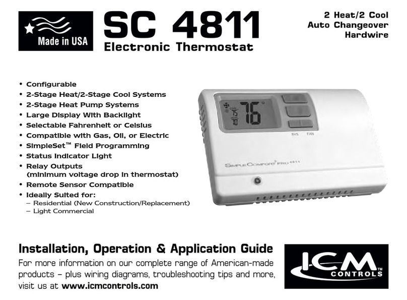
2 Heat/1 Cool
Manual Changeover
Hardwired
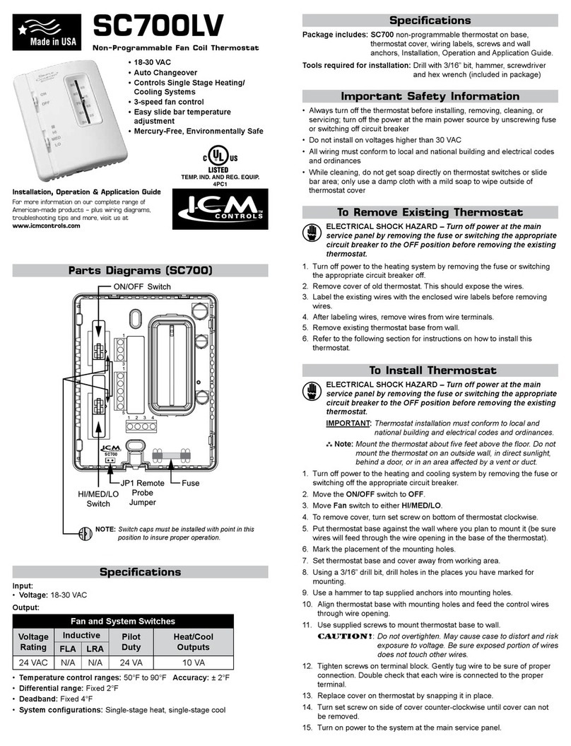
SC2311L
Non-Programmable Electronic Thermostat
Installation, Operation & Application Guide
For more information on our complete range of American-made
products – plus wiring diagrams, troubleshooting tips and more,
visit us at www.icmcontrols.com
• Congurable
• 2-Stage Heat/1-Stage Cool Systems
• Heat Pump Systems
• Backlit Display
• Field Temperature Calibration
• Status Indicator Light
• Relay Outputs
(minimum voltage drop in thermostat)
• Ideally Suited for:
– Residential (New Construction/Replacement)
– Light Commercial
Parts Diagram
Down
button
Up
button
Leftswitch
Resetswitch
RESET
LEFT RIGHT
FP
R
C
W
O/B
Y
W2
E
G
Field
programming
pins
Rightswitch
Modeswitch
Fanswitch StatusLed
ELECTRICAL SHOCK HAZARD
– Turn off power at the main service panel by removing
the fuse or switching the appropriate circuit breaker to the OFF position before
removing the existing thermostat.
IMPORTANT: Thermostatinstallationmustconformtolocalandnationalbuildingand
electricalcodesandordinances.
Note: Mount the thermostat about four feet above the oor. Do not mount the thermostat
on an outside wall, in direct sunlight, behind a door, or in an area affected by a vent
or duct.
1.Turnoffpowertotheheatingandcoolingsystembyremovingthefuseorswitchingtheappropriate
circuitbreakeroff.
2. Toremovecover,insertandtwistacoinorscrewdriverintheslotsontopofthethermostat.
3. Putthermostatbaseagainstthewallwhereyouplantomountit(Besurewireswillfeedthrough
thewireopeninginthebaseofthethermostat).
4. Marktheplacementofthemountingholes.
5. Setthermostatbaseandcoverawayfromworkingarea.
6. Usinga3/16”drillbit,drillholesintheplacesyouhavemarkedformounting.
7. Useahammertotapsuppliedanchorsinmountingholes.
8. Alignthermostatbasewithmountingholesandfeedthecontrolwiresthroughwireopening.
9. Usesuppliedscrewstomountthermostatbasetowall.
10.Insertstripped,labeledwiresinmatchingwireterminals.See“WiringDiagrams”sectionofthis
manual.
CAUTION!
:
Besureexposedportionofwiresdoesnottouchotherwires.
11. Gentlytugwiretobesureofproperconnection.Doublecheckthateachwireisconnectedtothe
properterminal.
12.Replacecoveronthermostatbysnappingitinplace.
13.Turnonpowertothesystematthemainservicepanel.
14.Testthermostatoperationasdescribedin“TestingtheThermostat”.
To Install Thermostat
Terminal Designator Descriptions
R –24VAChot
C –24VACcommon
W1/O/B –Congurable
W1 –1ststageheatfornon-hpsystems
O –coolactivereversingvalve
B – heatactivereversingvalve
Y – 1ststagecool,1ststageheatforheatpumps
W2 –2ndstageheatforheatpump,non-heatpump,andemergencyheat
E – 1ststageheatforEmergencyHeatoperation
G –Fan
SC2311L Output Chart
1ST Cool 1ST Heat 2ND Heat
Heat/Cool Y,G W1,G* W1,W2,G*
Heat Pump (One Compressor) Y,G,O Y,G,B Y,W2,G,B
Emergency Heat HP N/A E,G E,W2,G
* G not energized when congured as a gas/oil system
TheSC2311Lthermostatiscongurablefordifferentsystems.Thecongurationdirectlyeffectsthe
outputs.
Usetheoutputcharttocorrectlycongureandwirethethermostattoyoursystem.
Second
HeatingControl
First
HeatingControl
Fan
Control
Electric Heat
Single Transformer
Second
HeatingControl
First
HeatingControl
Gas/Oil Heat
Single Transformer
Wiring Diagrams
CoolingControl
Fan
Control
Second
HeatingControl
First
HeatingControl
Fan
Control
CoolingControl
Single TransformerSingle Transformer
Single Compressor
2ndStage
Heat
Reversing
Valve
Compressor
Emergency
Heat
Fan
Control
1. Temperature Scale (F or C)–ChooseFahrenheitorCelsius.
Presstheupordownbuttontoselect.
Pressthe RIGHT buttontoadvancetothenextscreen.
2. 1st Stage Temperature Differential(1°Fto5°F)(0.5°Cto2.5°C)
Setthenumberofdegreesbetweenyour“setpoint”temperatureandyour“turn
on”temperature.
Pressthe upordownbuttontosetdifferentialvalue.
PresstheRIGHTbuttontoadvancetothenextscreen.
Configuration Mode Settings
ThecongurationmodeisusedtosettheSC2311Ltomatchyourheating/coolingsystem.The
SC2311Lfunctionswithheatpump,airconditioning,gas,oilorelectricheatsystems.
ToconguretheSC2311L,performthefollowingsteps:
1. Removethecoverofthethermostatbygentlypullingononeofthetopcorners.
2. SimultaneouslyholdtheLEFTandRIGHTbuttonsinfor5secondswhiletheSC2311LisinOFF
mode.
3. Presstheupordownbuttontochangesettingswithineachscreen.
4. PresstheRIGHTbuttontoadvancetothenextscreen.
Note: The LEFT button will return you to the previous screen.
5. Toexitcongurationmode,slidetheModeswitchtoHeatorCool.
3. 2nd Stage Temperature Differential(1°Fto5°F)(0.5°Cto2.5°C)
Setthenumberofdegreesbetweenwhenstage1turnsonandwhenstage2
turnson.
Presstheupordownbuttontosetdifferentialvalue.
PresstheRIGHTbuttontoadvancetothenextscreen.
5. Heat Source (o,b,g,E)
Changebetween“o”Heatpumpcoolactive,“b”Heatpumpheatactive,“g”
(Gas)and“E”(Electric).
Presstheupordownbuttontosetheatsource.
PresstheRIGHTbuttontoadvancetothenextscreen.
4. Staged Off Outputs
Selectwhethertheoutputsforheatingandcoolingarestagedoff
independentlyoraresatisedsimultaneously.
1=outputsstagedoffindependently
0=outputsoffsimultaneously
Presstheupordown buttontoset.
Pressthe RIGHT buttontoadvancetothenextscreen.
6. Auxiliary Delay ON–(0-30minutes)–Setthedelaytimeinminutesforauxiliary
heattobelockedoutafteracallforsecondstage.Thisextrasavingsfeatureis
usedtotemporarilylockoutauxiliaryheatdevices,allowingjustheatpumptotry
tosatisfyheatcall.
Presstheupordownbuttontoselect.
PresstheRIGHT buttontoadvancetothenextscreen
7. Lockout (0°F-8°F)(0°C-4°C) –Selectthenumberofdegreessettemperature
canbechangedduringkeypadlockout
Pressthe upordownbuttontoselect.
Pressthe RIGHTbuttontoadvancetothenextscreen.
8. Maximum Heat Setpoint(45°Fto90°F)(7°Cto32°C)
AdjusttocontrolthemaximumHeatsettemperatureallowed.
Presstheupordownbuttontoselect.
Pressthe RIGHTbuttontoadvancetothenextscreen.
9. Minimum Cool Setpoint(45°Fto90°F)(7°Cto32.0°C)
AdjusttocontroltheminimumCoolsettemperatureallowed.
Presstheupordownbuttontoselect.
Pressthe RIGHTbuttontoadvancetothenextscreen.
10.Room temperature offset(+9°Fto-9°F)(+4.5°Cto-4.5°C)
Adjusttocalibratedisplayedroomtemperaturetomatchactualroom
temperature.
Note: When not set to 0, ROOM will display.
Presstheupordownbuttontoselect.
Pressthe RIGHTbuttontoadvancetothenextscreen.
11. Maximum compressor cycles allowed per hour(-,2-6)
-=asmanyasneeded,and2-6=maximumcycles/hour
Presstheupordownbuttontoselect.
PresstheRIGHTbuttontoadvancetothenextscreen.
12.Cooling Fan Delay Off Time(0,30,60,90seconds)
Selectthefanpurgetimeforcooling.
Presstheupordownbuttontoselect.
Pressthe RIGHT buttontoadvancetothenextscreen.
13.Status Indicator Light(Lt0,1,2)
0=Statusindicatorneveron
1=Statusindicatoronwithrststage
2=Statusindicatoronwithsecondstage
Presstheupordownbuttontoselect.
Note: Red light indicates heating cycle and green light indicates cooling cycle.
SlidetheModeswitchtoHeatorCooltoexitconguration.


