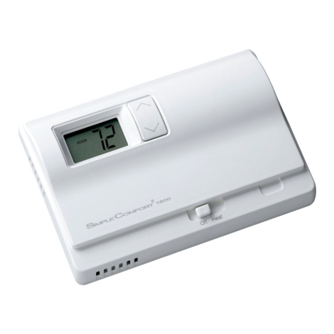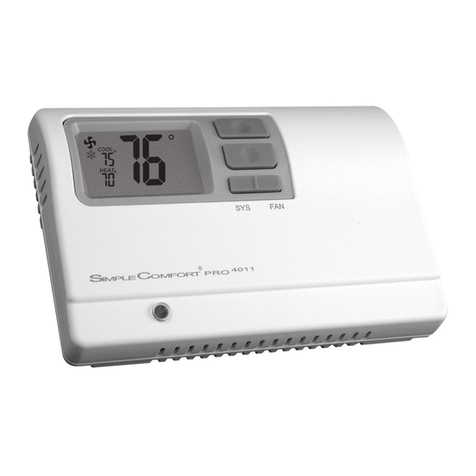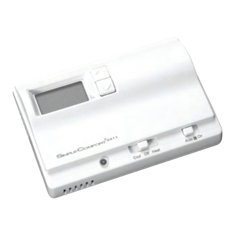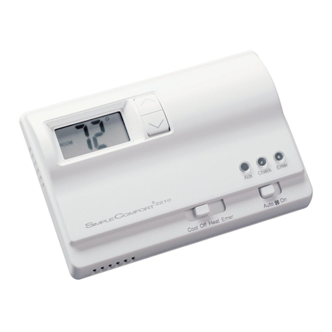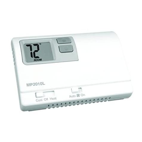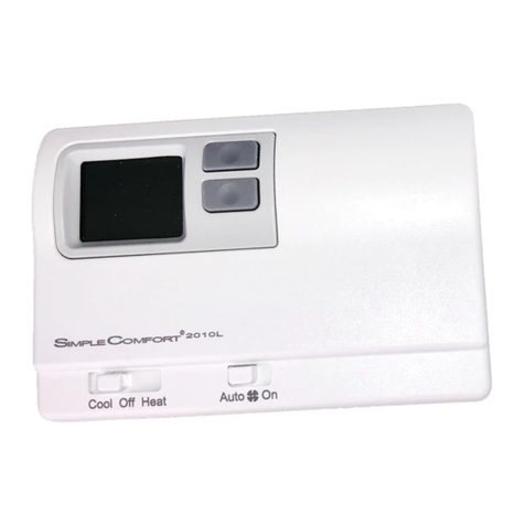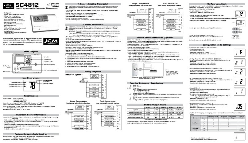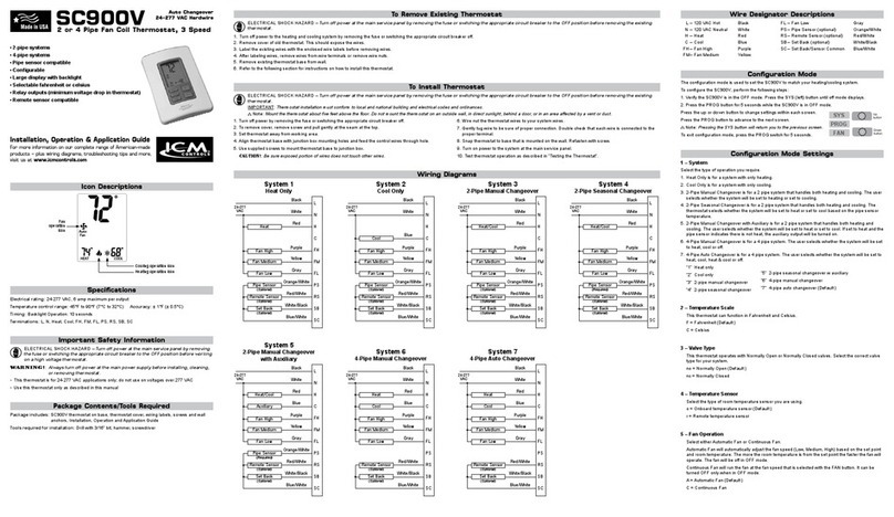
Parts Diagram
Mode Switch Fan Switch
Celsius/
Fahrenheit
Jumper
Reset Button
Heat Pump/
Non-Heat
Pump Jumper
Gas/Electric
Switch
F–C
NON–HP
HP
Cool Heat
Off
OnAuto
Electric
Gas
Manual Changeover
Non-Programmable
Hardwired
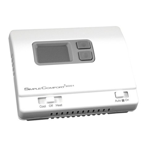
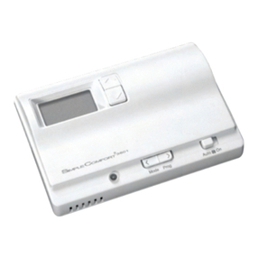
SC2001
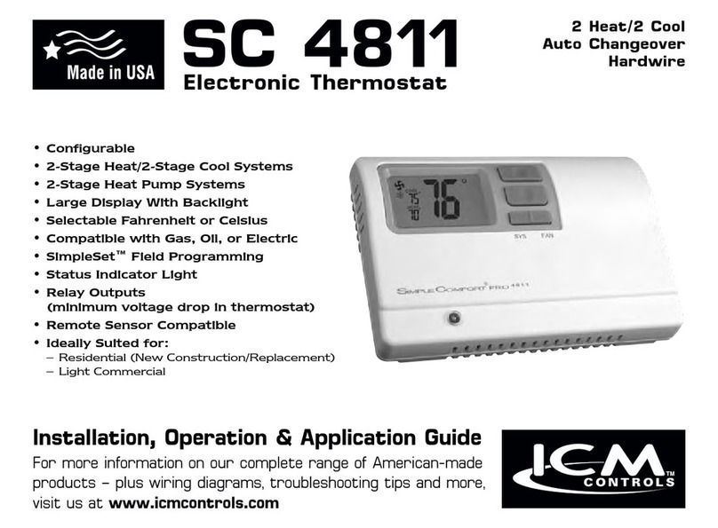
Non-Programmable Electronic Thermostat
General Description
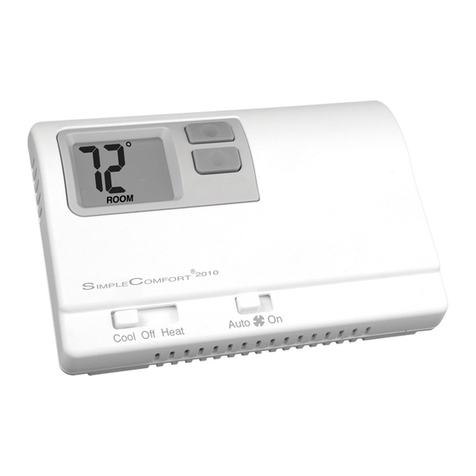
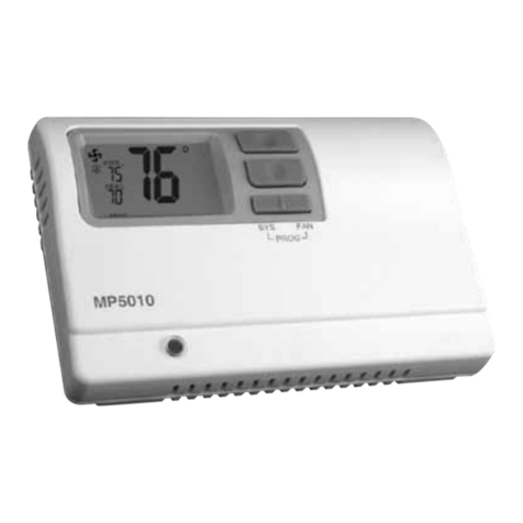
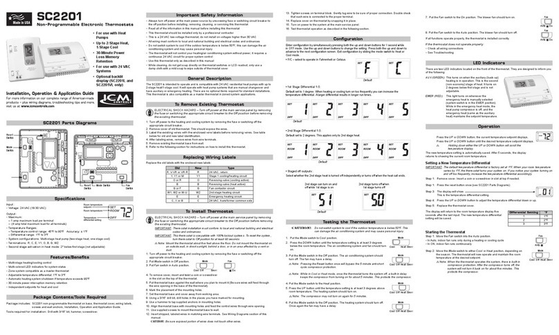
•The SimpleComfort®2001 thermostat is a hardwired, digital, mercury-free, non-programmable,
electronic thermostat
• Compatiblewithsinglestageheating systems, heating/cooling systems, and heat pump
systems, works with gas, oil, or electric systems
• Suitableasamaster thermostat in zoned system applications
• Separatesetpointsforheatingandcooling
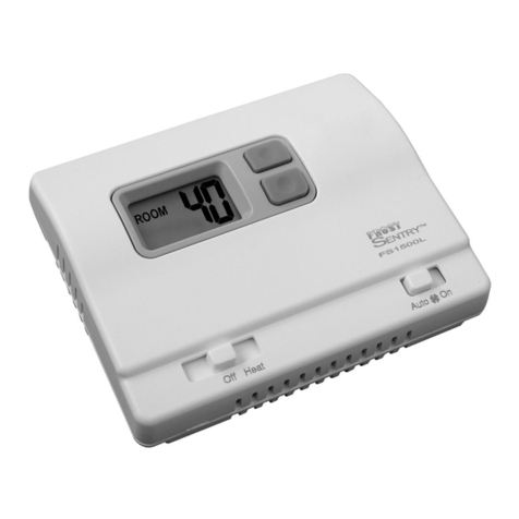
• Freeze Protection Feature:Protectspipesfromfreezing!Iftheroomtemperaturedropsto40°F,
thethermostatautomaticallyturnsontheheat;thethermostatmustbeintheHeatposition
• Built-in Compressor Protection for Air Conditioners; to protect the A/C’s compressor, there is a
5-minutedelaybetweenthesystemturningoffandtheA/Cstarting
• 30-minutepowerlossmemoryretentionprotection
Package Contents/Tools Required
Package includes: SimpleComfort®2001non-programmablethermostatonbase,thermostatcover,
wiringlabels,screwsandwallanchors,Installation,OperationandApplication
Guide.
Tools required for installation:Drillwith3/16”bit,hammer,screwdriver.
Important Safety Information
• Alwaysturnoffthethermostatbeforeinstalling,removing,cleaning,orservicing;turnoffthepower
atthemainpowersourcebyunscrewingfuseorswitchingoffcircuitbreaker
• Donotswitchto“Cool”ifoutsidetemperatureisbelow50°F (10°C),thiscoulddamageyourA/C
system and cause injury
• Donotinstallonvoltageshigherthan30VAC
• Allwiringmustconformtolocalandnationalbuildingandelectricalcodesandordinances
• Whilecleaning,donotgetsoapdirectlyonthermostatswitchesorLCDreadout;onlyuseadamp
clothwithamildsoaptowipetheoutsideofthethermostatcover
Specifications
Input:
•Voltage:18-30VAC
Output:
•Maximum:1ampperterminal(3amptotalforallterminals)
Temperature Ranges:
•Temperature control range: 45°Fto90°F(7°Cto32°C)
Accuracy: ± 1°F (± 0.5°C)
•Differential range: 1°Fto3°F(0.5°Cto1.5°C)
Accuracy: ± 1°F (± 0.5°C)
•System congurations:Single-stageheatpump
•Terminations:R,C,W,Y,B,OG
Note: This thermostat is designed for: Single stage gas, oil, or electric heating, heating/
cooling systems and heat pump systems. It will retain your setpoint temperatures in
memory for up to 30 minutes during a power outage.
SET
ROOM
DIFF
Room
temperature
setpoint
Room
temperature
Temperature
differentialsetting
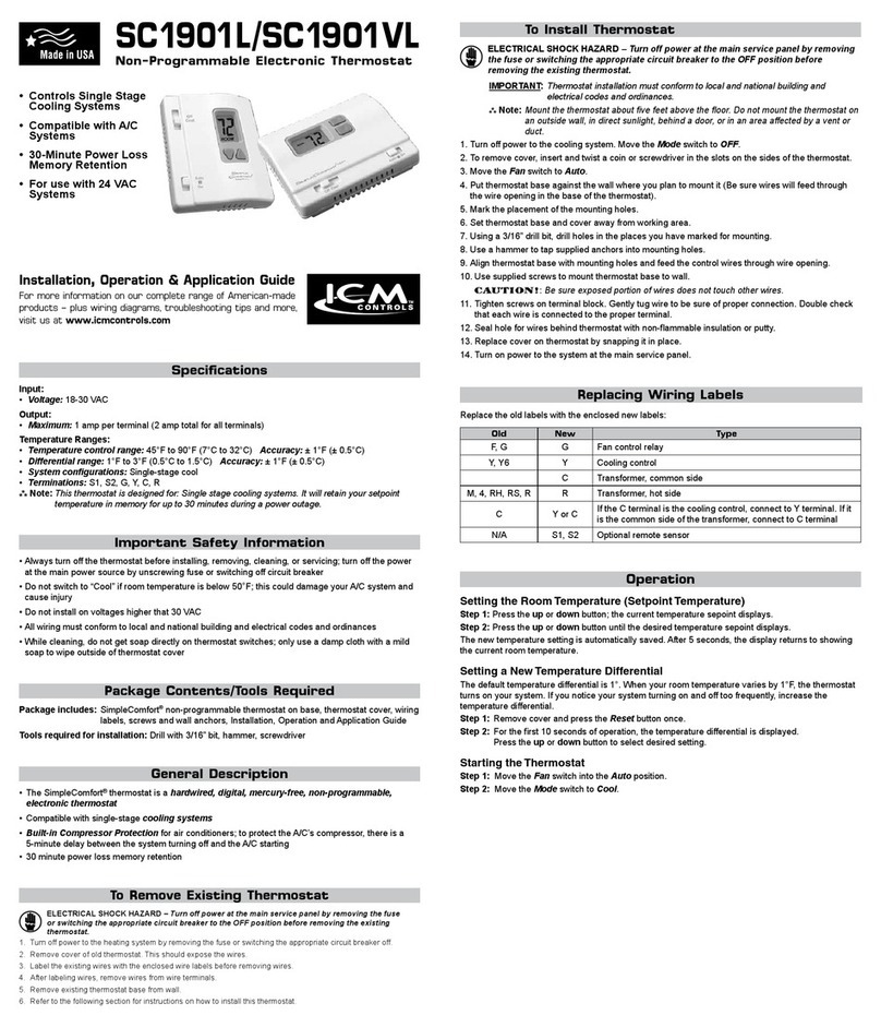
To Install Thermostat
ELECTRICAL SHOCK HAZARD
– Turn off power at the main service panel by removing
the fuse or switching the appropriate circuit breaker to the OFF position before
removing the existing thermostat.
IMPORTANT: Thermostatinstallationmustconformtolocalandnationalbuildingand
electrical codes and ordinances.
Note:
Mountthethermostataboutvefeetabovetheoor.Donotmountthethermostaton
anoutsidewall,indirectsunlight,behindadoor,orinanareaaffectedbyaventor
duct.
1. Turn off power to your system.MovetheMode switch to Off
.
2. MovetheFan switch to Auto.
3. Toremovecover,insertandtwistacoinorscrewdriverintheslotsonthesidesofthethermostat.
4. Putthermostatbaseagainstthewallwhereyouplantomountit(Besurewireswillfeedthrough
thewireopeninginthebaseofthethermostat).
5. Marktheplacementofthemountingholes.
6. Setthermostatbaseandcoverawayfromworkingarea.
7. Usinga3/16”drillbit,drillholesintheplacesyouhavemarkedformounting.
8. Useahammertotapsuppliedanchorsintomountingholes.
9. Alignthermostatbasewithmountingholesandfeedthecontrolwiresthroughwireopening.
10.Usesuppliedscrewstomountthermostatbasetowall.
CAUTION!
:
Be sure exposed portion of wires does not touch other wires.
11.Tightenscrewsonterminalblock.Gentlytugwiretobesureofproperconnection.Doublecheck
that each wire is connected to the proper terminal.
12.Sealholeforwiresbehindthermostatwithnon-ammableinsulationorputty.
13.SettheGas/Electric switch to electric or gas/oil, and heat pump jumper to NON-HP or HP.
14.SetthetemperaturescalejumpertoFahrenheitorCelsius.
15.Replacecoveronthermostatbysnappingitinplace.
16.Turnonpowertothesystematthemainservicepanel.
Operation
Setting the Room Temperature (Setpoint Temperature)
Step 1: Press the or button;thecurrenttemperaturesepointdisplays.
Step 2: Press the or buttonuntilthedesiredtemperaturesepointdisplays.
Thenewtemperaturesettingisautomaticallysaved.After5seconds,thedisplayreturnstoshowing
the current room temperature.
Setting a New Temperature Differential
Thedefaulttemperaturedifferentialis1°.Whenyourroomtemperaturevariesby1°F,thethermostat
turnsonyoursystem.Ifyounoticeyoursystemturningonandofftoofrequently,increasethe
temperature differential.
Step 1: RemovecoverandpresstheResetbuttononce.
Step 2: Fortherst10secondsofoperation,thetemperaturedifferentialisdisplayed.
Press the or buttontoselectdesiredsetting.
Changing Fahrenheit to Celsius
ThetemperaturedisplaysindegreesFahrenheitasafactorysetdefault.Followthesestepsto
changetodegreesCelsius:
Step 1: Removethecover.
Step 2: MovetheF/C jumper to the desired position, For Cusingthecenterpinasacommon.
Step 3: Press the Reset buttononceandreinstallthecover.
YourLCDreadoutchangesaccordingly.
Starting the Thermostat
Step 1: MovetheFan Auto/On switch into the Auto position.
Step 2: MovetheMode switch to Heat or Cool,dependingontheseason
• ControlsSingleStageHeating/Cooling
Systems
• SingleStageHeatPumpSystems
• CompatiblewithGas,OilorElectric
Systems
• 30-MinutePowerLossMemory
Retention
• Forusewith24VACSystems
Replacing Wiring Labels
Old New Type
F, G G Fan control relay
O O Coolactivereversingvalve
B B Heatactivereversingvalve
Y,Y6 Y Coolingcontrol
H,W,4 W Heatingcontrol
C Transformer, common side
M,4,RH,RS,R R Transformer, hot side
CYorC IftheCterminalisthecoolingcontrol,connecttoYterminal;ifitis
the common side of the transformer, connect to C terminal
Replacetheoldlabelswiththeenclosednewlabels:
To Remove Existing Thermostat
ELECTRICAL SHOCK HAZARD
–
Turn off power at the main service panel by removing
the fuse or switching the appropriate circuit breaker to the OFF position before
removing the existing thermostat.
1. Turnoffpowertotheheatingandcoolingsystembyremovingthefuseorswitchingoffthe
appropriatecircuitbreaker.
2. Removecoverofoldthermostat.Thisshouldexposethewires.
3. Label the existing wires with the enclosed wire labels before removing wires.SeeReplacing
WiringLabelstable(below)onothersideforoldandnewlabelidentication.
4. Afterlabelingwires,removewiresfromwireterminals.
5. Removeexistingthermostatbasefromwall.
6. Refertothefollowingsectionforinstructionsonhowtoinstallthisthermostat.
