ICMA S001 Manual

ICMA s.p.a. via Garavaglia, 4 20012 Cuggiono (MI) – ITALY - Tel. +39 02 97249134 / +39 02 97249135 Fax +39 02 97241550
www.icmaspa.it e-mail: [email protected] pag. 1
FUNCTION
Series S001 and S002 circulation units
are applied to the primary circuit of
solar systems and oversee management
of the solar panel - storage tank fluid
thermodynamic cycle for subsequent
supply to utilities via hydraulic
distribution circuits.
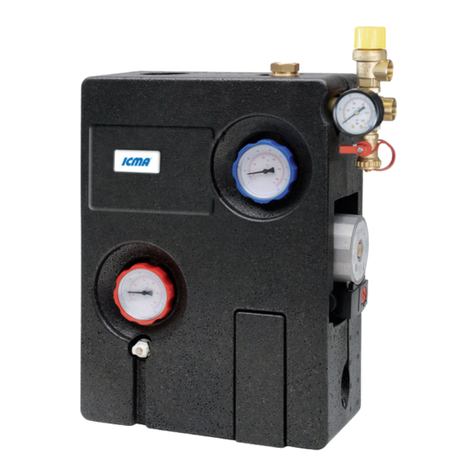
They consist essentially of a circulator
with appropriate performance (rate of
flow/head) and regulation and control
devices governing the operating circuit.
Technical Information Sheet 07/2013 - ENG
TECHNICAL FEATURES
Fluid used: Water, glycol solutions
(glycol 25%÷50% max)
Permitted temperature range: -10 °C / +160°C
Max. ambient temperature: +40°C
Max. operative pressure: 10 bar
Min. pressure on intake
opening with temperatures of: +50 °C : 0,05 bar
+95 °C : 0.3 bar
+110 °C : 1 bar
Min. pressure for opening on/off
and check valve: ∆p:2Kpa (200 mm c.a.)
Safety valve
Calibration of safety valve: 6 bar
Safety valve temperature range: -30÷160°C
Connections of safety valves: 1/2" F
Further information
Manometer scale: 0÷6 bar
Thermometer scale: 0÷160 °C
System connections: 3/4” M
Connection with expansion tank: 3/4” M
Filling/emptying connections
with hose connection: Ø 13 mm
Component materials
Body Brass EN 12165 CW617N
Thermometer Steel/Alluminium
Seals PTFE
Sealing elements EPDM-Perox
Flat seals Betaflex
Insulation shell PPE, Conducibility λ(∆T):
0.041 (W/mK)
Art.S001-S002 SOLAR MODULE WITH
DELIVERY AND RETURN CONNECTIONS
Pump model: - Wilo “Solar ST20/6”
- Grundfos “Solar 15-65”
Centre-to-centre distance: 130 mm
Electrical power supply: 230V - 50Hz
Operatine temperature: -10°C÷110°C c.a.
Max. temperature: 140°C for max 2 hours
Max. operating pressure: 10 bar
Protection level: IP 44
Art.S001 Art.S002
Pump hydraulic features
Grundfos “Solar 15-65”
Water flow (m
3
/h) (1, 2, 3 = Fast pump)
Pump hydraulic features
Wilo “Solar ST20/6”

ICMA s.p.a. via Garavaglia, 4 20012 Cuggiono (MI) – ITALY - Tel. +39 02 97249134 / +39 02 97249135 Fax +39 02 97241550
www.icmaspa.it e-mail: [email protected] pag. 2
COMPONENTS
1. Safety valve for solar energy systems Art.S120 G1/2”F – G1/2”F
2. Instrument holder connection with manometer 0-6 o 0-10 bar
3. Taps for filling, emptying and washing the system
4. On/off valve with built-in thermometer and return connection with Anti-gravity non return valve
5. Wilo Solar ST20/6 o Grundfos Solar 15-65 circulation pump
6. Flow controller with on/off valve, return connection
7. On/off valve with built-in thermometer and delivery connection
8. Air bleeding device
9. Preformed insulating base
10. Hose connection
11. Preformed insulating cover
12. Inspection compartment insert
13. Molex connector
14. Cable duct groove
DIMENSIONS
Code A B C D E F G H I L Weight
(Kg)
S001 G ¾” M 100 140 325 480 420 260 60 60 170 7.0
S002 G ¾” M / 140 275 480 420 235 40 60 170 5.0
Tab.2
Ar
t.S00
2
Tab.1
Ar
t.S00
2Ar
t.S00
1
Art.S001

ICMA s.p.a. via Garavaglia, 4 20012 Cuggiono (MI) – ITALY - Tel. +39 02 97249134 / +39 02 97249135 Fax +39 02 97241550
www.icmaspa.it e-mail: [email protected] pag. 3
TECHNICAL SPECIFICATIONS
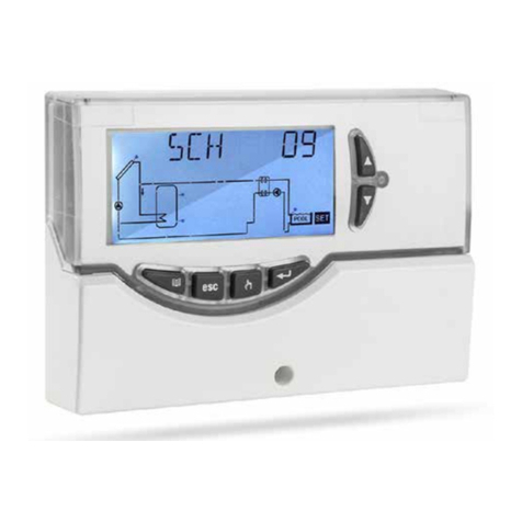
Modules S001 and S002 receive a signal from the external controller (differential temperature controller), which has at least
two temperature sensors (one is positioned on the panel outlet pipe and the other is an immersion sensor in the boiler),
constantly reading the temperature difference and keeping it within the established range, which normally varies between 5 and
8 °C. If the ∆t between the panel and the boiler is found to be over the established set point, the controller starts up the pump
on the module to provide the lacking thermal load. If, on the other hand, the ∆t is narrower than the one set, the internal pump
will be disabled. For further clarification about the electronic controller functioning, please consult the technical
documentation 004/08 about art. S301 and S302.
FILLING THE SYSTEM
1. Open the on/off valve connected with the air bleed valve A (Fig.1), located at the highest point of the system.
2. Open the on/off and check valves, turning the ball valves with the handle with the thermometer on it (4, 7 in Tab.1).
3. Fill the system with a pump, using the tap at the lowest part of the system (3 in Tab.1), until air stops coming out of the
air bleed A (Fig.1).
4. Close the on/off valve on the air bleed valve (7 in Tab.1).
5. Close the tap (3 in Tab.1).
WASHING THE SYSTEM
1. Close the flow control ball valve (6 in Tab.1).
2. Let fluid flow through the solar panels and the heat exchange circuit using an external washing pump linked via a rubber hose to
the safety unit filling/emptying tap (1, 2, 3 in Tab.1), until fluid flows out of the flow controller filling/emptying tap (3 in Tab.1).
3. Briefly open the ball valve in the flow controller (6 in Tab.1) to expel all the air from the system.
4. Leave the external pump running in the system for a few minutes to make sure that it is thoroughly washed, following the
instructions provided with the external washing pump.
Fig.1
A
3
A A
3
3
Fig.1

ICMA s.p.a. via Garavaglia, 4 20012 Cuggiono (MI) – ITALY - Tel. +39 02 97249134 / +39 02 97249135 Fax +39 02 97241550
www.icmaspa.it e-mail: [email protected] pag. 4
START-UP
1. Close the filling/emptying tap on the flow controller (6 in Tab.1) and increase the system’s pressure up to the maximum
permitted value. Close the tap when this value is reached.
2. Open the valve on the on/off assembly (4, 7 in Tab.1) and operate the pump (5 in Tab.1).
3. Leave it to circulate for a certain amount of time, and then check the hydraulic seals in the system.
4. Open the air bleed valves A (Fig.1) again, removing air from the system again by turning on the circulation pump briefly.
5. Restore the desired air pressure.
6. The rate of flow of the system may be modified using the flow controller (6 in Tab.1), working the ball valve above the
graduated scale (refer to flow meter description). In order to do this the pump must be set to maximum power. Follow the
solar panel manufacturer's instructions to adjust or limit the rate of flow.
7. After a few hours of operation, remove air from the solar energy system again at the highest point in the system A (Fig.1)
and in the air separator (8 in Tab.1). When you have finished bleeding air, check the pressure in the system and restore the
desired operating pressure if necessary.
EMPTYING THE SYSTEM
The system must be emptied if it has been filled with water only and will be exposed to a risk of freezing.
1. Open the on/off and check valves by turning the thermometer holder to 45° (4, 7 in Tab.1).
2. Open the air bleed devices at the highest point A (Fig.1).
3. Open the emptying tap at the lowest point in the system (3 in Tab.1).
INSTALLATION AND WALL MOUNTING
The fixing of the delivery part (A) and return part (B) to the insulation shell (C) is made in the factory by two screws M8x35mm
and two washers (D).
The supporting plate (E) and the dowels for the wall fixing (F) are optional.
To install the solar module please proceed as follows:
1. Lay the pipes inside the solar system, leaving enough space for the solar module as shown in Table N.2 (page 2).
2. Define the positioning of the module on the wall and mark the position of the 4 holes for the fixing (F).
3. Drill the wall and insert the dowels (dowels are not included).
4. Fix the solar module to the wall and connect it to the system pipes.
5. Check that all unions are properly tight.
6. Proceed with the electrical wiring.
Fig.2
A
B
Fig.3
C
D
E
G
F

ICMA s.p.a. via Garavaglia, 4 20012 Cuggiono (MI) – ITALY - Tel. +39 02 97249134 / +39 02 97249135 Fax +39 02 97241550
www.icmaspa.it e-mail: [email protected] pag. 5
CONTROLLER
Open position
Vertical
screwdriver cu
t
CONTROLLER
O
p
en
p
osition
Horizontal
screwdriver cu
t
Example of reading: 5 l/min
FLOW METER
The flow meter (6 in Tab.1) is an instrument for measuring the rate of flow of fluid circulating in the system.
The flow meter has a rate of flow limiter which may be adjusted manually with a screwdriver (Fig.4).
A rate of flow indicator present inside the measurement device and a graduated scale on the glass permit real time display of
the rate of flow in the circuit (Fig.5). The scale’s range is 0-12 lt/min.
The only possible position for assembly is vertical (Fig.4).
FLOW RATE READING
Fig.4
Flow controller
(open position)
Drain coo
k
Flow
indicator
GRADUATED RATE OF
FLOW SCALE (L/MIN)
LEVEL
INDICATOR
Fig.5

ICMA s.p.a. via Garavaglia, 4 20012 Cuggiono (MI) – ITALY - Tel. +39 02 97249134 / +39 02 97249135 Fax +39 02 97241550
www.icmaspa.it e-mail: [email protected] pag. 6
CHECK VALVE AND ON/OFF VALVE
The assembly has an on/off valve with thermometers incorporated in the adjustment flywheels (4, 7 in Fig.6).
The valves permit interception of delivery (7 in Tab.1) and return (4 in Tab.1) flow to permit replacement of the pump (while
shut down) even when the system is full. To permit fluid to flow in both directions, it is necessary to turn the flywheels on the
ball valves 45° (Fig.7). During normal operation the valve should be turned to the fully open position (Fig.8).
AIR BLEED DISTRIBUTOR
(air separation device is not included in Art.S002)
Solar module S001 has an air bleed distributor (8 in Tab.1) positioned on the
delivery line. Gases are separated from the head conveying fluid and accumulate in
the upper part of the deaerator.
During start-up, accumulated gases must be evacuated periodically during the day
using the manual air bleed valve, with a screwdriver appropriate to the size of the
bleed valve.
After this, depending on the amount of air in the system, the operation may be
repeated either once a week or once a month.
Lastly, use the deaerator to bleed the system once every 6 months to keep the solar
installation running efficiently.
Danger of burning !
When bleeding the system, if fluid pressure and temperature are high enough, slackening the
screw could produce a jet of superheated liquid or steam.
Proceed as follows to avoid accidents:
- Carefully push and turn the rod inwards using an appropriate screwdriver.
- Protect components and electrical connections from water.
- Start up the pump again.
Fig.8
Reference
notches
Fig.6
Reference
notches
Thermometer holder
(closed position)
Fig.7
45°
Reference
notches
Open
passage
Rotation 45°

ICMA s.p.a. via Garavaglia, 4 20012 Cuggiono (MI) – ITALY - Tel. +39 02 97249134 / +39 02 97249135 Fax +39 02 97241550
www.icmaspa.it e-mail: [email protected] pag. 7
SAFETY
Safety warnings
Read assembly and operating instructions carefully before starting up the system in order to prevent accidents and
damage to the system caused by improper use. Remember that your rights under the warranty will be forfeited if
you make any changes to the system or tamper with it during assembly and construction without authorisation. In
addition, you must follow the requirements of the regulations listed below:
DIN 4751
Water heating systems
DIN 4757
Solar heating systems
DIN 18380
Heating systems and hot water heating systems
DIN 18382
Electrical systems and pipes in buildings
DIN 12975
Thermal solar systems and components
OPERATING CONDITIONS
The limits on operating values specified must not be exceeded under any circumstances. Safe operation is guaranteed if you
comply with the general conditions and limits on operating valves described in this information sheet.
SAFETY STANDARDS FOR ASSEMBLY AND INSPECTION
Assembly and inspection operations must always be performed by qualified, authorised personnel familiar with the
instructions contained herein. Make sure the system is shut down before performing any work on it.
ELECTRICAL CONNECTIONS
Electrical connections must be made by qualified personnel. Connecting cables must be positioned in the cavity provided for
the purpose in the insulating shell (14 in Tab.1) so as to avoid contact with the body of the pump motor and with pipes.
Check that the power supply voltage is as specified on the plate before turning on the pump. All connections must be made as
required by law.
MAINTENANCE
Maintenance work must always be performed by qualified, authorised personnel familiar with the instructions contained
herein. Make sure the system is shut down before performing any work on it. When replacing the pump, turn the on/off valve,
return connection (4 in Tab.1) and flow control valve (6 in Tab.1) to the off position.
Warning! Depending on operating conditions in the pump and the system, the
surface temperature could be very high. Touching the pump directly comports
a risk of burning!
DECLARATION OF CONFORMITY (CE)
Wilo “Solar ST20/6” and Grunfos “Solar 15-65” pumps conform to the following harmonisation directives:
EEC Machinery Directive
89/392/CEE, 91/368/CEE, 93/44/CEE, 93/68/CEE.
Electromagnetic compatibility
89/336/CEE, 92/31/CEE, 93/68/CEE
General harmonised standards
EN 809, EN50081-1, en 50 081-2,EN 50 082-1,
EN 50 082-2.

ICMA s.p.a. via Garavaglia, 4 20012 Cuggiono (MI) – ITALY - Tel. +39 02 97249134 / +39 02 97249135 Fax +39 02 97241550
www.icmaspa.it e-mail: [email protected] pag. 8
Other manuals for S001
1
This manual suits for next models
1
Table of contents
Other ICMA Control Unit manuals
Popular Control Unit manuals by other brands

C-Max
C-Max CMM-9304-V2.1 manual

Leb Electronics
Leb Electronics CTR64 instruction manual

MOTECK
MOTECK CM42 user guide

Emerson
Emerson SAPAG 8400 Series Installation and maintenance instruction

AUROOM
AUROOM DICIA D Installation and operation manual

Victaulic
Victaulic 795 Series Installation and maintenance instructions