Icom IC-M700PRO User manual

INSTRUCTION MANUAL
SSB RADIO TELEPHONE
iM700PRO

i
IMPORTANT
READ THIS INSTRUCTION MANUAL CAREFULLY
before attempting to operate the transceiver.
SAVE THIS INSTRUCTION MANUAL—This manual
contains important safety and operating instructions
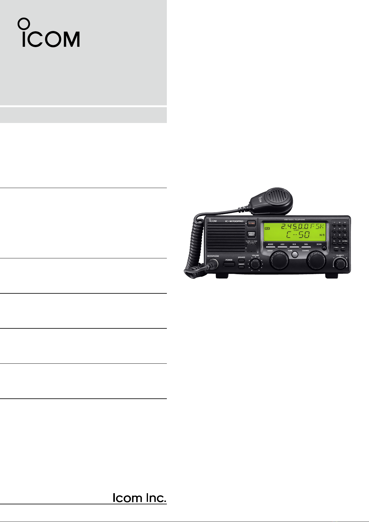
for the IC-M700PRO SSB RADIO TELEPHONE.
EXPLICIT DEFINITIONS
The explicit definitions described below apply to this
instruction manual.
PRECAUTIONS
WORD DEFINITION
RWARNING Personal injury, fire hazard or electric
shock may occur.
CAUTION Equipment damage may occur.
NOTE If disregarded, inconvenience only. No risk
of personal injury, fire or electric shock.
RWARNING! NEVER connect the transceiver di-
rectly to an AC outlet. This may pose a fire hazard or
result in an electric shock.
RWARNING! NEVER mount the transceiver over-
head. The weight of the transceiver is approximately
7.9 kg. (17.4 lb), but its apparent weight will increase
several fold due to wave shocks and vibration. The
transceiver must be mounted on a flat hard surface
only.
NEVER connect a power source of more than 16 V
DC, such as a 24 volt battery. This connection will ruin
the transceiver.
NEVER allow children to play with equipment contain-
ing a radio transmitter.
NEVER expose the transceiver to rain, snow or any
liquids.
NEVER install the IC-M700PRO into a positive-
grounding ship. Such a connection might blow fuses,
and is not usable.
DO NOT use chemical agents such as benzene or al-
cohol when cleaning, as they can damage the trans-
ceiver’s surfaces.
In maritime mobile operation, KEEP the transceiver
and microphone as far away as possible (at least 1 m)
from the magnetic navigation compass to prevent er-
roneous indications.
USE an Icom microphone and/or handset only (sup-
plied or optional). Other brands may have different pin
assignments and may damage the transceiver.
DO NOT use or place the transceiver in areas with
temperatures below –20°C (–4°F) or above +60°C
(+140°F).
DO NOT connect the transceiver to a power source
using reverse polarity. This connection will not only
blow fuses but may also damage the transceiver.
DO NOT place the transceiver in excessively dusty en-
vironments, or in direct sunlight.
DO NOT place the transceiver against walls, or putting
anything on top of the transceiver. This will obstruct
heat dissipation.
DISPOSAL
The crossed-out wheeled-bin symbol on
your product, literature, or packaging re-
minds you that in the European Union, all
electrical and electronic products, batter-
ies, and accumulators (rechargeable bat-
teries) must be taken to designated
collection locations at the end of their working life. Do
not dispose of these products as unsorted municipal
waste. Dispose of them according to the laws in your
area.
Icom, Icom Inc. and the Icom logo are registered trademarks of
Icom Incorporated (Japan) in Japan, the United States, the United
Kingdom, Germany, France, Spain, Russia, Australia, New Zealand,
and/or other countries.
Icom is not responsible for the destruction, damage to, or
performance of any Icom or non-Icom equipment, if the
malfunction is because of:
• Force majeure, including, but not limited to, fires,
earthquakes, storms, floods, lightning, other natural
disasters, disturbances, riots, war, or radioactive
contamination.
• The use of Icom transceivers with any equipment that is
not manufactured or approved by Icom.

ii
TABLE OF CONTENTS
IMPORTANT ······························································ i
PRECAUTIONS·························································· i
EXPLICIT DEFINITIONS············································ i
DISPOSAL·································································· i
TABLE OF CONTENTS ············································ ii
1 OPERATING RULES AND GUIDELINES ··········· 1
2 PANEL DESCRIPTION ·········································2
■Front panel ·························································2
■Display································································4
3 SELECTING A CHANNEL/FREQUENCY ············5
■Memory mode/VFO mode ··································5
■Selecting a channel ············································5
D Scan function·················································6
■Selecting a frequency ········································6
■Resetting the CPU ·············································7
4 RECEIVE AND TRANSMIT ···································8
■Basic voice receive and transmit ························8
■Functions for transmit ·········································8
D Transmit frequency check ·····························8
■Functions for receive ··········································9
D Squelch function ············································9
D Noise blanker·················································9
D AGC OFF function ·········································9
D Clarity control·················································9
■CW operation····················································10
■FSK operation···················································10
5 SET MODE···························································11
■ Set mode operation ··········································11
■ Set mode contents············································11
6 CONNECTIONS AND INSTALLATION···············15
■ Connections on the rear panel ·························15
■ Unpacking·························································15
■ Connector information ······································16
■ Ground connection ···········································18
■ Power source····················································18
■Antenna ····························································19
D MN-100/MN-100L ANTENNA MATCHERS 19
D AT-130 AUTOMATIC ANTENNA TUNER ···19
D Non-Icom tuner············································19
■Mounting···························································20
D Mounting location ········································20
D Mounting example ·······································20
D Transceiver dimensions·······························20
■Disassembling the transceiver··························21
D Opening the case ········································21
■Fuse replacement·············································21
D DC power cable fuse ···································21
D Circuitry fuse················································21
7 TROUBLESHOOTING·········································22
■Specifications ···················································23
8 SPECIFICATIONS AND OPTIONS ·····················23
■Options ·····························································23

1
1OPERATING RULES AND GUIDELINES
❑ CALL PROCEDURES
Calls must be properly identified and time limits must
be respected.
qGive your call sign each time you call another ves-
sel or coast station. If you have no call sign, identify
your vessel name and the name of the licensee.
wGive your call sign at the end of each transmission
that lasts more than 3 minutes.
eYou must break and give your call sign at least once
every 15 minutes. during long ship-to-shore calls.
rKeep your unanswered calls short, less than 30
seconds.
Do not repeat a call for 2 minutes.
tUnnecessary transmissions are not allowed.
❑ PRIORITIES
qRead all rules and regulations pertaining to priori-
ties and keep an up-to-date copy handy. Safety and
distress calls take priority over all others.
wFalse or fraudulent distress calls are prohibited and
punishable by law.
❑ PRIVACY
qInformation overheard but not intended for you can-
not be lawfully used in any way.
wIndecent or profane language is prohibited.
❑ LOGS
qAll distress, emergency and safety calls must be re-
corded in complete detail. Log data activity is usu-
ally recorded in 24 hour time. Universal Time (UTC)
is frequently used.
wAdjustments, repairs, channel frequency changes
and authorized modifications affecting electrical
operation of the equipment must be kept in the
maintenance log; entries must be signed by the au-
thorized licensed technician performing or supervis-
ing the work.
❑ RADIO LICENSES
(1) SHIP STATION LICENSE
You must have a current radio station license before
using the transceiver. It is unlawful to operate a ship
station which is not licensed.
Inquire through your dealer or the appropriate govern-
ment agency for a Ship-Radiotelephone license appli-
cation. This government-issued license states the call
sign which is your craft’s identification for radio pur-
poses.
(2) OPERATOR’S LICENSE
A Restricted Radiotelephone Operator Permit is the li-
cense most often held by small vessel radio operators
when a radio is not required for safety purposes.
The Restricted Radiotelephone Operator Permit must
be posted or be kept with the operator. Only a licensed
radio operator may operate a transceiver.
However, non-licensed individuals may talk over a
transceiver if a licensed operator starts, supervises,
and ends the call, and makes the necessary log en-
tries.
Keep a copy of the current government rules and reg-
ulations handy.

2
2
PANEL DESCRIPTION
■Front panel
q MICROPHONE CONNECTOR (p. 16)
Accepts the supplied microphone or an optional
handset.
☞ NOTE: No audio is output to the speaker when
the microphone or handset is not connected.
w POWER SWITCH [POWER]
Turns power ON or OFF.
e SPEAKER SWITCH [SPEAKER]
Turns the built-in speaker ON or OFF.
• “è” appears in the display while the speaker is turned
OFF.
• Any external speaker connected to the rear panel is not
turned OFF.
r DISPLAY INTENSITY SWITCH [DIMMER]
Turns the display backlighting ON or OFF.
t VOLUME CONTROL [VOLUME]
Adjusts the audio output level.
• No sound is output to the speaker when:
➥A microphone is not connected.
➥The [SQL] switch is turned ON and no signal is being
received.
y GROUP CHANNEL SELECTOR [GROUP]
In the memory mode, selects 1 of 3 channel groups
(“A,” “B” or “C”). (p. 5)
• In the VFO mode, it has no function.
➥Selects an item in the set mode. (p. 11)
u ANTENNA TUNE SWITCH [TUNE] (p. 8)
Tunes the external tuner to the antenna.
• Activates only when an optional antenna tuner such as
Icom’s AT-130 is connected.
☞ NOTE: When selecting “automatic tuning” in the
set mode, pushing this switch is not necessary
to tune the antenna. (p. 11)
i CHANNEL SELECTOR [CHANNEL] (p. 5)
➥In the memory mode, selects an operating chan-
nel within the selected channel group.
• A maximum of 50 channels are available in each
channel group, depending on set mode setting (pgs.
13 and 14).
➥In the VFO mode, changes the operating fre-
quency in 0.1 kHz steps.
• Frequencies selected in the VFO mode are tempo-
rary.
o SCAN SWITCH [SCAN] (p. 6)
Push to toggle the scan ON or OFF.
!0 CLARITY CONTROL [CLARITY] (p. 9)
Shifts the receive frequency ±150 Hz for clear re-
ception of an off frequency signal.
MICROPHONE
POWER
VOLUME
TX FREQ
2182KHz
RESET
MODE
TUNE
SSB RADIO TELEPHONE
AGCSQL SCAN
CLARITY
NB
SPEAKER
[ALARM] [TX FREQ]+
FOR ALARM TX
DIMMER
GROUP CHANNEL
123
456
789
CL
TONLYENT
0CH/FREQ
iM 700PRO
TX
RX
DSC F
ALM
qwer tyui !
0
o
This function is not installed
in the IC-M700PRO.

3
2PANEL DESCRIPTION
!1 KEYPAD
No function*.
Toggles between the memory mode and the
VFO mode. (p. 5)
• This key may be disabled by your dealer.
No function*.
No function*.
No function*.
!2 SQUELCH SWITCH [SQL] (p. 9)
Activates the voice squelch function to reject unde-
sired background noise while no signal is being re-
ceived.
• The squelch opens only when the received signal con-
tains no voice or FSK components.
!3 NOISE BLANKER SWITCH [NB] (p. 9)
Turns the noise blanker function ON to remove
pulse-type noise such as engine ignition noise.
• “NB” appears when the function is turned ON.
!4 AGC OFF SWITCH [AGC] (p. 9)
Deactivates the AGC function to receive weak sig-
nals blocked by strong adjacent signals.
• “ê” appears when the [AGC] switch is turned ON
(stands for AGC deactivated).
!5 MODE SWITCH [MODE]
Temporarily selects an operating mode. Available
modes differ with the transceiver version.
• USB, AM, J2B (AFSK), FSK, R3E and CW modes are
available.
• The temporary mode is cleared and the previous mode
appears when changing a channel.
!6 TRANSMIT FREQUENCY SWITCH [TX FREQ]
(p. 8)
Displays the transmit frequency and opens the
squelch to check and monitor the transmit fre-
quency.
!7 2182 kHz SELECTION SWITCH
[2182KHz • reset ] (p. 5)
➥Selects channel 0 (2182 kHz; distress call fre-
quency).
• The channel selector does not function when select-
ing channel 0.
➥Ignores external control and gives the front
panel control priority when an external control-
ler (NMEA format) is connected.
CH/FREQ
TONLY
ENT
*These keys function in some versions. See the separate
KEYPAD OPERATION and CHANNEL LIST instruction
sheet for operating details.
CL
0
9
to
MICROPHONE
POWER
VOLUME
TX FREQ
2182KHz
RESET
MODE
TUNE
SSB RADIO TELEPHONE
AGCSQL SCAN
CLARITY
NB
SPEAKER
[ALARM] [TX FREQ]+
FOR ALARM TX
DIMMER
GROUP CHANNEL
123
456
789
CL
TONLYENT
0CH/FREQ
iM 700PRO
TX
RX
DSC F
0
ALM
!1
!2!3!4!5!6!7This function is not installed
in the IC-M700PRO.
■Front panel (Continued)

4
2
PANEL DESCRIPTION
■Display
q RECEIVE INDICATOR
Appears while receiving and when the squelch is
open.
w TUNE INDICATOR (p. 8)
Flashes while the connected antenna tuner, such
as Icom’s AT-130, is being tuned.
• Tuning starts when transmitting on a new frequency or
pushing the [TUNE] switch.
e TRANSMIT INDICATOR
Appears when transmitting.
r S/RF METER
➥Shows the relative received signal strength while
receiving.
➥Shows output power while transmitting.
t CHANNEL/VFO INDICATOR (p. 5)
➥Shows the selected group and channel in the
memory mode.
➥“FREQ” appears in the VFO mode.
y SQUELCH INDICATOR (p. 9)
Appears when the squelch is ON.
TUNE
DUP SIMP
TX
RX
SCAN
SQL NB
AGC
AGC
ALM
q
w
e
rt yu
i
o
!0!1!2!3
u SCAN INDICATOR (p. 6)
Appears when the scan function is in use.
• The scan function is not available on some versions.
• Pushing [SCAN] starts and stops the scan.
i NOISE BLANKER INDICATOR (p. 9)
Appears when the [NB] switch is turned ON.
o AGC OFF INDICATOR (p. 9)
Appears when the [AGC] switch is pushed to indi-
cate the AGC function is deactivated.
!0 MODE READOUT
Shows the selected operating mode (type of emis-
sion).
!1 SPEAKER OFF INDICATOR
Appears when the [SPEAKER] switch is pushed to
indicate the front panel speaker is deactivated.
!2 FREQUENCY READOUT
➥ Shows the selected frequency whether in the
memory mode or the VFO mode. (p. 5)
➥Shows the transmit frequency (for duplex
channels) when transmitting or when pushing
[TX FREQ]. (p. 8)
!3 SIMPLEX/DUPLEX INDICATORS
These appear to show whether the selected chan-
nel is simplex or duplex.
• In the VFO mode, only simplex channels are available.
• No indicator means that there is no transmit frequency
programmed.

5
3SELECTING A CHANNEL/FREQUENCY
■Memory mode/VFO mode
The transceiver has 2 operating modes: memory mode
and VFO mode. The memory mode is used to select
preprogrammed marine channels in one of the 3 chan-
nel groups; The VFO mode is used to select frequen-
cies around preprogrammed channels.
Push [CH/FREQ] to toggle between the memory and
VFO modes.
• “FREQ” appears when in the VFO mode.
• In the VFO mode, only simplex operation is possible.
■Selecting a channel
The transceiver has 150 channels divided into 3
groups of 50 channels, maximum. However, the num-
ber of channels in each group can be restricted in the
set mode, depending on your needs. (pgs. 13 and 14)
☞ NOTE: When channel 0 and/or 2182 kHz is se-
lected with the [2182KHz] switch, channel selection
is NOT possible. In such cases, push [2182KHz]
first.
qIf necessary, push [CH/FREQ] to select the mem-
ory mode.
wRotate the [GROUP] selector to select the desired
channel group; then rotate the [CHANNEL] selector
to select the desired channel.
SQL
SIMP
SQL
CH/FREQ
CH/FREQ
Memory mode
VFO mode
SQL
DUP
SQL
SIMP
SQL
Rotate
[GROUP]
to select a
channel group
Group A
Group B
Group C
Rotate
[CHANNEL]
to select a
channel within
a group
Group B, channel 1
Group B, channel 2
Group B, channel 50
DUP
SQL
DUP
SQL
DUP
SQL

6
3
SELECTING A CHANNEL/FREQUENCY
D Scan function
The scan function allows you to automatically search
for signals with a group of channels. There are 2 scan
types (selectable in the set mode) as follows:
Scan operation
qRotate the [GROUP] selector to select the group
you wish to scan.
wIf necessary, push [SQL] to close the squelch.
• “SQL” appears.
ePush [SCAN] to start scanning.
• “SCAN” appears.
rPush [SCAN] again to stop scanning.
• “SCAN” disappears.
Channel scan
ch 1
ch 2 ch 3
ch 4
ch 5ch 50
scan is
cancelled
when
transmitting
Channel resume scan
ch 1
ch 2 ch 3
ch 4
ch 5ch 50
scan pauses
for 10 seconds
after the squelch
opens,
then resumes
■Selecting a frequency
The transceiver has 0.5 to 30.0 MHz general cover-
age receive capability, with 100 Hz resolution. Use the
VFO mode to select frequencies around the prepro-
grammed channels in the memory mode.
☞ NOTE: Frequencies selected in the VFO mode are
for temporary use and are not stored in memory.
qWhile in the memory mode, rotate the [GROUP]
and [CHANNEL] selectors to select the channel
nearest the frequency you want.
wPush [CH/FREQ] to select the VFO mode.
• “FREQ” appears.
eRotate the [CHANNEL] selector to select the de-
sired frequency.
• The frequency changes in 100 Hz steps.
Rotate
[CHANNEL]
to select a
frequency in
100 Hz steps
1.6 MHz selected
1.6001 MHz selected
SIMP
SQL
SIMP
SQL

7
3SELECTING A CHANNEL/FREQUENCY
■Resetting the CPU
Under some circumstances, the transceiver’s internal
CPU may cause erroneous indications on the display.
If this happens, reset the CPU as follows:
While pushing [ENT] and [0], push [POWER] to turn
power ON.
• The CPU is reset and the display at right appears.
CAUTION: Resetting the CPU returns the set mode
contents to their default values.
SIMP
RX
Group A, channel 1 is
selected after resetting
the CPU.

8
4
RECEIVE AND TRANSMIT
■Basic voice receive and transmit
qCheck the following in advance:
➥The microphone is connected.
➥The [SPEAKER] switch is turned OFF.
➥The [SQL] switch is turned OFF.
➥The [CLARITY] control is set to the center posi-
tion.
➥The memory mode is selected.
• If necessary, push [CH/FREQ] to select the memory
mode.
wSelect the desired channel to be received with the
[GROUP] and [CHANNEL] selectors.
• When receiving a signal, the S-meter shows the signal
strength.
eAdjust [VOLUME] to the desired audio level when
receiving a signal.
rIf the received signal is in a different mode, push
[MODE] to select the desired operating mode.
tIf connected, push [TUNE] to tune the antenna
tuner.
• This operation is not necessary when “automatic tun-
ing” is selected in the set mode (p. 11).
yTo transmit on the channel, push and hold the PTT
switch on the microphone.
• “TUNE” flashes for 1 to 2 seconds for the first trans-
mission on a channel when an antenna tuner is con-
nected.
uAfter the flashing stops, speak into the microphone
at your normal voice level.
• The RF meter shows the output power, according to
your voice level.
iRelease the PTT switch to return to receive.
microphone
connector
[SQL]
[SPEAKER] [CLARITY]
■Functions for transmit
D Transmit frequency check
When “DUP” appears on the display, such as for a
ship-to-shore channel, the transmit frequency differs
from the receive frequency.
In such cases, the transmit frequency should be mon-
itored before transmitting to prevent interference to
other stations.
Push and hold [TX FREQ] to monitor the transmit fre-
quency.
• The display shows the transmit frequency.
TX FREQ

9
4RECEIVE AND TRANSMIT
■Functions for receive
D Squelch function
The squelch function detects signals with voice com-
ponents and squelches (mutes) unwanted signals,
such as unmodulated beat signals. This provides
quiet standby.
When you need to receive weak signals, the squelch
should be turned OFF.
Push [SQL] to toggle the function ON or OFF.
• “SQL” appears when the squelch function is turned ON.
DUP
SQL
D Noise blanker
The noise blanker function reduces pulse type noise,
such as that coming from engine ignitions.
The noise blanker may distort reception of strong
signals. In such cases, the noise blanker should be
turned OFF.
Push [NB] to toggle the function ON or OFF.
• “NB” appears when the noise blanker function is turned
ON.
DUP
RX
NB
D AGC OFF function
The receiver gain is automatically adjusted accord-
ing to the received signal strength with the AGC (Au-
tomatic Gain Control) function, to prevent distortion
from strong signals and to obtain a constant output
level.
When receiving weak signals with adjacent strong
signals or noise, the AGC function may reduce the
sensitivity. In this situation, the AGC function should
be deactivated.
Push [AGC] to toggle the function ON or OFF.
• “ê” appears when the AGC function is deactivated.
DUP
RX
AGC
AGC
D Clarity control
Voice signals received from other stations may be
difficult to receive. This may sometimes happen if a
station is transmitting slightly off frequency. In such
cases, vary the receive frequency only, using the
[CLARITY] control.
Adjust [CLARITY] to improve the audio signal.
[CLARITY]

10
4
RECEIVE AND TRANSMIT
■CW operation
The transceiver has the following CW keying features
selectable in the set mode, as described on page
12.
➥Full break-in (receiving is possible while transmitting)
➥Semi break-in (automatic transmission with keying)
➥OFF (manual transmission is necessary before keying)
qConnect a CW keyer or an external electronic
keyer to the ACC(1) socket, as shown at right.
wSelect the desired channel to operate in the CW
mode.
eWhen the selected channel is not in the CW mode,
push [MODE] one or more times to select “CW.”
rOperate the CW keyer to transmit a CW signal.
☞ NOTE:
➥CW mode is not available in some versions.
➥CW narrow can be selected in the set mode
when an optional filter is installed. (p. 12)
CW key connection
2
8
45
13
67
ACC(1) socket
pin 1
pin 2
CW key
■FSK operation
The transceiver has FSK and J2B modes for FSK op-
eration—use FSK when using the built-in oscillator;
use J2B when using an AFSK terminal unit.
qConnect an FSK terminal unit as shown at right.
wSelect the desired channel.
• FSK channels are available, depending on the ver-
sion.
ePush [MODE] one or more times to select either
“FSK” or “J2B.”
rOperate the FSK terminal unit.
☞ NOTE:
➥FSK shift frequency and FSK polarity can be
adjusted in the set mode (p. 12).
➥Some transceivers may operate 1.7 kHz higher
than the IC-M700PRO’s J2B mode, even when
the same displayed frequencies are in use.
FSK terminal unit connection
2
8
45
13
67
ACC(1) socket
FSK terminal unit
FSK keying
AF input
Tx/Rx control
Ground
pin 3
pin 4
pins 2, 5

11
5SET MODE
■ Set mode operation
Set mode operation is used for programming infre-
quently changed values or functions.
☞ NOTE: Some of the set mode items described in
this section are not available on some transceiver
versions.
qIf necessary, push [POWER] to turn power OFF.
wWhile pushing [ENT] and [1], push [POWER] to turn
power ON and enter the set mode.
eRotate the [GROUP] selector to select the desired
item.
rRotate the [CHANNEL] selector to set the values or
options for the selected item.
tTurn power OFF and then ON again to exit the set
mode.
[POWER]
Status
Item
[ENT][1]
(1) Antenna tuner
The transceiver has several tuner control systems for
use with an optional Icom antenna tuner. Select the
condition, depending on the antenna tuner you are
using.
☞ NOTE: An internal switch selection may be re-
quired when using a non-Icom tuner (p. 19).
AT-130
(default)
AT-120
AH-3
(2) Automatic tuning operation
When the optional AT-130 automatic antenna tuner is
connected, tuning can be started automatically with-
out the [TUNE] switch, for instant operation.
If manual tuning is required, this automatic operation
can be deactivated.
Tuning starts when pushing
[PTT] on a new frequency.
Tuning starts only when
[TUNE] is pushed.
(default)
(3) Scan type selection
This item sets scan to function as “channel scan” or
“channel resume scan.”
Both channel scan and channel resume scan search
around a user selected channel or search in the band
when a channel is selected.
Channel scan
Scan is canceled when
transmitting.
Channel resume scan
Scan pauses when squelch
opens, then resumes after
10 seconds.
(default)
■ Set mode contents

12
5
SET MODE
(4) Scan speed
Selects scan speed as follows:
(unit: sec./ch)
Faster Slower
Fastest scan speed
(default)
Slowest scan speed
(5) CW/FSK narrow filter
This selects the passband width for CW (A1A), FSK
or J2B mode.
☞ NOTE: When “ON” is selected without the optional
filter installed, the transceiver does not function in
these modes.
Passband:
2.3 kHz/ 6 dB
(default)
Passband:
500 Hz/ 6 dB
(6) FSK frequency shift
Several shift settings (the difference between the
mark and space frequency) are used for FSK opera-
tion. This item allows you to select a shift setting for
almost any FSK system.
(7) FSK polarity
Normal and reverse polarities are available for FSK
operation. This item allows you to select one of these
polarities.
“FK-REV OFF” (normal):
key open (mark); key close (space)
“FK-REV ON” (reverse):
key open (space); key close (mark)
Frequency shift:
170 Hz
(default)
Frequency shift:
425 Hz
Frequency shift:
850 Hz
FSK normal
(default)
FSK reverse
(8) CW break-in
The CW break-in function (in A1A mode) toggles
transmit and receive with CW keying. Full break-in al-
lows you to receive signals between transmitted key-
ing pulses during CW transmission. Semi break-in
allows you to mute receiving until keying stops with
a delay time.
Full break-in
Automatic keying without
delay time (default)
Semi break-in
Automatic keying with delay
time
OFF
Manual transmission
necessary for keying
2 3 4 5 6 7 8 9 10
2 3 4 5 6 7 8 9 10

13
5SET MODE
(9) LCD contrast
The LCD contrast can be adjusted through 10 levels,
to suit transceiver mounting angle, location and am-
bient lighting.
Lowest contrast
Highest contrast
(default: 7)
(10) ID number setting for remote control
When connecting an external controller, such as a
personal computer, 2-digit ID codes are required to
access the transceiver. The IC-M700PRO adopts the
NMEA0183 format, and uses a “proprietary sentence”
for remote control.
NMEA ID: 1
NMEA ID: 99
(default: 2)
(11) Remote control input terminal
Remote control signals can be input via the [RE-
MOTE] socket or [CLONE] jack.
The [REMOTE] socket
(default)
The [CLONE] jack
(12) Display backlighting
Allows you to select 1 of 4 intensity levels for the dis-
play backlighting.
Dimmest
(default)
Brightest
(13) Group A channel inhibit
This item allows you to set the number of usable
channels in channel group A, up to a maximum of 50
channels.
Minimum number of
channels set for
Group A: 1
Maximum number of
channels set for
Group A: 50 (default)

14
5
SET MODE
(14) Group B channel inhibit
This item allows you to set the number of usable
channels in channel group B, up to a maximum of 50
channels.
Minimum number of
channels set for
Group B: 1
Maximum number of
channels set for
Group B: 50 (default)
(15) Group C channel inhibit
This item allows you to set the number of usable
channels in channel group C, up to a maximum of 50
channels.
Minimum number of
channels set for
Group C: 1
Maximum number of
channels set for
Group C: 50 (default)

15
6CONNECTIONS AND INSTALLATION
u TUNER RECEPTACLE
Connects a control cable to an optional AT-130 an-
tenna tuner. A female connector is supplied for
connection.
i DC POWER RECEPTACLE
Connects to a regulated 12–16 V DC power source
such as a 12 V battery or DC power supply using
the supplied DC power cable.
CAUTION: DO NOT connect to a 24 V battery.
This will damage the transceiver.
q ANTENNA CONNECTOR (p. 19)
Connects a 50 øHF band antenna with a 50 ø
matched coaxial cable and a PL-259 plug.
w GROUND TERMINAL
IMPORTANT! Connects to a ship’s (or vehicle’s)
ground. See p. 18 for details.
e ACC(1) and ACC(2) SOCKETS
See p. 16 for details.
r CLONE JACK
For Dealer use only.
t REMOTE SOCKET (p. 17)
REMOTE socket for Marine and General versions.
y EXTERNAL SPEAKER JACK
Connects a 4 to 8 øexternal speaker using a 1⁄4”
monaural plug. This external audio is not muted by
the [SPEAKER] switch on the front panel.
Optional AT-130
External
speaker
q
wrty
u
i
e
12 V battery
RCAUTION:
NEVER remove the
line fuse from the DC
power cable.
■ Unpacking
Microphone (HM-180) ············································ 1
Microphone hanger ················································ 1
DC power cable (OPC-1107A) ······························ 1
Mounting bracket ··················································· 1
Cushion rubber ······················································ 4
Bracket knobs (8820000170) ································ 4
Flat washer (M5) ···················································· 4
CONNECTORS
DIN connector (8-pin for ACC1) ····························· 1
DIN connector (7-pin for ACC2) ····························· 1
Speaker plug (5610000440) ·································· 1
Tuner connector (5610000150) ····························· 1
Pins for tuner connector (5610000160) ·················· 4
Plates for tuner connector (6910009540) ··············· 4
NUTS AND BOLTS
Allen bolt (M6 ×50) ··············································· 4
Self-tapping screws (M6 ×30) ······························· 4
Nuts (M6; use 2 pcs. for each bolt) ························ 8
Flat washers (M6) ·················································· 8
Spring washers (M6) ············································· 4
Self-tapping screws
(M3 ×16 for mic. hanger) ······························· 2
FUSES
DC power cable (30 A) ·········································· 1
1205 (internal) ······················································· 2
■ Connections on the rear panel

16
6
CONNECTIONS AND INSTALLATION
■ Connector information
ACC(1) PIN PIN NAME DESCRIPTION SPECIFICATIONS
1CWK CW and FSK keying input. Input level: Less than 0.6 V for transmit.
2 GND Connects to ground. Connected in parallel with ACC(2) pin 2.
3 SEND
Input/output pin.
Goes to ground when transmitting.
When grounded, transmits.
Ground level: –0.5 to 0.8 V
Input current: Less than 20 mA
Connected in parallel with ACC(2) pin 3.
4 MOD Modulator input.
Usable when pin 3 is grounded.
Input impedance: 10 kø
Input level: Approx. 100 mV rms
5 AF AF detector output.
Fixed, regardless of the [AF] position.
Output impedance: 4.7 kø
Output level: 100–300 mV rms
6NC No connection.
7 13.6 V 13.6 V output when power is ON. Output current: Max. 1 A
Connected in parallel with ACC(2) pin 7.
8 ALC ALC voltage input.
Control voltage: –3 to 0 V
Input impedance: More than 10 kø
Connected in parallel with ACC(2) pin 5.
2
8
45
13
67
ACC(2) PIN PIN NAME DESCRIPTION SPECIFICATIONS
2 GND Same as ACC(1) pin 2.
3 SEND Same as ACC(1) pin 3.
1 8 V Regulated 8 V output. Output voltage: 8 V ±0.3 V
Output current: Less than 10 mA
4NC No connection.
5 ALC Same as ACC(1) pin 8.
6 RLC T/R relay control output. When transmitting: 0 V (less than 0.5 A)
7 13.6 V Same as ACC(1) pin 7.
2
45
13
67
MICROPHONE PIN NAME DESCRIPTION SPECIFICATIONS
2NC No connection.
1 MIC+ Audio input from the microphone
element. Input impedance: 600 ø
4 AF2 AF input.
Connected to pin 3 in the microphone.
5 PTT PTT switch input. When grounded, transmits.
6 GND Connected to ground.
3 AF1 AF output controlled with [VOLUME].
Connected to pin 4 in the microphone. Output impedance: 4 ø
7 MIC– Coaxial ground for MIC+.
8 AF– Coaxial ground for AF1 and AF2.
1
7
6
54
3
8
2
PIN
TUNER PIN NAME DESCRIPTION SPECIFICATIONS
1 KEY Key signal input. –0.5 to 0.8 V during tuning
4E_terminal Ground
2 START Start signal output. Pulled up 8 V, 0 V(100 msec) as start signal.
3 13.6V 13.6 V output Max. current:2A
12
34
PIN

6CONNECTIONS AND INSTALLATION
17
REMOTE PIN PIN NAME DESCRIPTION SPECIFICATIONS
2 MOD– Coaxial ground for MOD+.
1 MOD+ Modulation input from an external
terminal unit.
Input impedance: 600 ø
Input level:Approx. 1.3 mV rms
4 AF– Coaxial ground for AF+.
5 NMI+ NMEA data input. NMEA standard format/level
6 NMI– Coaxial ground for NMI+.
7 NMO+ NMEA data output. NMEA standard format/level
3 AF+ AF detector output for an external
terminal unit.
Output impedance: 600 ø
Output level: 0.25–2.5 V rms
8 NMO– Coaxial ground for NMO+.
9 GND Ground for digital equipment.
69
51
DC 13.6V PIN NAME DESCRIPTION SPECIFICATIONS
1–3 + +DC input
4–6 –_DC input
PIN
Max. power consumption: 30 A
1 2
4 6
3
5
■ Connector information (Continued)
Other manuals for IC-M700PRO
4
Table of contents
Other Icom Telephone manuals