Icom IC-M700PRO User manual

INSTRUCTION MANUAL
SSB RADIO TELEPHONE
iM700PRO

ii
IMPORTANT
READ THIS INSTRUCTION MANUAL CAREFULLY
before attempting to operate the transceiver.
SAVE THIS INSTRUCTION MANUAL—This manual
contains important safety and operating instructions for
the IC-M700PRO SSB RADIO TELEPHONE.
EXPLICIT DEFINITIONS
The explicit definitions described below apply to this
instruction manual.
PRECAUTIONS
WORD DEFINITION
RWARNING Personal injury, fire hazard or electric
shock may occur.
CAUTION Equipment damage may occur.
NOTE If disregarded, inconvenience only. No risk
of personal injury, fire or electric shock.
RWARNING! NEVER connect the transceiver to an
AC outlet directly. This may pose a fire hazard or re-
sult in an electric shock.
RWARNING! NEVER mount the transceiver over-
head. The weight of the transceiver is approximately 8
kg., but its apparent weight will increase several fold
due to wave shocks and vibration. The transceiver
must be mounted on a flat hard surface only.
NEVER connect a power source of more than 16 V DC
such as a 24 volt battery. This connection will ruin the
transceiver.
NEVER allow children to play with equipment contain-
ing a radio transmitter.
NEVER expose the transceiver to rain, snow or any
liquids.
NEVER install the IC-M700PRO into a plus-grounding
ship. Such a connection might blow fuses and is not
usable.
DO NOT use chemical agents such as benzene or al-
cohol when cleaning, as they can damage the trans-
ceiver’s surfaces.
In maritime mobile operation, KEEP the transceiver
and microphone as far away as possible (at least 1 m)
from the magnetic navigation compass to prevent er-
roneous indications.
USE an Icom microphone and/or handset only (sup-
plied or optional). Other brands may have different pin
assignments and may damage the transceiver.
AVOID using or placing the transceiver in areas with
temperatures below –20°C (–4°F) or above +60°C
(+140°F).
AVOID connecting the transceiver to a power source
using reverse polarity. This connection will not only
blow fuses but may also damage the transceiver.
AVOID placing the transceiver in excessively dusty en-
vironments or in direct sunlight.
AVOID placing the transceiver against walls or putting
anything on top of the transceiver. This will obstruct
heat dissipation.

iii
IN CASE OF EMERGENCY (for maritime operation)
VERSIONS
Version Description
Marine 2182 kHz 2-tone alarm is built-in.
FSK/CW narrow filter is optional.
All SSB/FSK channels available.
General 2182 kHz 2-tone alarm is optional.
No transmit frequency programming
allowed.
If your vessel requires assistance, contact other ves-
sels and the Coast Guard by sending a distress call on
2182 kHz.
The following versions are available for the
IC-M700PRO.
➀Push [2182kHz] to select the emergency fre-
quency.
➁Push [ALARM] and [TX FREQ] for 1 sec. to trans-
mit a 2-tone alarm signal for at least 30 sec.
•The transceiver automatically stops the alarm after 50
sec.
➂Push [ALARM] to turn the alarm transmission off,
then push and hold the PTT switch on the micro-
phone and send the following information:
1. “MAYDAY, MAYDAY, MAYDAY.”
2. “THIS IS . . . . . . . . . . . . . ”(name of vessel)
3. “LOCATED AT . . . . . . . . . ”(vessel’s position)
4. Give the reason for the distress call.
5. Explain what assistance you need.
6. Give additional information:
•Vessel type
•Vessel length
•Vessel color
•Number of people onboard.

iv
TABLE OF CONTENTS
IMPORTANT . . . . . . . . . . . . . . . . . . . . . . . . . . . . . . ii
EXPLICIT DEFINITIONS . . . . ii
PRECAUTIONS . . . . . . . . . . . . . . . . . . . . . . . . . . . . ii
IN CASE OF EMERGENCY . . . . . . . . . . . . . . . . . . iii
VERSIONS . . . . . . . . . . . . . . . . . . . . . . . . . . . . . . . iii
TABLE OF CONTENTS . . . . . . . . . . . . . . . . . . . . . iv
1 OPERATING RULES AND GUIDELINES . . . . . . 1
2 PANEL DESCRIPTION . . . . . . . . . . . . . . . . . . 2–4
■Front panel . . . . . . . . . . . . . . . . . . . . . . . . . . . . 2
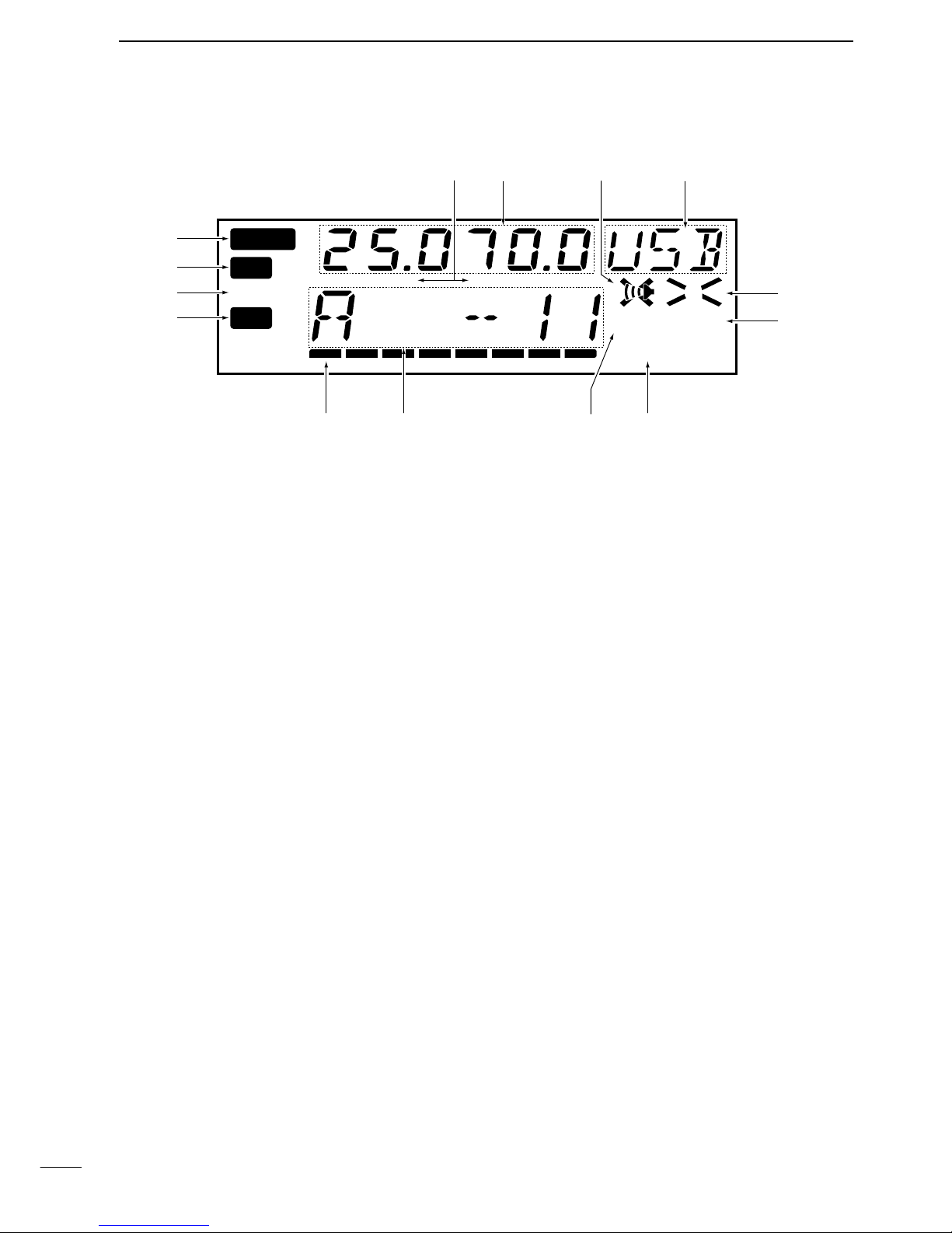
■Display . . . . . . . . . . . . . . . . . . . . . . . . . . . . . . . 4
3 SELECTING A CHANNEL/FREQUENCY . . . . 5–7
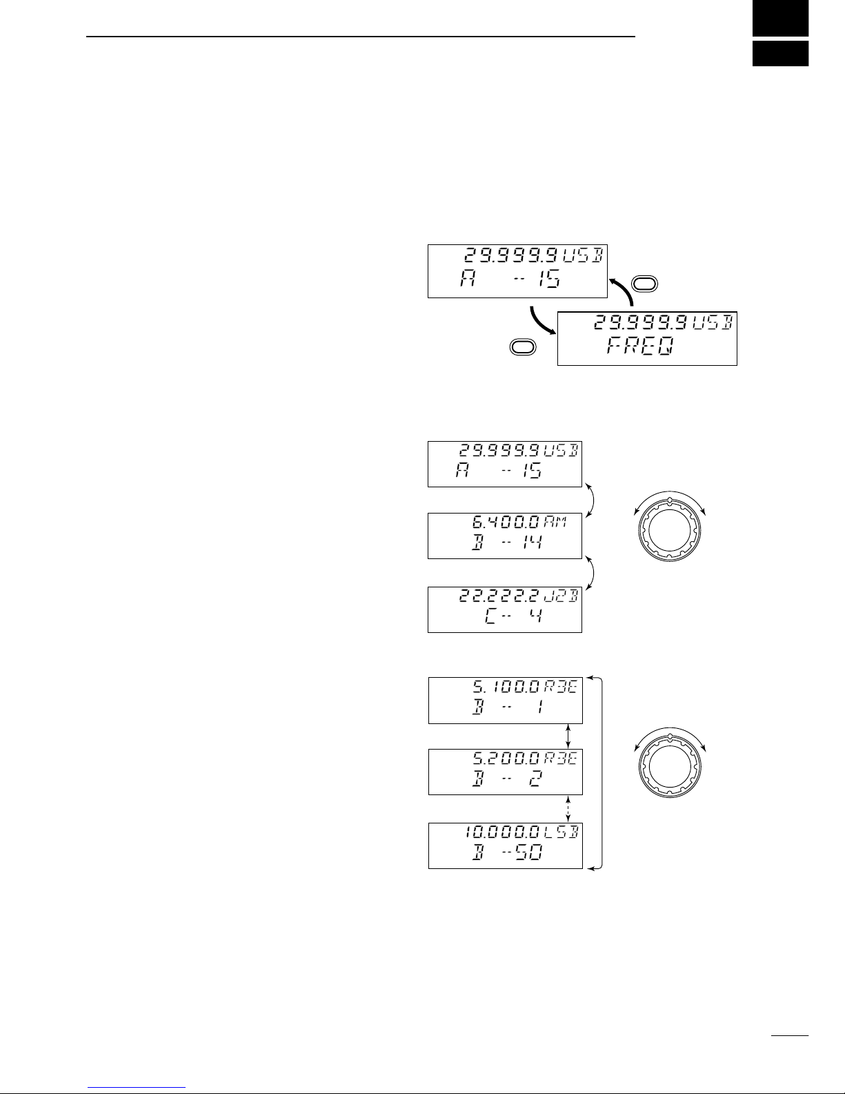
■Memory mode/VFO mode . . . . . . . . . . . . . . . . 5
■Selecting a channel . . . . . . . . . . . . . . . . . . . . . 5
DScan function . . . . . . . . . . . . . . . . . . . . . . . . . . . . . 6
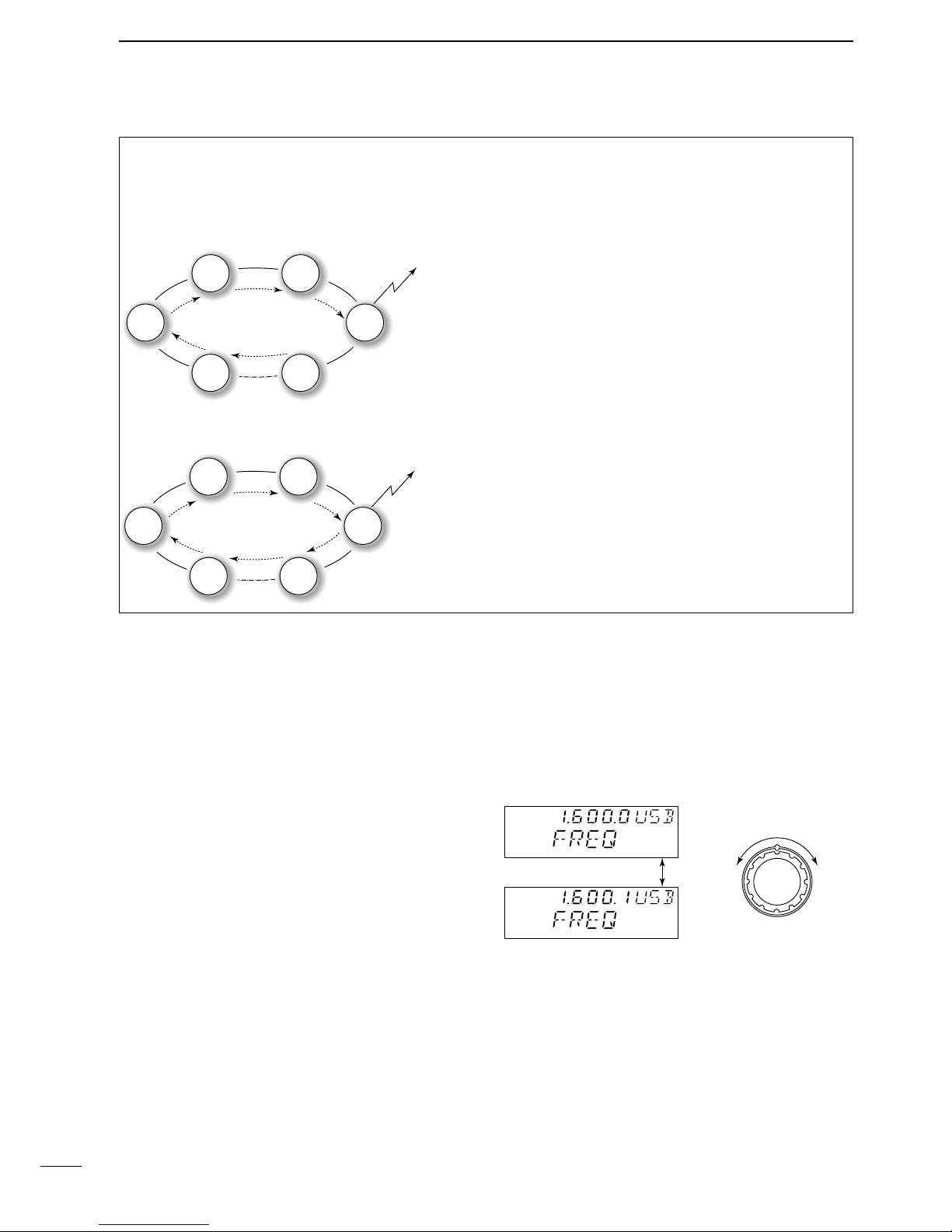
■Selecting a frequency . . . . . . . . . . . . . . . . . . . . 6
■Resetting the CPU . . . . . . . . . . . . . . . . . . . . . . 7
4 RECEIVE AND TRANSMIT . . . . . . . . . . . . . . 8–10
■Basic voice receive and transmit . . . . . . . . . . . 8
■Functions for transmit . . . . . . . . . . . . . . . . . . . . 8
DTransmit frequency check . . . . . . . . . . . . . . . . . . . 8
■Functions for receive . . . . . . . . . . . . . . . . . . . . 9
DSquelch function . . . . . . . . . . . . . . . . . . . . . . . . . . 9
DNoise blanker . . . . . . . . . . . . . . . . . . . . . . . . . . . . . 9
DAGC off function . . . . . . . . . . . . . . . . . . . . . . . . . . . 9
DClarity control . . . . . . . . . . . . . . . . . . . . . . . . . . . . . 9
■CW operation . . . . . . . . . . . . . . . . . . . . . . . . . 10
■FSK operation . . . . . . . . . . . . . . . . . . . . . . . . . 10
5 SET MODE . . . . . . . . . . . . . . . . . . . . . . . . . . 11–14
■Set mode operation . . . . . . . . . . . . . . . . . . . . . 11
■Set mode contents . . . . . . . . . . . . . . . . . . . . . 11
6 CONNECTIONS AND INSTALLATION . . . . 15–21
■Connections on rear panel . . . . . . . . . . . . . . . 15
■Unpacking . . . . . . . . . . . . . . . . . . . . . . . . . . . . 15
■Connector information . . . . . . . . . . . . . . . . . . 16
■Ground connection . . . . . . . . . . . . . . . . . . . . . 18
■Power source . . . . . . . . . . . . . . . . . . . . . . . . . 18
■Antenna . . . . . . . . . . . . . . . . . . . . . . . . . . . . . 19
DMN-100/MN-101L . . . . . . . . . . . . . . . . . . . . . . . . 19
DAT-130 . . . . . . . . . . . . . . . . . . . . . . . . . . . . . . . . . 19
DNon-Icom tuner . . . . . . . . . . . . . . . . . . . . . . . . . . 19
■Mounting . . . . . . . . . . . . . . . . . . . . . . . . . . . . . 20
DMounting location . . . . . . . . . . . . . . . . . . . . . . . . . 20
DMounting example . . . . . . . . . . . . . . . . . . . . . . . . 20
DTransceiver dimensions . . . . . . . . . . . . . . . . . . . . 20
■Installing internal options . . . . . . . . . . . . . . . . 21
DOpening the case . . . . . . . . . . . . . . . . . . . . . . . . . 21
DInstalling an optional filter and alarm unit . . . . . . 21
■Fuse replacement . . . . . . . . . . . . . . . . . . . . . . 21
7 TROUBLESHOOTING . . . . . . . . . . . . . . . . . . . . 22
8 SPECIFICATIONS AND OPTIONS . . . . . . . . . . 23
■Specifications . . . . . . . . . . . . . . . . . . . . . . . . . 23
■Options . . . . . . . . . . . . . . . . . . . . . . . . . . . . . . 23

1
1
OPERATING RULES AND GUIDELINES
❑CALL PROCEDURES
Calls must be properly identified and time limits must
be respected.
➀Give your call sign each time you call another vessel
or coast station. If you have no call sign, identify
your vessel name and the name of the licensee.
➁Give your call sign at the end of each transmission
that lasts more than 3 min.
➂You must break and give your call sign at least once
every 15 min. during long ship-to-shore calls.
➃Keep your unanswered calls short, less than 30 sec.
Do not repeat a call for 2 min.
➄Unnecessary transmissions are not allowed.
❑PRIORITIES
➀Read all rules and regulations pertaining to priorities
and keep an up-to-date copy handy. Safety and dis-
tress calls take priority over all others.
➁False or fraudulent distress calls are prohibited and
punishable by law.
❑PRIVACY
➀Information overheard but not intended for you can-
not be lawfully used in any way.
➁Indecent or profane language is prohibited.
❑LOGS
➀All distress, emergency and safety calls must be
recorded in complete detail. Log data activity is usu-
ally recorded in 24 hour time. Universal Time (UTC)
is frequently used.
➁Adjustments, repairs, channel frequency changes
and authorized modifications affecting electrical op-
eration of the equipment must be kept in the main-
tenance log; entries must be signed by the
authorized licensed technician performing or super-
vising the work.
❑RADIO LICENSES
(1) SHIP STATION LICENSE
You must have a current radio station license before
using the transceiver. It is unlawful to operate a ship
station which is not licensed.
Inquire through your dealer or the appropriate govern-
ment agency for a Ship-Radiotelephone license appli-
cation. This government-issued license states the call
sign which is your craft’s identification for radio pur-
poses.
(2) OPERATOR’S LICENSE
A Restricted Radiotelephone Operator Permit is the li-
cense most often held by small vessel radio operators
when a radio is not required for safety purposes.
The Restricted Radiotelephone Operator Permit must
be posted or be kept with the operator. Only a licensed
radio operator may operate a transceiver.
However, non-licensed individuals may talk over a
transceiver if a licensed operator starts, supervises,
and ends the call, and makes the necessary log en-
tries.
Keep a copy of the current government rules and reg-
ulations handy.

2
2PANEL DESCRIPTION
■Front panel
qMICROPHONE CONNECTOR (p. 16)
Accepts the supplied microphone or an optional
handset.
☞NOTE: No audio is output via the speaker when the
microphone or handset is not connected.
wPOWER SWITCH [POWER]
Turns power on and off.
eSPEAKER SWITCH [SPEAKER]
Turns the built-in speaker on and off.
•“è”appears in the display while the speaker is turned
off.
•Any external speaker connected to the rear panel is not
turned off.
rDISPLAY INTENSITY SWITCH [DIMMER]
Turns the display backlighting on and off.
tVOLUME CONTROL [VOLUME]
Adjusts the audio output level.
•Audio does not come from the speaker when:
➟A microphone is not connected.
➟The [SQL] switch is turned on and no signal is being
received.
yGROUP CHANNEL SELECTOR [GROUP]
➥In memory mode, selects 1 of 3 channel groups
(“A,”“B”or “C”). (p. 5)
•In VFO mode, no function.
➥Selects an item in set mode. (p. 11)
uANTENNA TUNE SWITCH [TUNE] (p. 8)
Tunes the connected tuner to the antenna.
•Activates only when an optional antenna tuner such as
Icom’s AT-130 is connected.
☞NOTE: When selecting “automatic tuning”in set
mode, pushing this switch is not necessary to tune
the antenna. (p. 11)
iCHANNEL SELECTOR [CHANNEL] (p. 5)
➥In memory mode, selects an operating channel
within the selected channel group.
•A maximum of 50 channels are available in each
channel group depending on set mode setting (pgs.
13, 14).
➥In VFO mode, changes the operating frequency
in 0.1 kHz steps.
•Frequencies selected in VFO mode are temporary.
oSCAN SWITCH [SCAN] (p. 6)
Push to toggle scan on and off.
!0 CLARITY CONTROL [CLARITY] (p. 9)
Shifts the receive frequency ±150 Hz for clear re-
ception of an off frequency signal.
MICROPHONE
POWER
VOLUME
ALARM
TX FREQ
2182KHz
RESET
MODE
TUNE
SSB RADIO TELEPHONE
AGC SQL SCAN
CLARITY
NB
SPEAKER
[ALARM] [TX FREQ]+
FOR ALARM TX
DIMMER
GROUP CHANNEL
123
456
789
CL
T ONLY ENT
0CH/FREQ
iM 700PRO
TUNE DUP SIMP
TX
RX
DSC FSCAN
SQL N B
A43210
ALM
AGCAGC
q w e r t y u i !0
!1
o
!2!3!4!5!6!7!8

3
2
PANEL DESCRIPTION
!1 KEYPAD
No function*.
Toggles between memory mode and VFO
mode. (p. 5)
•This key may be disabled by your dealer.
No function*.
No function*.
No function*.
!2 SQUELCH SWITCH [SQL] (p. 9)
Activates the voice squelch function to reject unde-
sired background noise while no signal is being re-
ceived.
•The squelch opens only when the received signal con-
tains no voice or FSK components.
!3 NOISE BLANKER SWITCH [NB] (p. 9)
Turns the noise blanker function on to remove
pulse-type noise such as engine ignition noise.
•“NB”appears when the function is turned on.
!4 AGC OFF SWITCH [AGC] (p. 9)
Deactivates the AGC function to receive weak sig-
nals blocked by strong adjacent signals.
•“ê”appears when the [AGC] switch is turned on
(stands for AGC deactivated).
!5 MODE SWITCH [MODE]
Selects an operating mode temporarily. Available
modes differ with version.
•USB, AM, J2B (AFSK), FSK, R3E and CW modes are
available.
•The temporary mode is cleared and the previous mode
appears when changing a channel.
!6 TRANSMIT FREQUENCY SWITCH [TX FREQ]
(p. 8)
Displays the transmit frequency and opens the
squelch to check and monitor the transmit fre-
quency.
!7 2182 kHz SELECTION SWITCH
[2182kHz •
RESET
] (p. iii)
➥Selects channel 0 (2182 kHz; distress call fre-
quency).
•The channel selector does not function when select-
ing channel 0.
➥Ignores external control and gives the front panel
control priority when an external controller
(NMEA format) is connected.
0
9
to
ENT
T ONLY
CH/FREQ
CL
!8 ALARM SWITCH [ALARM] (p. iii)
➥Emits a distress alarm signal from the speaker.
➥Transmits a distress alarm or alarm testing signal
when pushed together with the [TX FREQ]
switch.
☞NOTE: General versions are not equipped with this
[ALARM] switch.
*These keys function in some versions. See the separate
KEYPAD OPERATION and CHANNEL LIST instruction
sheet for operating details.

4
2PANEL DESCRIPTION
■Display
qALARM INDICATOR (p. iii)
Appears when the alarm function is activated such
as for an alarm test or distress alarm transmission.
•Not available in General version.
wRECEIVE INDICATOR
Appears while receiving and when the squelch is
open.
eTUNE INDICATOR (p. 8)
Flashes while the connected antenna tuner, such as
Icom’s AT-130, is being tuned.
•Tuning starts when transmitting on a new frequency or
pushing the [TUNE] switch.
rTRANSMIT INDICATOR
Appears when transmitting.
tS/RF METER
➥Shows the relative received signal strength while
receiving.
➥Shows output power while transmitting.
yCHANNEL/VFO INDICATOR (p. 5)
➥Shows the selected group and channel in mem-
ory mode.
➥“FREQ”appears in VFO mode.
uSQUELCH INDICATOR (p. 9)
Appears when the squelch is on.
TUNE DUP SIMP
TX
RX
SCAN
SQL N B
AGCAGC
ALM
q
w
e
r
ty ui
o
!0
!1!2!3!4
iSCAN INDICATOR (p. 6)
Appears when the scan function is in use.
•The scan function is not available on some versions.
•Pushing [SCAN] starts and stops scan.
oNOISE BLANKER INDICATOR (p. 9)
Appears when the [NB] switch is turned on.
!0 AGC OFF INDICATOR (p. 9)
Appears when the [AGC] switch is pushed to indi-
cate the AGC function is deactivated.
!1 MODE READOUT
Shows the selected operating mode (type of emis-
sion).
!2 SPEAKER OFF INDICATOR
Appears when the [SPEAKER] switch is pushed to
indicate the front panel speaker is deactivated.
!3 FREQUENCY READOUT
➥Shows the selected frequency whether in mem-
ory mode or VFO mode. (p. 5)
➥Shows the transmit frequency (for duplex chan-
nels) when transmitting or when pushing [TX
FREQ]. (p. 8)
!4 SIMPLEX/DUPLEX INDICATORS
These appear to show whether the selected chan-
nel is simplex or duplex.
•In VFO mode, only simplex channels are available.
•No indicator means that there is no transmit frequency
programmed.

5
3
SELECTING A CHANNEL/FREQUENCY
■Memory mode/VFO mode
The transceiver has 2 operating modes: memory mode
and VFO mode. Memory mode is used to select pre-
programmed marine channels in one of the 3 channel
groups; VFO mode is used to select frequencies
around preprogrammed channels.
Push [CH/FREQ] to toggle between memory and VFO
modes.
•“FREQ”appears when in VFO mode.
•In VFO mode only simplex operation is possible.
■Selecting a channel
The transceiver has 150 channels divided into 3
groups of 50 (max.) channels. However, the number of
channels in each group can be restricted in set mode
(pgs. 13, 14) depending on your needs.
☞NOTE: When channel 0 and/or 2182 kHz is se-
lected with the [2182KHz] switch, channel selection
is NOT possible. In such cases, push [2182KHz] in
advance.
➀Push [CH/FREQ] to select memory mode, if neces-
sary.
➁Rotate the [GROUP] selector to select the desired
channel group; then rotate the [CHANNEL] selector
to select the desired channel.
SQL
SIMP
SQL
CH/FREQ
CH/FREQ
Memory mode
VFO mode
SQL
DUP
SQL
SIMP
SQL
Rotate
[GROUP]
to select a
channel group
Group A
Group B
Group C
Rotate
[CHANNEL]
to select a
channel within
a group
Group B, channel 1
Group B, channel 2
Group B, channel 50
DUP
SQL
DUP
SQL
DUP
SQL

6
3SELECTING A CHANNEL
DScan function
The scan function allows you to automatically search
channels within a group for signals. There are 2 scan
types (selectable in set mode) as follows:
Scan operation
➀Rotate the [GROUP] selector to select the group
you wish to scan.
➁Push [SQL] to close the squelch if necessary.
•“SQL”appears.
➂Push [SCAN] to start scanning.
•“SCAN”appears.
➃Push [SCAN] again to stop scanning.
•“SCAN”disappears.
Channel scan
ch 1
ch 2 ch 3
ch 4
ch 5ch 50
scan is
cancelled
when
transmitting
Channel resume scan
ch 1
ch 2 ch 3
ch 4
ch 5ch 50
scan pauses
for 10 sec. after
the squelch
opens,
then resumes
■Selecting a frequency
The transceiver has 0.5 to 30.0 MHz general coverage
receive capability with 100 Hz resolution. Use VFO
mode to select frequencies around the prepro-
grammed channels in memory mode.
☞NOTE: Frequencies selected in VFO mode are for
temporary use and are not stored in memory.
➀While in memory mode, rotate the [GROUP] and
[CHANNEL] selectors to select the channel nearest
the frequency you want.
➁Push [CH/FREQ] to select VFO mode.
•“FREQ”appears.
➂Rotate the [CHANNEL] selector to select the de-
sired frequency.
•Frequency changes in 100 Hz steps.
Rotate
[CHANNEL]
to select a
frequency in
0.1 kHz steps
1.6 MHz selected
1.6001 MHz selected
SIMP
SQL
SIMP
SQL

7
3
SELECTING A CHANNEL
■Resetting the CPU
Under some circumstances the transceiver’s internal
CPU may cause erroneous indications on the display.
If this happens, reset the CPU as follows:
While pushing [ENT] + [0], push [POWER] to turn
power on.
•The CPU is reset and the display at right appears.
☞CAUTION: Resetting the CPU returns set mode
contents to their default values.
SIMP
RX
Group A, channel 1 is
selected after resetting
the CPU.

8
4RECEIVE AND TRANSMIT
■Basic voice receive and transmit
➀Check the following in advance:
➥Microphone is connected.
➥[SPEAKER] switch is turned off.
➥[SQL] switch is turned off.
➥[CLARITY] control is set to the center position.
➥Memory mode is selected.
•Push [CH/FREQ] to select memory mode, if neces-
sary.
➁Select the desired channel to be received with the
[GROUP] and [CHANNEL] selectors.
•When receiving a signal, the S-meter shows the signal
strength.
➂Adjust [VOLUME] to the desired audio level when
receiving a signal.
➃Push [MODE] to select the desired operating mode,
if the received signal is in a different mode.
➄Push [TUNE] to tune the antenna tuner, if con-
nected.
•This operation is not necessary when “automatic tuning”
is selected in set mode (p. 11).
➅To transmit on the channel, push and hold the PTT
switch on the microphone.
•“TUNE”flashes for 1 to 2 sec. for the first transmission
on a channel when an antenna tuner is connected.
➆After the flashing stops, speak into the microphone
at your normal voice level.
•The RF meter shows the output power according to your
voice level.
➇Release the PTT switch to return to receive.
microphone
connector
[SQL]
[SPEAKER] [CLARITY]
■Functions for transmit
DTransmit frequency check
When “DUP”appears on the display such as for a
ship-to-shore channel, the transmit frequency differs
from the receive frequency.
In such cases, the transmit frequency should be mon-
itored before transmitting to prevent interference to
other stations.
Push and hold [TX FREQ] to monitor the transmit fre-
quency.
•The display shows the transmit frequency.
TX FREQ

9
4
RECEIVE AND TRANSMIT
■Functions for receive
DSquelch function
The squelch function detects signals with voice com-
ponents and squelches (mutes) unwanted signals
such as unmodulated beat signals. This provides
quiet standby.
When you need to receive weak signals, the squelch
should be turned off.
Push [SQL] to toggle the function on and off.
•“SQL”appears when the squelch function is turned on.
DUP
SQL
DNoise blanker
The noise blanker function reduces pulse type noise
such as that coming from engine ignitions.
The noise blanker may distort reception of strong sig-
nals. In such cases, the noise blanker should be
turned off.
Push [NB] to toggle the function on and off.
•“NB”appears when the noise blanker function is turned
on.
DUP
RX
NB
DAGC off function
The receiver gain is automatically adjusted according
to received signal strength with the AGC (Automatic
Gain Control) function to prevent distortion from
strong signals and to obtain a constant output level.
When receiving weak signals with adjacent strong
signals or noise, the AGC function may reduce the
sensitivity. In this situation, the AGC function should
be deactivated.
Push [AGC] to toggle the function on and off.
•“ê”appears when the AGC function is deactivated.
DUP
RX
AGCAGC
DClarity control
Voice signals received from other stations may be dif-
ficult to receive. This may sometimes happen if a sta-
tion is transmitting slightly off frequency. In such
cases, compensate the receive frequency only, using
the [CLARITY] control.
Adjust [CLARITY] to improve the audio signal.
[CLARITY]

10
4RECEIVE AND TRANSMIT
■CW operation
The transceiver has the following CW keying features
selectable in set mode as described on page 12.
➥Full break-in (receiving is possible while transmitting)
➥Delay keying (automatic transmission with keying)
➥Off (manual transmission is necessary before keying)
➀Connect a CW keyer or an external electronic
keyer to the ACC(1) socket as shown at right.
➁Select the desired channel to operate CW mode.
➂When the selected channel is not in CW mode,
push [MODE] one or more times to select “CW.”
➃Operate the CW keyer to transmit a CW signal.
☞NOTE:
➥CW mode is not available in some versions.
➥CW narrow can be selected in set mode (p. 12)
when an optional filter is installed.
CW key connection
2
8
45
13
67
ACC(1) socket
pin 1
pin 2
CW key
■FSK operation
The transceiver has FSK and J2B modes for FSK op-
eration—use FSK when using the built-in oscillator;
use J2B when using an AFSK terminal unit.
➀Connect an FSK terminal unit as shown at right.
➁Select the desired channel.
•FSK channels are available depending on version.
➂Push [MODE] one or more times to select the type
of emission, “FSK”or “J2B.”
➃Operate the FSK terminal unit.
☞NOTE:
➥FSK shift frequency and FSK polarity can be
adjusted in set mode (p. 12).
➥Some transceivers my operate 1.7 kHz higher
than the IC-M700PRO’s J2B mode even when
the same displayed frequencies are in use.
FSK terminal unit connection
2
8
45
13
67
ACC(1) socket
FSK terminal unit
FSK keying
AF input
Tx/Rx control
Ground
pin 3
pin 4
pins 2, 5

11
5
SET MODE
■Set mode operation
Set mode operation is used for programming infre-
quently changed values or conditions of functions.
✍NOTE: Some of the set mode items described in
this section are not available on some transceiver
versions.
➀Push [POWER] to turn power off, if necessary.
➁While pushing [ENT] + [1], push [POWER] to turn
power on and enter set mode.
➂Rotate the [GROUP] selector to select the desired
item.
➃Rotate the [CHANNEL] selector to set the values or
conditions for the selected item.
➄Turn power off and on again to exit set mode.
[POWER]
Condition
Item
[ENT][1]
(1) Connected antenna tuner
The transceiver has several tuner control systems for
use with an optional Icom antenna tuner. Select the
condition depending on the connected antenna tuner.
☞NOTE: Internal switch selection may be required
when using a non-Icom tuner (p. 19).
AT-130
(default)
AT-120
AH-3
(2) Automatic tuning condition
When the optional AT-130 automatic antenna tuner is
connected, tuning can be started automatically with-
out the [TUNE] switch, for instant operation.
If manual tuning is required, this automatic operation
can be deactivated.
Tuning starts when pushing
[PTT] on a new frequency.
Tuning starts only when
[TUNE] is pushed.
(default)
(3) Scan type selection
This item sets scan to function as “channel scan”or
“channel resume scan.”
Both channel scan and channel resume scan search
around a user selected channel or search in the band
when a channel is selected.
Channel scan
Scan is canceled when
transmitting.
Channel resume scan
Scan pauses when squelch
opens, then resumes after
10 sec.
(default)
■Set mode contents

12
5SET MODE
(4) Scan speed
Selects scan speed as follows:
(unit: sec./ch)
Faster Slower
Fastest scan speed
(default)
Slowest scan speed
(5) CW/FSK narrow filter
This item selects the passband width for CW (A1A),
FSK or J2B mode.
✍NOTE: When “on”is selected without optional fil-
ter installation, the transceiver does not function in
these modes.
Passband:
2.3 kHz/–6 dB
(default)
Passband:
500 Hz/–6 dB
(6) FSK shift frequency
Several shift frequencies (the difference between the
mark and space frequency) are used for FSK opera-
tion. This item allows you to select a shift frequency
for almost any FSK system.
(7) FSK polarity
Normal and reverse polarities are available for FSK
operation. This item allows you to select one of these
polarities.
“FK-REV off”(normal):
key open (mark); key close (space)
“FK-REV on”(reverse):
key open (space); key close (mark)
Shift frequency:
170 Hz
(default)
Shift frequency:
425 Hz
Shift frequency:
850 Hz
FSK normal
(default)
FSK reverse
(8) CW break-in
The CW break-in function (in A1A mode) toggles
transmit and receive with CW keying. Full break-in al-
lows you to receive signals between transmitted key-
ing pulses during CW transmission. Semi break-in
allows you to mute receiving until keying stops with
some delay time.
Full break-in
Automatic keying without
delay time (default)
Semi break-in
Automatic keying with delay
time
OFF
Manual transmission
necessary for keying
2345678910
2 3 4 5 6 7 8 9 10

13
5
SET MODE
(9) LCD contrast
The LCD contrast can be adjusted through 10 levels
to suit transceiver mounting angle, location and am-
bient lighting.
Lowest contrast
Highest contrast
(default: 7)
(10) ID number setting for remote control
When connecting an external controller such as a
personal computer, 2-digit ID codes are required to
access the transceiver. The IC-M700PRO adopts
NMEA0183 format and uses a “proprietary sentence”
for remote control.
NMEA ID: 1
NMEA ID: 99
(default: 2)
(11) Remote control input terminal
Remote control signals can be input via the [RE-
MOTE] socket or [CLONE] jack.
[REMOTE] socket
(default)
[CLONE] jack
(12) Display backlighting
Allows you to select 1 of 4 intensity levels for the dis-
play backlighting.
Dimmest
(default)
Brightest
(13) Group A channel inhibit
This item allow you to set the number of usable chan-
nels in channel group A, up to a maximum of 50
channels.
Minimum number of
channels set for
Group A: 1
Maximum number of
channels set for
Group A: 50 (default)

14
5SET MODE
(14) Group B channel inhibit
This item allow you to set the number of usable chan-
nels in channel group B, up to a maximum of 50
channels.
Minimum number of
channels set for
Group B: 1
Maximum number of
channels set for
Group B: 50 (default)
(15) Group C channel inhibit
This item allow you to set the number of usable chan-
nels in channel group C, up to a maximum of 50
channels.
Minimum number of
channels set for
Group C: 1
Maximum number of
channels set for
Group C: 50 (default)

6
CONNECTIONS AND INSTALLATION
15
uTUNER RECEPTACLE
Connects a control cable to an optional AT-130
AN
-
TENNA TUNER
. A female connector is supplied for
connection.
iDC POWER RECEPTACLE
Connects to a regulated 12–16 V DC power source
such as a 12 V battery or DC power supply using
the supplied DC power cable.
RCAUTION: DO NOT connect to a 24 V battery.
This will damage the transceiver.
oFUSE HOLDERS
Hold two 30 A fuses for +ve and –ve terminals. Re-
place both fuses when one fuse is blown.
■Connections on rear panel
qANTENNA CONNECTOR (p. 19)
Connects a 50 ΩHF band antenna with a 50 Ω
matched coaxial cable and a PL-259 plug.
wGROUND TERMINAL
IMPORTANT! Connects a ship’s (or vehicle’s)
ground. See p. 18 for details.
eACC(1) and ACC(2) SOCKETS
See p. 16 for details.
rCLONE JACK
For Dealer use only.
tREMOTE SOCKET (p. 17)
REMOTE socket for Marine and General versions.
yEXTERNAL SPEAKER JACK
Connects a 4–16 Ωexternal speaker using a 1⁄4"
monaural plug. This external audio is not muted by
the [SPEAKER] switch on the front panel.
Optional AT-130
External
speaker
12 V battery
q
wrty
u
i
oe
■Unpacking
Microphone (EM-101) . . . . . . . . . . . . . . . . . . . . . . 1
Microphone hanger . . . . . . . . . . . . . . . . . . . . . . . . 1
DC power cable (OPC-568) . . . . . . . . . . . . . . . . . 1
Mounting bracket . . . . . . . . . . . . . . . . . . . . . . . . . . 1
Bracket knobs (8820000170) . . . . . . . . . . . . . . . . 4
CONNECTORS
DIN connector (8-pin for ACC1) . . . . . . . . . . . . . . 1
DIN connector (7-pin for ACC2) . . . . . . . . . . . . . . 1
Speaker plug (5610000040) . . . . . . . . . . . . . . . . . 1
Tuner connector (56100000150) . . . . . . . . . . . . . . 1
Pins for tuner connector (6510019030) . . . . . . . . . 4
NUTS AND BOLTS
Allen bolt (M6 ×50) . . . . . . . . . . . . . . . . . . . . . . . . 4
Self-tapping screws (M6 ×30) . . . . . . . . . . . . . . . . 4
Nuts (M6; use 2 pcs. for each bolt) . . . . . . . . . . . . 8
Flat washers (M6) . . . . . . . . . . . . . . . . . . . . . . . . . 8
Spring washers (M6) . . . . . . . . . . . . . . . . . . . . . . . 4
Self-tapping screws
(3.5 ×30 for mic. hanger) . . . . . . . . . . . . . . . . 2
FUSES
FGB 30 A (rear panel) . . . . . . . . . . . . . . . . . . . . . . 2
FGB 5 A (internal) . . . . . . . . . . . . . . . . . . . . . . . . . 2

6CONNECTIONS AND INSTALLATION
16
■Connector information
ACC(1) PIN PIN NAME DESCRIPTION SPECIFICATIONS
1CWK CW and FSK keying input. Input level: Less than 0.6 V for transmit.
2GND Connects to ground. Connected in parallel with ACC(2) pin 2.
3SEND
Input/output pin.
Goes to ground when transmitting.
When grounded, transmits.
Ground level: –0.5 to 0.8 V
Input current: Less than 20 mA
Connected in parallel with ACC(2) pin 3.
4MOD Modulator input.
Usable when pin 3 is grounded.
Input impedance: 10 kΩ
Input level: Approx. 100 mV rms
5AF AF detector output.
Fixed, regardless of [AF] position.
Output impedance: 4.7 kΩ
Output level: 100–300 mV rms
6NC No connection.
713.6 V 13.6 V output when power is on. Output current: Max. 1 A
Connected in parallel with ACC(2) pin 7.
8ALC ALC voltage input.
Control voltage: –3 to 0 V
Input impedance: More than 10 kΩ
Connected in parallel with ACC(2) pin 5.
2
8
45
13
67
ACC(2) PIN PIN NAME DESCRIPTION SPECIFICATIONS
2GND Same as ACC(1) pin 2.
3SEND Same as ACC(1) pin 3.
18 V Regulated 8 V output. Output voltage: 8 V ±0.3 V
Output current: Less than 10 mA
4NC No connection.
5ALC Same as ACC(1) pin 8.
6 RLC T/R relay control output. When transmitting: 0 V (less than 0.5 A)
713.6 V Same as ACC(1) pin 7.
2
45
13
67
MICROPHONE PIN NAME DESCRIPTION SPECIFICATIONS
2NC No connection.
1MIC+ Audio input from the microphone
element. Input impedance: 600 Ω
4AF2 AF input.
Connected to pin 3 in the microphone.
5 PTT PTT switch input. When grounded, transmits.
6GND Connected to ground.
3AF1 AF output controlled with [VOLUME].
Connected to pin 4 in the microphone. Output impedance: 4 Ω
7 MIC–Coaxial ground for MIC+.
8AF–Coaxial ground for AF1 and AF2.
1
7
6
54
3
8
2
PIN
TUNER PIN NAME DESCRIPTION SPECIFICATIONS
1KEY Key signal input. –0.5–0.8 V during tuning
4E
ANTC
–ve terminal
Antenna current input
For USA version
Input level: Approx. 2 Vrms (Europe version)
2 START Start signal output. Pulled up 8 V, 0 V(100 msec) as start signal.
313.6V 13.6 V output Max. current: 2 A
12
34
PIN
Other manuals for IC-M700PRO
4
Table of contents
Other Icom Telephone manuals