8
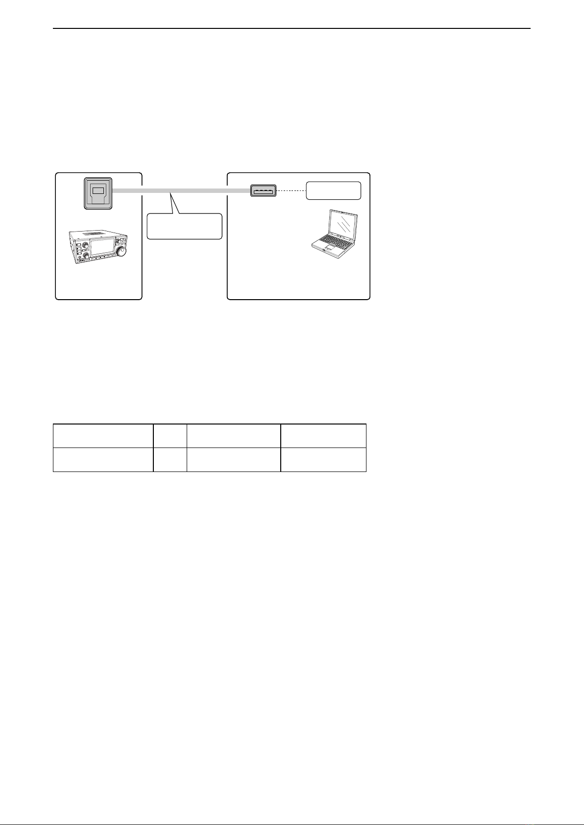
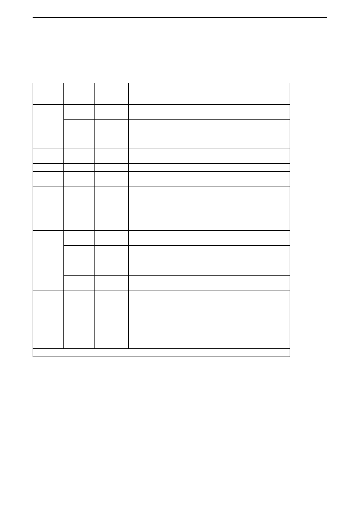
■Usable control commands
DCommand description
Command
Number
Sub
command
Number
Data Command Function
07 C2 00/01 Send/read the dualwatch setting
(00=OFF, 01=ON)
D2 00/01 Send/read the band selection
(00=Main, 01=Sub)
0F 00/01 Send/read the split setting
(00=Split OFF, 01=Split ON)
11 @9 00, 03 ~ 45 Send/read the Attenuator
(00=ATT OFF, 03=Minimum ~ 45=Maximum (3 dB step))
12 @9 See p.9 Send/read the antenna
14 02 @9 0000 ~ 0255 Send/read the RF Gain
(0000=Minimum, 0255=Maximum) (BCD value)
16* 02 @9 00/01/02 Send/read the PRE-AMP setting
(00=OFF, 01=P.AMP1 ON, 02=P.AMP2 ON)
4E @9 00/01 Set the DIGI-SEL function
(00=OFF, 01=ON)
65 @9 00/01 Send/read the IP+ function status
(00=OFF, 01=ON)
1A 0A* @9 00/01
Read the OVF indicator status
(00=OFF, 01=ON)
0B 00/01/02 Send/read the I/Q data output setting
(00=OFF, 01=Main band I/Q output, 02=Sub band I/Q output)
1C 00 00/01 Ttransceiver's status
(00=RX, 01=TX)
02 00/01 Transmit frequency monitor (XFC)
(00=OFF, 01=ON)
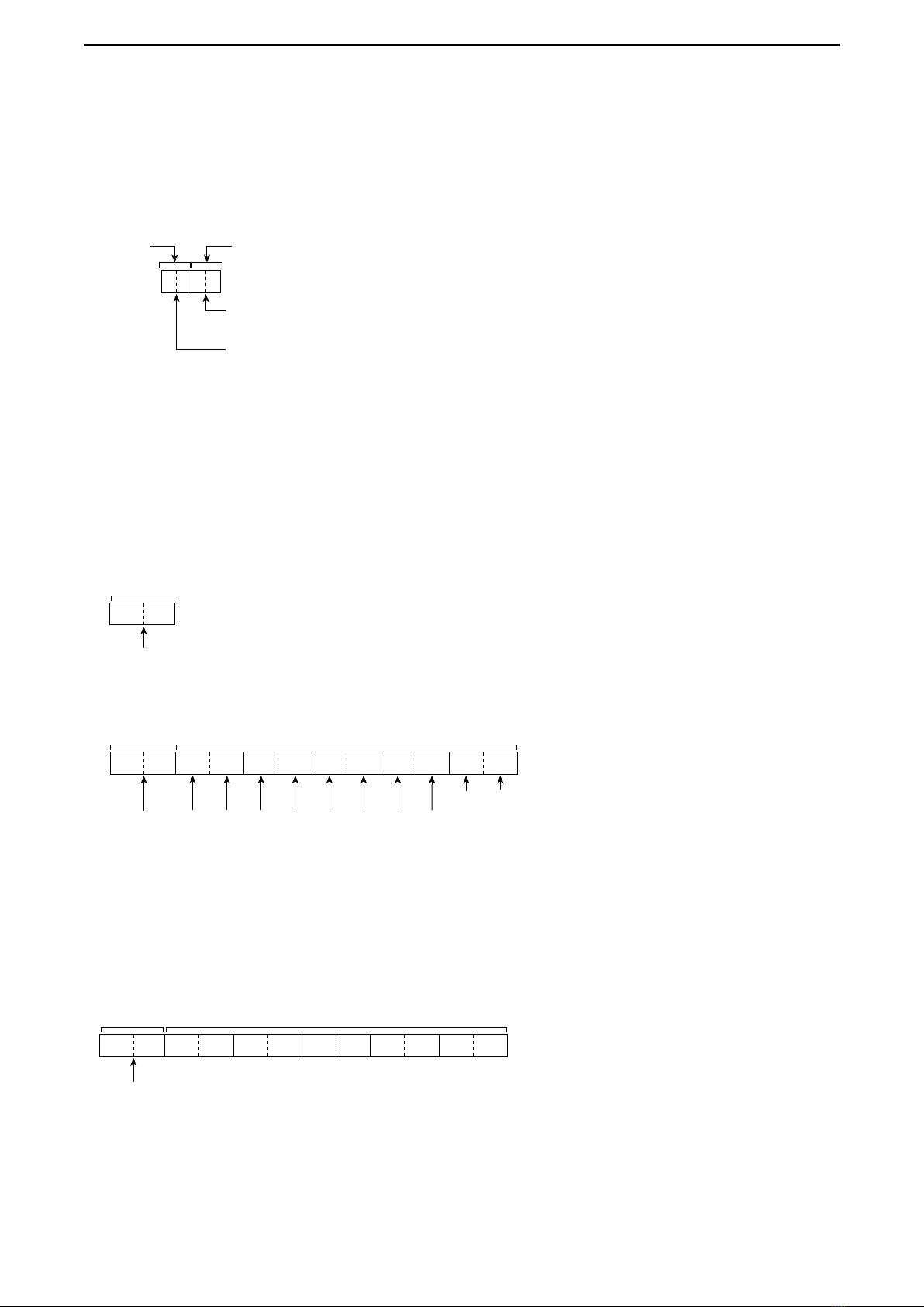
25 See p.9 Send/read the Main or Sub band frequency
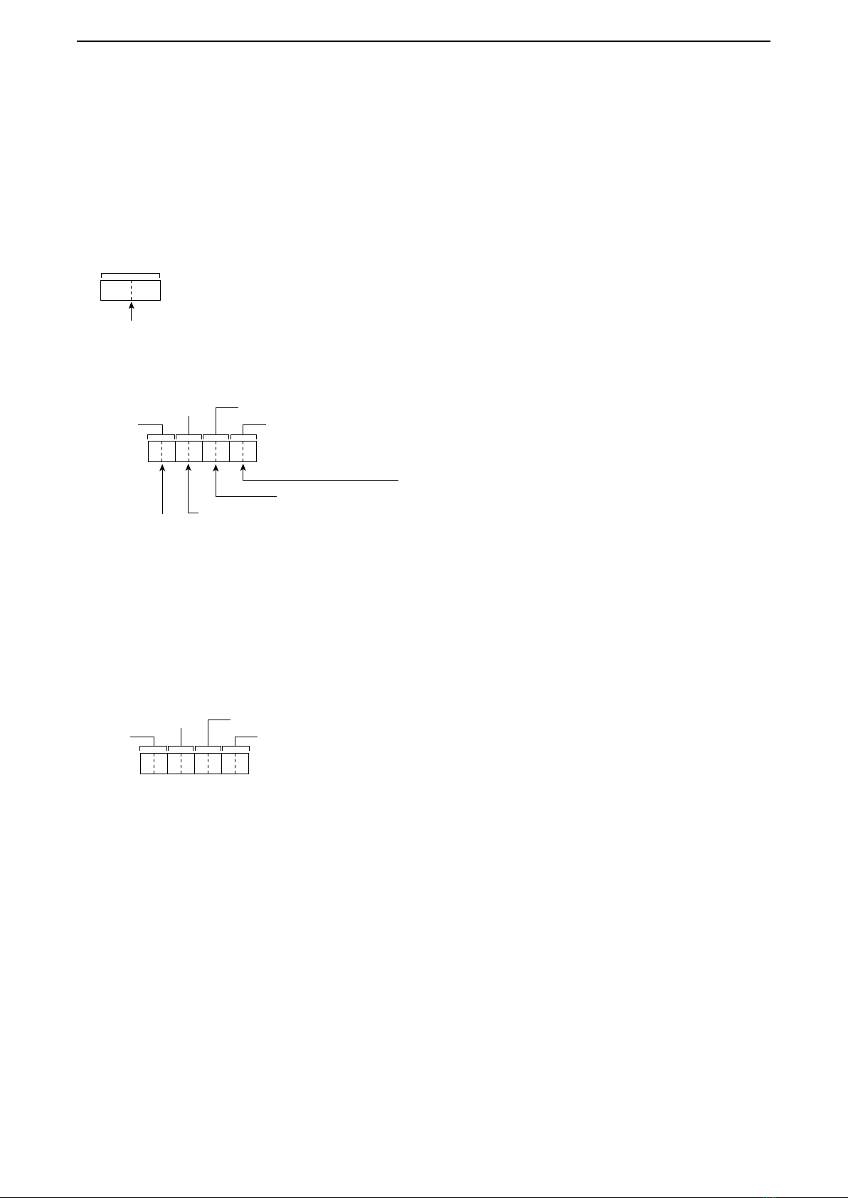
26 See p.10 Set the operating mode and lter setting
29 00 or 01
+
Supported
commends
See p.11
Regardless of active/inactive of the Main or Sub band, you can
directly specify the
Main or Sub band, and send/read the supported command
settings.
(00=Main band, 01=Sub band)
Commands other than listed above cannot be used with the [USB 2] port.
*(Asterisk) Read only data
@9 Regardless of active/inactive the Main or Sub band, you can directly specify the Main or Sub band, and send/read the
supported command settings. See page 11 for details.
I/Q SIGNAL