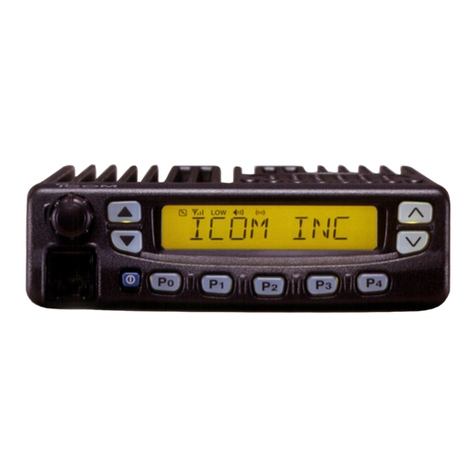
Icom iF4029SDR User manual

INSTRUCTION MANUAL
UHF TRANSCEIVER
iF4029SDR

i
RDANGER! Use and charge only specified Icom battery
packs with Icom radios or Icom chargers. Only Icom battery
packs are tested and approved for use with Icom radios or
charged with Icom chargers. Using third-party or counterfeit
battery packs or chargers may cause smoke, fire, or cause
the battery to burst.
RWARNING! NEVER hold the radio so that the
antenna is very close to, or touching exposed parts of the
body, especially the face or eyes, while transmitting.The radio
will perform best if the microphone is 5 to 10 cm away from
the lips and the radio is vertical.
RWARNING! NEVER operate the radio with a
headset or other audio accessories at high volume levels.
The continuous high volume operation may cause a ringing
in your ears. If you experience the ringing, reduce the volume
level or discontinue use.
RWARNING! NEVER operate the radio while driving
a vehicle. Safe driving requires your full attention—anything
less may result in an accident.
CAUTION: MAKE SURE the flexible antenna and
battery pack are securely attached to the radio, and that
the antenna and battery pack are dry before attachment.
Exposing the inside of the radio to water will result in serious
damage to the radio.
IMPORTANT
READ ALL INSTRUCTIONS carefully and com-
pletely before using the transceiver.
SAVE THIS INSTRUCTION MANUAL — This
instruction manual contains important operating instructions
for the IC-F4029SDR UHF TRANSCEIVER.
EXPLICIT DEFINITIONS
WORD DEFINITION
RDANGER! Personal death, serious injury or an explo-
sion may occur.
RWARNING! Personal injury, fire hazard or electric
shock may occur.
CAUTION Equipment damage may occur.
NOTE
If disregarded, inconvenience only. No risk
of personal injury, fire or electric shock.
Icom, Icom Inc. and the Icom logo are registered trademarks of Icom Incor-
porated (Japan) in Japan, the United States, the United Kingdom, Germany,
France, Spain, Russia and/or other countries.
All other products or brands are registered trademarks or trademarks of their
respective holders.
PRECAUTIONS

ii
1
2
3
4
5
6
7
8
9
10
11
12
13
14
15
16
DO NOT operate the radio near unshielded electrical
blasting caps.
DO NOT push [PTT] when you do not actually intend to
transmit.
DO NOT operate or place the radio in direct sunlight or in
areas with temperatures below –25°C or above +55°C.
DO NOT modify the radio. The specifications may change
and then not comply with the requirements of a corresponded
regulation. The radio warranty does not cover any problems
caused by unauthorized modification.
DO NOT use harsh solvents such as benzine or alcohol
when cleaning, as they will damage the radio surfaces.
KEEP the transceiver from the heavy rain, and Never im-
merse it in the water. The transceiver construction is water
resistant, not waterproof.
BE CAREFUL!The radio will become hot when operating
it continuously for long periods of time.
Even when the radio power is OFF, a slight current still flows
in the circuits. Remove the battery pack or batteries from
the radio when not using it for a long time. Otherwise, the
installed battery pack or batteries will become exhausted,
and will need to be recharged or replaced.
MAKE SURE to turn OFF the radio power before connecting
or disconnecting the supplied/optional accessory.
PRECAUTIONS

iii
VOICE CODING TECHNOLOGY
COUNTRY CODE LIST
• ISO 3166-1
Country Codes Country Codes
1
2
3
4
5
6
7
8
9
10
11
12
13
14
15
16
17
Austria
Belgium
Bulgaria
Croatia
Czech Republic
Cyprus
Denmark
Estonia
Finland
France
Germany
Greece
Hungary
Iceland
Ireland
Italy
Latvia
AT
BE
BG
HR
CZ
CY
DK
EE
FI
FR
DE
GR
HU
IS
IE
IT
LV
18
19
20
21
22
23
24
25
26
27
28
29
30
31
32
33
Liechtenstein
Lithuania
Luxembourg
Malta
Netherlands
Norway
Poland
Portugal
Romania
Slovakia
Slovenia
Spain
Sweden
Switzerland
Turkey
United Kingdom
LI
LT
LU
MT
NL
NO
PL
PT
RO
SK
SI
ES
SE
CH
TR
GB
The AMBE+2™ voice coding Technology embodied in this
product is protected by intellectual property rights including
patent rights, copyrights and trade secrets of Digital Voice
Systems, Inc. This voice coding Technology is licensed solely
for use within this Communications Equipment. The user of
this Technology is explicitly prohibited from attempting to ex-
tract, remove, decompile, reverse engineer, or disassemble
the Object Code, or in any other way convert the Object Code
into a human-readable form. U.S. Patent Nos.
#5,870,405, #5,826,222, #5,754,974, #5,701,390,
#5,715,365, #5,649,050, #5,630,011, #5,581,656, #5,517,511,
#5,491,772, #5,247,579, #5,226,084 and #5,195,166.

iv
1
2
3
4
5
6
7
8
9
10
11
12
13
14
15
16
TABLE OF CONTENTS
IMPORTANT...................................................................................... i
EXPLICIT DEFINITIONS................................................................... i
PRECAUTIONS................................................................................ ii
VOICE CODING TECHNOLOGY .................................................... iii
COUNTRY CODE LIST ................................................................... iii
TABLE OF CONTENTS................................................................... iv
1 ACCESSORIES ......................................................................1–2
n Supplied accessories...............................................................1
n Accessory attachments ...........................................................1
2 PANEL DESCRIPTION ...........................................................3–8
n Front panel...............................................................................3
n Function display.......................................................................5
n Programmable function keys ...................................................6
3 BASIC OPERATION .............................................................9–11
n Receiving and transmitting ......................................................9
n Lock function..........................................................................10
n Monitor function .....................................................................10
n All channel mode and Select channel mode..........................10
n Select channel setting............................................................11
n “My Name” function................................................................11
n Battery type selection ............................................................11
4 SCAN OPERATION ............................................................12–13
n Scan types.............................................................................12
n Scan list setting......................................................................12
n Starting a scan.......................................................................13
5 RINGER FUNCTION (Analog mode operation only).................14–15
n Smart-Ring operation ............................................................14
n Call-Ring operation................................................................15
n Auto channel function ............................................................15
6
TONE SQUELCH OPERATION (Analog mode operation only)
..16–18
n Operation...............................................................................16
n Tone scan operation...............................................................18
7 DIGITAL OPERATION ........................................................ 19–24
n Transmitting a call ..................................................................19
n Receiving a call......................................................................20
n Ringer operation ....................................................................20
n Break-in request call..............................................................21
n Status message.....................................................................23
n Digital mode indication...........................................................24
8 SET MODE..........................................................................25–28
n Set mode programming .........................................................25
n Set mode items......................................................................26
9 BATTERY CHARGING .......................................................29–33
n Caution ..................................................................................29
n Battery chargers ....................................................................31
10 BATTERY CASE .......................................................................34
n Optional battery case (BP-240) .............................................34
11 SWIVEL BELT CLIP ...........................................................35–36
n MB-93 contents......................................................................35
n To attach ................................................................................35
n To detach ...............................................................................36
12 SPECIFICATIONS...............................................................37–39
n Specifications.........................................................................37
n Channel frequency lists .........................................................38
13 OPTIONS ............................................................................40–41
1
1ACCESSORIES
nSupplied accessories
Battery pack
Belt clip Jack cover
(with screws)
Power adapter*
(for the battery charger)
Battery charger
*A different type is supplied,
depending on the version.
nAccessory attachments
ï Battery pack
To attach the battery pack:
Slide the battery pack in the direction of the arrow (q), then
lock it with the battery release button.
• Slide the battery pack until the battery release button makes a ‘click’
sound.
To remove the battery pack:
Slide the battery release button in the direction of the arrow
(w) as shown below. The battery pack is then released, and
you can remove it.
NEVER remove or attach the battery pack when the
transceiver is wet or soiled. This may result water or dust
getting into the transceiver/battery pack and may result in
the transceiver being damaged.
q
w
Battery release button
Battery pack
NOTE: Keep the battery pack terminals clean. It’s a good
idea to occasionally clean them.

ï Belt clip
To attach the belt clip:
qRemove the battery pack if it is attached.
wSlide the belt clip in the direction of the arrow until the belt
clip is locked and makes a ‘click’ sound.
To detach the belt clip:
qRemove the battery pack if it is attached.
wPinch the clip (q), and slide the belt clip in the direction of
the arrow (w).
q
w
ï Jack cover
To attach the jack cover:
qInsert the jack cover into
the [MIC/SP] jack.
wTighten the screws.
•
Use the supplied screws only.
To detach the jack cover:
eUnscrew the screws using
a phillips screwdriver.
rDetach the jack cover for
the optional speaker-mi-
crophone or headset con-
nection.
[MIC/SP] jack
Jack cover
e
e
w
qr
CAUTION: Attach the jack cover when the optional
accessory is not used. Otherwise the terminals of the [MIC/
SP] jack may be shorted by metal object, etc., and this
could damage the transceiver.
2
1
ACCESSORIES
1
2
3
4
5
6
7
8
9
10
11
12
13
14
15
16

3
2PANEL DESCRIPTION
nFront panel
q
e
w
r
tu
i
o
y
Speaker
Microphone
Antenna
qTOP SWITCH (Default: LOCK)
Push and hold for 1 sec. to toggle the key lock function ON
and OFF.
• Desired function can be programmed by your dealer. (p. 6)
wSIDE 1 KEY (Default: MONITOR/CODE)
Analog mode operation: [MONI]
Mute and release the CTCSS (DTCS) squelch mute. Open
any squelch/deactivate any mutes after pushing and hold-
ing this key.
Digital mode operation: [CODE]
Push to display the programmed Common ID, then push
[Side2] (CH Up)/[Side3] (CH Down) to select the desired
ID.
• Desired function can be programmed by your dealer. (p. 6)
ePTT SWITCH [PTT]
Push and hold to transmit; release to receive.
rSIDE 2 KEY (Default: CH UP)
tSIDE 3 KEY (Default: CH DOWN)
➥Push to select an operating channel.
➥Push to select the desired CTCSS/DTCS tone after
pushing [CODE]. (During Analog channel operation)
➥Push to select the desired Common ID after pushing
[Side1] (CODE). (During Digital channel operation)
➥Push to select a TX status message after pushing
(SELECT). (During Digital channel operation)
➥Push to select the set mode contents in user set mode.
➥Push to select a scan group after pushing and holding
[Scan A Start/Stop]/[Scan B Start/Stop].
• Desired functions can be programmed independently by your
dealer. (p. 6)

4
2
PANEL DESCRIPTION
2
yDEALER-PROGRAMMABLE KEYS ( ///)
The following functions are assigned to each program-
mable key as the default.
Analog mode operation:
; S-Ring/Ringer : Push to send a Smart-Ring call.
Push and hold to send a Call-Ring.
; Zone : Push this key, then change the zone
up or down using [Side2] (CH Up)/
[Side3] (CH Down).
; A/S : Push to toggle All and Select channel
mode.
; Null : No function is assigned.
Digital mode operation:
; Call : Push to transmit the programmed
Common ID code on the selected
channel to make a group call.
; Zone : Push this key, then change the zone
up or down using [Side2] (CH Up)/
[Side3] (CH Down).
; Select : Push to display the TX status mes-
sage.
; Clear : Push to finish the conversation (send-
ing a clear down signal) and return to
standby condition.
• Desired functions can be programmed independently by your
dealer. (p. 6)
uFUNCTION DISPLAY (p. 5)
Displays a variety of information, such as an operating
channel number/name, CTCSS frequency, the status mes-
sage, etc.
iEXTERNAL MICROPHONE/SPEAKER JACK
Connect the optional speaker-microphone or headset.
NOTE: Connect or disconnect the optional equipment
after the transceiver is turned OFF.
Jack cover
NOTE: Attach the jack
cover when the optional
accessory is not used.
(See page 2 for details)
oVOLUME CONTROL [VOL]
Rotate to turn the power ON/OFF and adjusts the audio
level.
NOTE: The default setting is used in this instruction man-
ual for description.

5
2PANEL DESCRIPTION
nFunction display
q oiuytrew
!0
!1
qTRANSMIT INDICATOR
Appears while transmitting.
wBUSY INDICATOR
Appears while the channel is busy.
eSIGNAL STRENGTH INDICATOR
Indicates relative signal strength level.
rDRY CELL INDICATOR
Appears during the optional battery case operation. (p. 11)
tAUDIBLE INDICATOR
➥ Appears when the channel is in the ‘audible’ (unmute)
condition. (Analog mode operation only)
➥ Appears when the matched CTCSS or DTCS code
number is received. (Analog mode operation only)
➥ Appears during communication. (Digital mode operation
only)
yRINGER INDICATOR
Appears while sending a Smart-Ring call or Call-Ring.
(Analog mode operation only)
uBELL INDICATOR
➥Blinks when the matched Smart-Ring call is received.
(Analog mode operation only)
➥Blinks when the Ringer call is received. (Digital mode
operation only)
iCALL CODE INDICATOR
➥Appears during in the CTCSS/DTCS tone selection
mode. (Analog mode operation only)
➥Appears during in the Common ID selection mode.
(Digital mode operation only)
oKEY LOCK INDICATOR
Appears during the key lock function is ON.
!0 BATTERY INDICATOR
Appears or blinks when the battery power decreases to a
specified level.
!1 ALPHANUMERIC DISPLAY
Displays an operating channel number/name, CTCSS fre-
quency, the status message, etc.

6
2
PANEL DESCRIPTION
nProgrammable function keys
The desired key function can be assigned to the programma-
ble function keys ( , , or ) in following way.
qSelect the desired operating mode (Analog or Digital), then
turn power OFF.
wWhile pushing and holding [Side3] (CH Down) and the de-
sired key ( , , or ) to be assigned, rotate [VOL]
to turn power ON.
• The selected function name is displayed for a moment.
• The desired key function is assigned to the pushed key ( ,
, or ) in the selected operating mode.
eTurn power OFF.
rRepeat steps wand euntil the desired key function is
selected.
Consult your Icom dealer or system operator for details con-
cerning [Top], [Side1], [Side2] and [Side3] programming.
ï Usable functions
CH UP AND DOWN KEYS
➥Push to select an operating channel.
➥Push to select the desired CTCSS/DTCS tone after push-
ing [CODE]. (During Analog mode operation)
➥Push to select the desired Common ID after pushing
[CODE]. (During Digital mode operation)
➥Push to select a TX status message after pushing
[SELECT]. (During Digital channel operation)
➥Push to change the value or condition in user set mode.
➥Push to select the desired scan list from “SCAN 1” or
“ZONE” after pushing and holding [Scan A Start/Stop]/
[Scan B Start/Stop].
ZONE KEY
Push this key, then change the zone up or down using [CH
Up]/[CH Down].
What is “zone”?— The desired channels are assigned
into a zone according to the intended use for grouping. For
example, ‘Staff A’ and ‘Staff B’ are assigned into a “Busi-
ness” zone, and ‘John’ and ‘Cindy’ are assigned into a “Pri-
vate” zone.
2
*Information
Up to two desired functions, one each for Analog and Digital
operation mode, can be assigned to [Top], [Side1], [Side2],
[Side3], , , and keys.
The default setting is used in this instruction manual, for
description.

7
2PANEL DESCRIPTION
SCAN A START/STOP KEY
➥Push to start and cancel scanning operation.
In case of transmission during scan, scanning will be can-
celled.
➥Push and hold this key for 1 sec. to indicate the scan list,
then select the desired scan list from “SCAN 1” or “ZONE”
using [CH Up]/[CH Down].
SCAN B START/STOP KEY
➥Push to start and cancel scanning operation.
In case of transmission during scan, scanning will be
paused. Then resumes after a specified time period has
passed after the transmission is finished.
➥Push and hold this key for 1 sec. to indicate the scan list,
then select the desired scan list from “SCAN 1” or “ZONE”
using [CH Up]/[CH Down].
MONI KEY (Analog mode operation only)
Mute and release the CTCSS (DTCS) squelch mute. Open
any squelches/deactivate any mutes after pushing and hold-
ing this key.
LOCK KEY
➥Push and hold for 1 sec. to electronically lock all program-
mable keys except the following:
[Call]*1, [Moni]*2and [PTT].
*
1Digital mode operation only.
*
2Analog mode operation only.
➥Push and hold for 1 sec. again to turn the lock function
OFF.
USER SET MODE KEY
➥Push and hold to enter user set mode.
• During user set mode, push this key to select an item, and
change the value or condition using push [CH Up]/[CH Down].
➥Push and hold this key again to exit user set mode.
S-RING/RINGER KEY (Analog mode operation only)
➥Push to send a Smart-Ring call.
➥Push and hold to send a Call-Ring.
CODE KEY
Analog mode operation:
➥Push to enter CTCSS/DTCS tone selection mode, then
push [CH Up]/[CH Down] to select the desired CTCSS/
DTCS tone.
➥Push and hold to start the tone scan.
Digital mode operation:
Push to display the programmed Common ID, then push [CH
Up]/[CH Down] to select the desired ID.
MY NAME KEY (Analog mode operation only)
Push to display the pre-programmed “My Name” text.
AUTO CH KEY (Analog mode operation only)
Push to start searching for a clear channel.
A/S KEY
Push to toggle All and Select channel mode.
When All channel mode is selected, inhibited channels will
be selectable.

8
2
PANEL DESCRIPTION
CALL KEY (Digital mode operation only)
Push to transmit the programmed Common ID on the select-
ed channel to make a group call.
CLEAR KEY (Digital mode operation only)
Push to finish the conversation (sending a clear down signal)
and return to standby condition.
SELECT KEY (Digital mode operation only)
Push to display the status message, then push [CH Up]/[CH
Down] to select the desired status message.
The first 8-digit of status message is displayed during selec-
tion.
BREAK KEY (Digital mode operation only)
Push to transmit a break-in request call.
2

9
3BASIC OPERATION
nReceiving and transmitting
Prior to using the transceiver for the first time, the battery
pack must be fully charged for optimum life and operation.
(P. 29)
Receiving:
qRotate [VOL] clockwise to turn the power ON.
wPush [Side2] (CH Up) or [Side3] (CH Down) to select the
desired operating channel. (pgs. 38, 39)
• Push (Zone) then push [Side2] (CH Up) or [Side3] (CH Down)
to select the desired zone, if required.
• Setting the CTCSS/DTCS tone code if required. (pgs. 16, 17)
eListen for a transmission and adjust [VOL] to a comfortable
listening level.
• “ ” appears when the matched CTCSS or DTCS code number
is received.
• When no transmission is heard, push and hold [Side1] (Moni)
while adjusting [VOL]. (Analog mode operation only)
The transceiver is now set to receive desired calls on the se-
lected channel.
Transmitting:
Wait for the channel to become clear to avoid interference.
qWhile pushing and holding [PTT], speak into the micro-
phone at a normal voice level.
• “ ” and “ ” appears.
wRelease [PTT] to return to receive.
NOTE: To maximize the readability of your signal;
1. Pause briefly after pushing [PTT].
2. Hold the microphone 5 to 10 cm (2 to 4 inches) from
your mouth, then speak into the microphone at a normal
voice level.
ï Transmitting notes
• Transmit inhibit function
The transceiver has several inhibit functions which restrict
transmission under the following conditions:
- The channel is in mute condition (‘Inaudible’ condition;
“” does not appear.)
- The channel is busy.
- Un-matched (or matched) CTCSS is received.
(Depending on the pre-setting.)
- The selected channel is a ‘receive only’ channel.
- Transmission is inhibited only while receiving a signal with
the signal strength is stronger than "RSSI L0 (-105 dBm)"
level including a matched Common ID.*
*Digital mode operation only.
• Time-out timer
After continuous transmission for the pre-programmed time
period, the time-out timer is activated, causing the transceiver
to stop transmitting.
• Penalty timer
Once the time-out timer is activated, transmission is further
inhibited for a period determined by the penalty timer.

10
3
BASIC OPERATION
3
nLock function
The lock function provides accidental channel changes and
function access.
➥Push [Top] (LOCK) for 1 sec. to toggle the lock function
ON and OFF.
• (Call)*1, [Side1] (Moni)*2and [PTT] are available while the
lock function is ON.
• “ ” appears.
*
1Digital mode operation only.
*
2Analog mode operation only.
Appears
nMonitor function
This function is used to listen to weak signals or to open the
tone squelch manually. (Analog mode operation only)
➥Push and hold [Side1] (Moni) to monitor the operating
channel.
• “ ” appears.
Appears
nAll channel mode and
Select channel mode
The transceiver has 2 indication mode— All channel mode
and Select channel mode.
Select channel mode provides easy, fast channel selection
and speeds up the scan interval. Non select channels are not
displayed while in Select channel mode.
➥Push [A/S] to toggle All channel mode and Select channel
mode.
• “ALL” or “SELECT” is displayed for about 1 sec. when All or
Select channel mode is selected. After indication, return to the
standby condition.
All channel mode
Select channel mode

11
3BASIC OPERATION
nSelect channel setting
For Select channel mode operation, add the desired channels
as ‘Select channels’ or clear the unwanted channels (Non-se-
lect channels).
qPush [A/S] to select All channel mode.
wPush [Side2] (CH Up) or [Side3] (CH Down) to select the
desired channel.
e Push [A/S] for 1 sec. to toggle the channel between ‘Select
channel’ and ‘Non-select channel.’
Appears
Select channel
Non-select channel
n“My Name” function
The transceiver displays up to 8-character its name (or a
comment) when turning power ON and when the [My Name]
is pushed. (Analog mode operation only)
Ask your dealer for name programming details.
➥While pushing and holding [My Name], the pre-pro-
grammed name or a comment is displayed.
Pre-programmed
My name
nBattery type selection
The battery type must be selected according to the attaching
battery type when turning the transceiver ON.
Ask your dealer for details.
qTurn the power OFF.
wWhile pushing and holding [Top] and [PTT], rotate [VOL] to
toggle the attaching battery type.
• After the display appears, release [Top] and [PTT].
• “DRY BATT” is displayed for about 3 sec. then “L” appears when
the battery case operation is selected. In this case, the transmit
output power is low.
• “LI-ION” is displayed for about 3 sec. when the Lithium-ion bat-
tery operation is selected.

12
4
SCAN OPERATION
3
4
nScan types
Scanning is an efficient way to locate signals quickly over all
channel.
Setting ‘Select channels’ (p. 11) and using Select channel
mode (p. 10) speeds up the scanning interval.
In addition, repeatedly scanning all zone channels or selected
zone channels can be selected.
Repeatedly scans select
channels only, in se-
quence.
Non select
channel
ch 16
ch 1 ch 2 ch 3
ch 4
ch 5
ch 6ch 15
Repeatedly scans all
channels including Non
select channels in se-
quence.
Non select
channel
ch 16
ch 1 ch 2 ch 3
Non select
channel
ch 5
ch 6ch 15
ch 4
SCAN in Select channel mode
SCAN in All channel mode
Non select
channel
nScan list setting
2 scanning lists (“SCAN 1” and “ZONE”) are available for wide
variety and flexible scanning operation.
Repeatedly scans all
zone channels.
ch 16
ch 1 ch 2 ch 3
ch 4
ch 5
ch 6ch 15
Repeatedly scans the
zone that includes the
scan start channel.
ch 1
Zone 1
Zone 1
Zone 2
ch 2 ch 16
ch 2
ch 16Zone 3
ch 1
SCAN1
ZONE
Zone 4
Scan start channel
qPush [Scan A] or [Scan B] for 1 sec. to indicate the scan list,
then select the desired scan list from “SCAN 1” or “ZONE”
using [Side2] (CH Up)/[Side3] (CH Down).
wPush [Scan A] or [Scan B] to return to the standby condi-
tion.

13
4SCAN OPERATION
nStarting a scan
To speed up the scanning interval, set the desired channels
as ‘Select channels’ and set Select channel mode in advance.
(pgs. 10, 11)
qPush [Scan A] or [Scan B] to start scanning.
wWhen a signal is received, scan pauses and resumes ac-
cording to the included CTCSS frequency or DTCS code.
(pgs. 16, 17)
• When the code is matched, scan resumes 3 sec. after the signal
disappears.
• When the code is not matched, scan resumes immediately.
ePush [Scan A] or [Scan B] to stop scanning.
BlinksAppears
Blinks
When a signal is received.
Starting Scan 1 .

14
5
RINGER FUNCTION (Analog mode operation only)
4
5
nSmart-Ring operation
The ring function has an answer back feature. This allows you
to confirm whether or not a call has reached to the member
of your group even if the operator is temporarily away from
the transceiver.
qSet the same operating channel and CTCSS tone code for
all of your group transceivers.
wPush (S-Ring/Ringer) to send the Smart-Ring call.
• “ ” and “ ” appears.
• When a member of your group station answers your call, the
transceiver emits beep tones for every 10 sec. and “ ” blinks.
• Push [Side1] (MONI) to cancel the Ringer beep and “ ” blinks.
• When no answer comes back, the transceiver emits short failure
beep tones.
AppearsAppears
While transmitting
ePush [PTT] to answer the call and to stop the beeps and
blinking.
NOTE: This function is available only when the called
station has use the same CTCSS tone code and the
same operating channels as you.
(S-Ring/Ringer)
Piro Piro
Answer back (automatic)
Piro Piro
Communication
Push

15
5RINGER FUNCTION (Analog mode operation only)
nCall-Ring operation
q Set the same operating channel and CTCSS tone code for
all of your group transceivers.
w Push and hold (S-Ring/Ringer) to send the pre-se-
lected ring tone to your group members.
• “ ” and “ ” appears.
• The ring tone* is emitted while (S-Ring/Ringer) is pushed
and held.
• The same ring tone comes from your group station’s speaker.
AppearsAppears
While transmitting
* The Call-Ring emission type can be selected in Set mode.
(p. 27)
nAuto channel function
The auto channel function automatically searches a clear
channel during scan when (S-Ring/Ringer) is pushed.
Then, the ringer tone is transmitted for a specified period in
the founded clear channel. Another station during scanning
may answer the call in the clear channel if it receives the
ringer signal.
q Push [Auto Ch] to start scan.
• The selected scan type and scan list are available. (pgs. 10, 12)
wTo call a waiting station, push (S-Ring/Ringer) for 1 sec.
to transmit a ringer tone.
• The auto channel function automatically searches a clear chan-
nel. After a clear channel found, a ringer tone is transmitted.
• To call a waiting station by voice, push [PTT] until beep tones
sound (for longer than the ringer time), then speak into the mi-
crophone.
eThe auto channel function restarts 30 sec. later after a
busy signal disappears and in which no operation is per-
formed while the auto channel function is in use.
rPush [Auto Ch] to cancel the function.
This manual suits for next models
1
Table of contents
Other Icom Transceiver manuals

Icom
Icom IC-F80DT Installation and operating instructions

Icom
Icom IC-1200A User manual

Icom
Icom IC-2GA User manual

Icom
Icom IC-V82 User manual

Icom
Icom IC-F5121D User manual

Icom
Icom IC-E90 User manual

Icom
Icom IC-F4261DT User manual

Icom
Icom IC-F1610 User manual

Icom
Icom IC-281A User manual

Icom
Icom IF1721/D User manual