Icom IC-440 User manual

INSTRUCTION MANUAL
i440
UHF CB TRANSCEIVER
IC-440-1.inddaIC-440-1.indda 2008/06/2515:59:222008/06/2515:59:22

i
IMPORTANT
READ ALL INSTRUCTIONS carefully and com-
pletely before using the transceiver.
SAVE THIS INSTRUCTION MANUAL — This
instruction manual contains important operating instructions
for the IC-440 UHF CB TRANSCEIVER.
EXPLICIT DEFINITIONS
OPERATING NOTES
BUSY CHANNEL
Always listen to a channel (or observe the channel busy indicator on the
display) to ensure that the channel is not already in use before transmitting.
CALLING CHANNELS (CB-11,CB-40)
In Australia channel 11 is the customary calling channel for establishing
communication and channel 40 is the customary road vehicle channel.
EMERGENCY CHANNELS (CB-05, CB-R5, CB-35)
In Australia except in an emergency, a CB transmitter must not be oper-
ated on UHF emergency channels 5 & 35.
NOTE: if the Radio is switched off while on an Emergency channel,
the Radio when switched on again, will be on the (software preset
channel) CB-11.
DATA CHANNELS (CB-22, CB-23)
No voice transmissions are permitted on data channels 22 and 23. (Note:
Voice operation is inhibited on channels 22 and 23).
REPEATER CHANNELS (CB-R1 to CB-R8)
UHF CB repeaters provide greater range through a base station that re-
transmits the signal. Repeaters operate utilizing two channels (repeater
input/ repeater output channels). It is important to avoid operation on
locally used repeater input channels (which will be in the range channels
31 to 38) or locally used repeater receiving channels (which will be in
the range channels 1 to 8), unless long distance communication via the
repeater facility is specifically required. (Please also see: Repeater Op-
eration, Repeater Search Scan).
CLASS LICENCE
The citizen band radio service is licensed in Australia by The ACMA Radio-
communications (Citizens Band Radio Stations) Class Licence and in New
Zealand by MED General User Radio Licence for Citizens Band Radio and
operation is subject to conditions contained in those licences.
Icom, Icom Inc. and the logo are registered trademarks of Icom
Incorporated (Japan) in the United States, the United Kingdom, Germany,
France, Spain, Russia and/or other countries.
WORD DEFINITION
RWARNING Personal injury, fire hazard or electric
shock may occur.
CAUTION Equipment damage may occur.
NOTE If disregarded, inconvenience only. No risk
of personal injury, fire or electric shock.
IC-440-1.inddiIC-440-1.inddi 2008/06/2515:59:272008/06/2515:59:27

ii
RWARNING! NEVER connect the transceiver to an AC
outlet. This may pose a fire hazard or result in an electric shock.
RWARNING! NEVER operate the transceiver while
driving a vehicle. Safe driving requires your full attention—
anything less may result in an accident.
NEVER connect the transceiver to a power source of
more than 27.6 V DC. This will damage the transceiver.
NEVER connect the transceiver to a power source using
reverse polarity. This will damage the transceiver.
NEVER cut the DC power cable between the DC plug and
fuse holder. If an incorrect connection is made after cutting,
the transceiver may be damaged.
NEVER expose the transceiver and microphone to rain,
snow or any liquids. The transceiver and microphone may be
damaged.
NEVER operate or touch the transceiver and microphone
with wet hands. This may result in an electric shock or damage
the transceiver and microphone.
NEVER place the transceiver where normal operation of the
vehicle may be hindered or where it could cause bodily injury.
DO NOT push the PTT when not actually desiring to transmit.
DO NOT allow children to play with any radio equipment
containing a transmitter.
DO NOT operate the transceiver for extended periods
without running the vehicle’s engine. The transceiver’s power
consumption may soon exhaust the vehicles battery.
DO NOT use or place the transceiver in direct sunlight or
in areas with temperatures below –10°C or above +60°C.
DO NOT set the transceiver in a place without adequate
ventilation. Heat dissipation may be affected, and the trans-
ceiver may be damaged.
DO NOT use the chemical agents such as benzine or alcohol
when cleaning, as they can damage the transceiver’s surfaces.
USE Icom microphones only (supplied or optional). Other
manufacturer’s microphones have different pin assignments
and may damage the transceiver if attached.
PRECAUTIONS
IC-440-1.inddiiIC-440-1.inddii 2008/06/2515:59:282008/06/2515:59:28

iii
TABLE OF CONTENTS
IMPORTANT··························································································· i
EXPLICIT DEFINITIONS········································································ i
OPERATING NOTES·············································································· i
PRECAUTIONS······················································································ ii
TABLE OF CONTENTS········································································· iii
1 ACCESSORIES AND CONNECTION ········································· 1–5
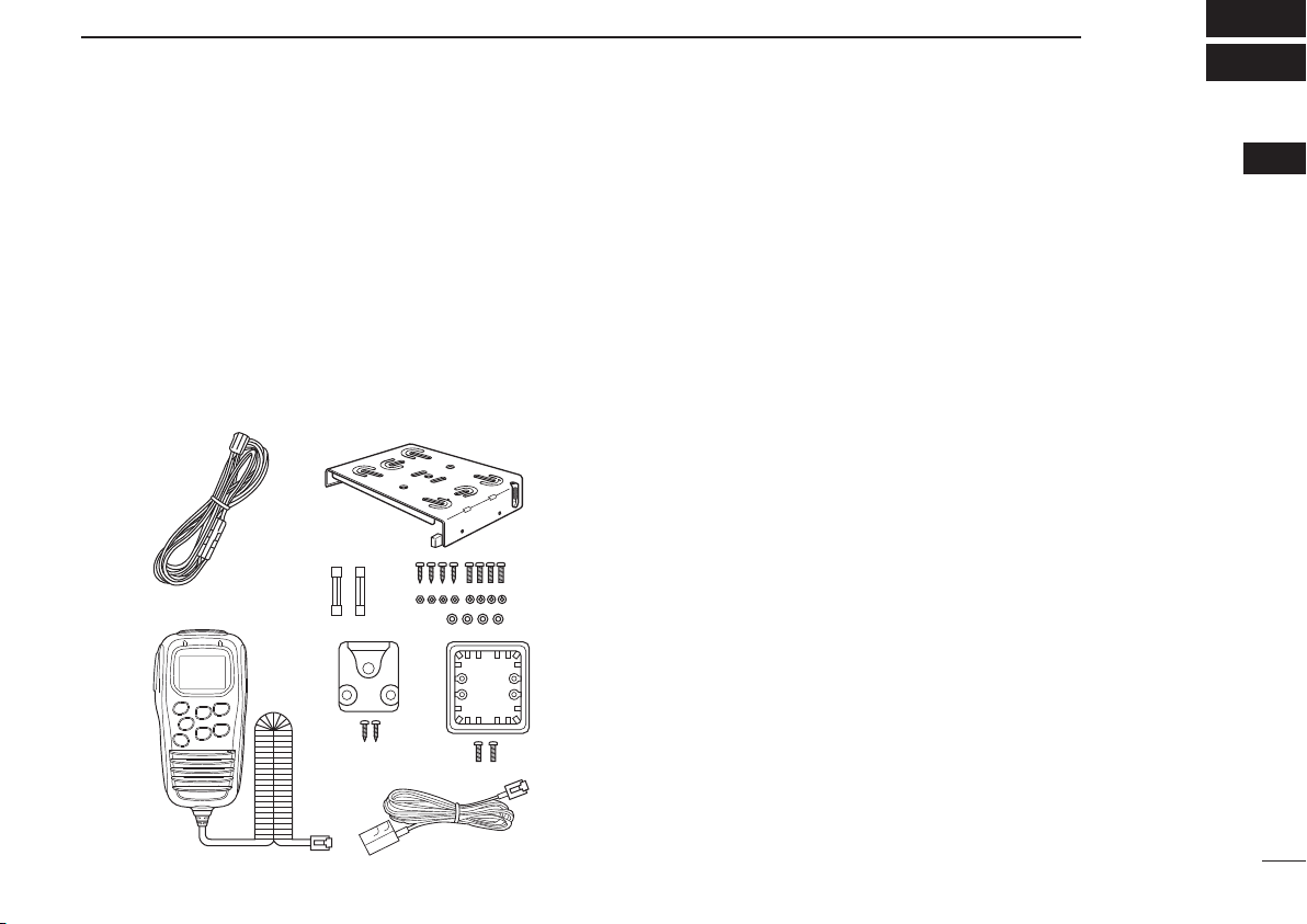
■Supplied accessories ··································································· 1
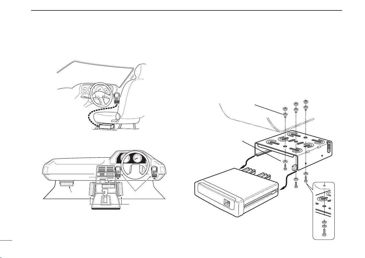
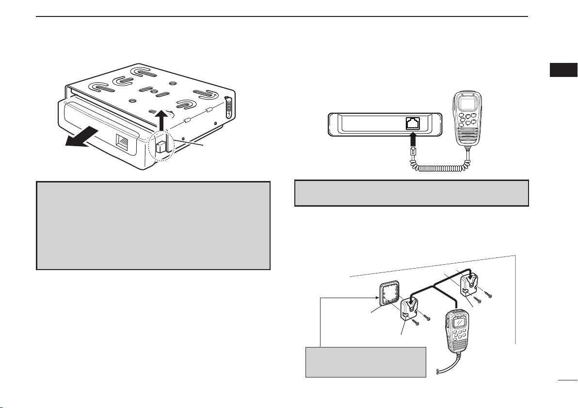
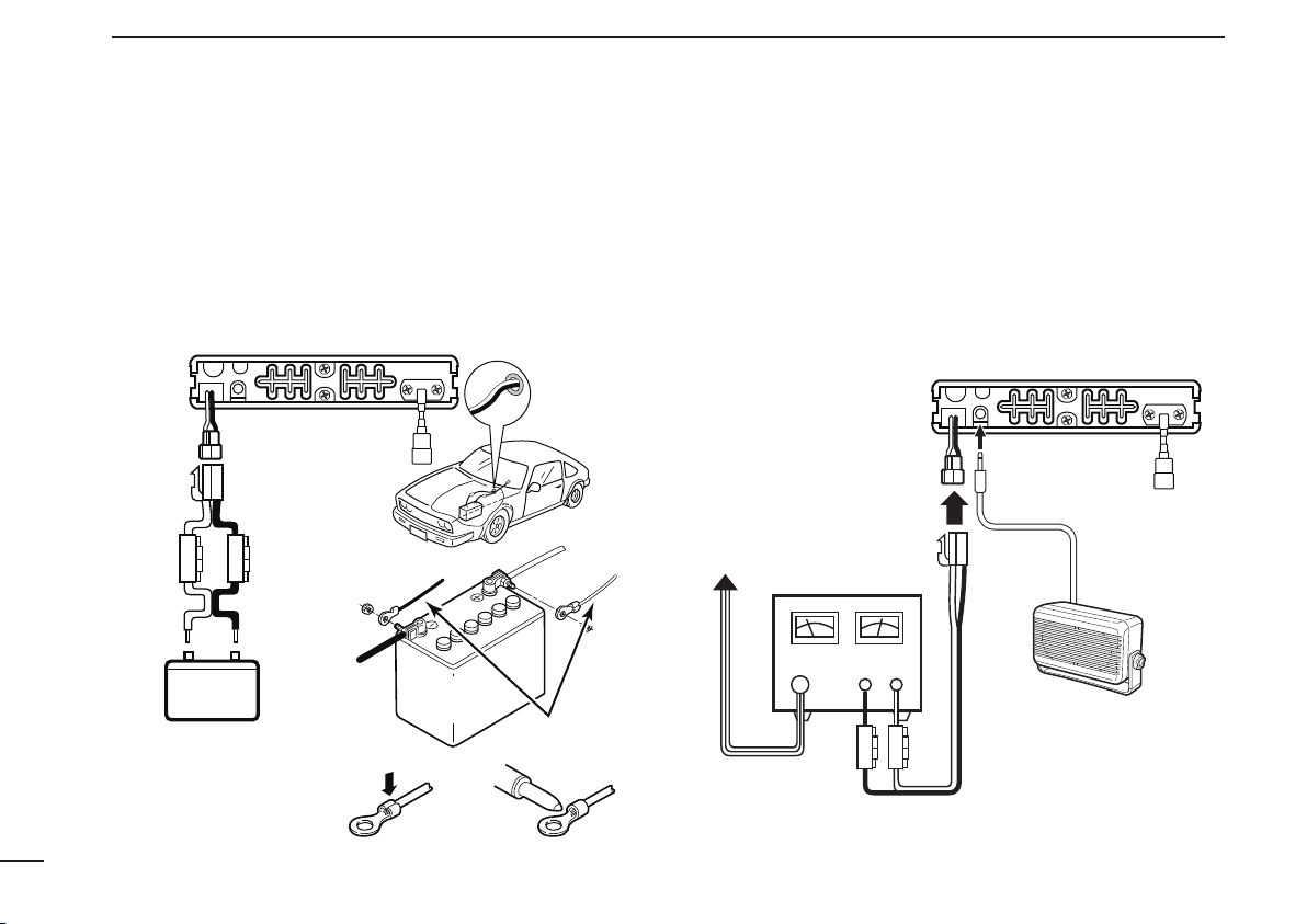
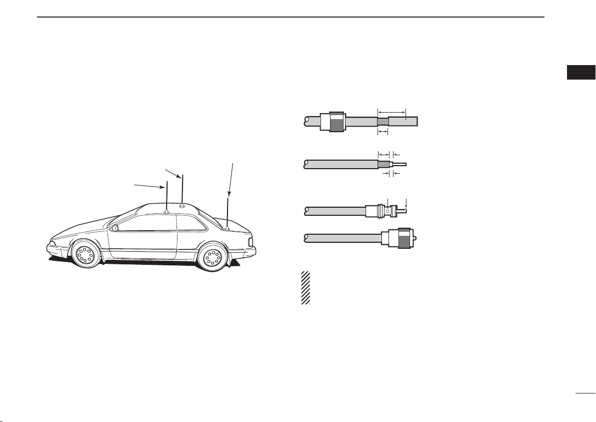
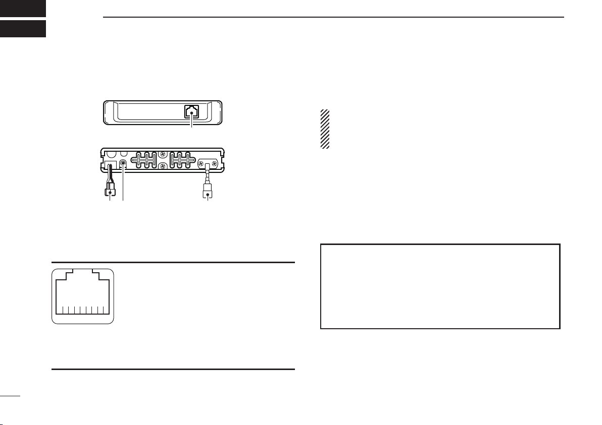
■Installation ···················································································· 1
2 PANEL DESCRIPTION······························································ 6–13
■IC-440 front and rear panels························································· 6
■HM-182 front and top panels························································ 7
■Function display·········································································· 10
■Programmable function keys ······················································ 12
3 BASIC OPERATION ································································ 14–19
■Turning power ON······································································· 14
■Volume selection········································································· 14
■Channel selection······································································· 14
■Receiving and transmitting ························································· 15
■Priority channel setting ······························································· 17
■Monitor function·········································································· 18
■Lock function ·············································································· 18
■Adjusting the squelch level ························································· 18
■Display backlighting ···································································· 19
■Set mode ···················································································· 19
4 REPEATER OPERATION ······························································ 20
■Repeater operation····································································· 20
■Accessing a repeater·································································· 20
5 SCAN OPERATION ································································· 21–25
■Scan types·················································································· 21
■Scanning preparation ································································· 22
■Open scan ·················································································· 23
■Group and priority scans ···························································· 24
■Repeater search scan ································································ 25
6 TONE SQUELCH OPERATION··············································· 26–28
■Tone squelch operation······························································· 26
■Pocket beep operation································································ 28
7 SELCALL OPERATION··························································· 29–33
■General······················································································· 29
■Calling operation········································································· 29
■When receiving a call ································································· 32
■Quiet mode operation································································· 33
■Stun function··············································································· 33
8 OTHER FUNCTIONS······························································· 34–39
■Smart-Ring and ATS (Automatic Transponder System)·············· 34
■RX frequency setting (for RX channels only) ····························· 35
■Wide/Narrow function ································································· 37
■PTT hold function ······································································· 38
■Data cloning················································································ 38
■All reset······················································································· 39
9 SET MODE ·············································································· 40–46
■Set mode ···················································································· 40
■SET mode items········································································· 41
10 MAINTENANCE······································································· 47–48
■Troubleshooting ·········································································· 47
■Fuse replacement······································································· 48
11 SPECIFICATIONS AND OPTIONS ········································· 49–50
■Specifications ············································································· 49
■Options ······················································································· 50
12 WARRANTY AND PRODUCT REGISTRATION ····················· 51–54
INDEX···························································································· 57–59
IC-440-1.inddiiiIC-440-1.inddiii 2008/06/2515:59:282008/06/2515:59:28

1
1
ACCESSORIES AND CONNECTION
1
■ Supplied accessories
qDC power cable (3 m) ····················································· 1
wMounting bracket····························································· 1
eMicrophone (HM-182) ····················································· 1
rFuses (FRG 5 A)····························································· 2
tMounting screws, nuts and washers ························· 1 set
yMicrophone hanger set ··················································· 1
uMicrophone hanger attachment plate ····························· 1
iMicrophone cable (2.5 m) ··············································· 1
■ Installation
ïLocation
Select a location which can support the weight of the trans-
ceiver and does not interfere with driving. We recommend
the locations shown in the diagram at p. 2.
NEVER place the transceiver or microphone where normal
operation of the vehicle may be hindered or where it could
cause bodily injury.
NEVER place the transceiver or microphone where air bag
deployment may be obstructed.
DO NOT place the transceiver or microphone where hot or
cold air blows directly onto it.
DO NOT place the transceiver or microphone in direct sun-
light.
qw
e
r
yu
i
t
IC-440-1.indd1IC-440-1.indd1 2008/06/2515:59:282008/06/2515:59:28

2
1ACCESSORIES AND CONNECTION
ïInstallation methods
<Sample 1: IC-440 is installed under a driver’s seat.>
<Sample 2: IC-440 is installed under a dash box, etc.>
DUsing the mounting bracket
qDrill 3 holes where the mounting bracket is to be installed.
• Approx. 5.5–6 mm (1⁄4´´) when using nuts; approx. 2–3 mm
(1⁄8´´) when using self-tapping screws.
wInsert the supplied screws, nuts and washers through the
mounting bracket and tighten.
eInsert the mounting bracket’s rail to the transceiver’s slot,
then slide the transceiver to attach with the mounting bracket.
Microphone
Main unit
Main unit
Main unit
Flat washer
Spring washer
When using
self-tapping screws
IC-440-1.indd2IC-440-1.indd2 2008/06/2515:59:292008/06/2515:59:29

3
1
ACCESSORIES AND CONNECTION
1
DMicrophone connection
Connect the supplied microphone as illustrated below.
DMicrophone hanger attachment
Attach the supplied microphone hanger (with the microphone
hanger attachment plate) as illustrated below.
Release lever
HM-182
Microphone hanger
Microphone
hanger
Microphone hanger
attachment plate
Put double-faced tape* on the
back side of the attachment plate.
*Not supplied.
CONVENIENT! The supplied OPC-647 MICROPHONE CABLE is
available to extend the microphone cable.
NOTE
• When detaching the transceiver from the mounting bracket,
push up and hold the release lever, then pull the transceiver
in the direction of the arrow.
• The mounting bracket can be attached even if upside down.
When detaching the transceiver from the bracket in this case,
push down and hold the release lever, then pull the trans-
ceiver to the front.
IC-440-1.indd3IC-440-1.indd3 2008/06/2515:59:292008/06/2515:59:29

4
1ACCESSORIES AND CONNECTION
DBattery connection
RWARNING NEVER remove the fuse holders from the DC
power cable.
DO NOT use the cigarette lighter socket for power connec-
tion. (See p. 6 for details)
Attach a rubber grommet when passing the DC power cable
through a metal plate to prevent a short circuit.
• Connecting to a DC power source
DDC power supply connection
RWARNING NEVER remove the fuse holders from the DC
power cable.
Use a 13.8 V or 27.6 V DC power supply with at least 3 A
capacity.
Make sure the ground terminal of the DC power supply is
grounded.
• Connecting to a DC power supply
Fuses
5 A
12 V or 24 V
Grommet
NOTE:
Use terminals for the
cable connections.
WARNING!
NEVER
remove the
fuse holders.
Crimp Solder
12 V or 24 V
battery
Supplied
DC power cable
+red
+red
_black
_black
IC-440
to an
AC
outlet
Fuses
5 A
IC-440
+red
_black
+
_
Optional speaker
(SP-22)
DC power supply
13.8 V or 27.6 V
IC-440-1.indd4IC-440-1.indd4 2008/06/2515:59:292008/06/2515:59:29

5
1
ACCESSORIES AND CONNECTION
1
DAntenna installation
• Antenna location
To obtain maximum performance from the transceiver, se-
lect a high-quality antenna and mount it in a good location.
A non-radial antenna should be used when using a mag-
netic mount.
• Antenna connector
The antenna uses a PL-259 connector.
• PL-259 CONNECTOR
NOTE: There are many publications convering proper an-
tennas and their installation. Check with your local dealer
for more information and recommendations.
Roof-mount antenna
(Drill a hole or use a magnetic mount.)
Gutter-mount antenna
Trunk-mount
antenna
30 mm
10 mm (soft solder)
10 mm
1–2 mm
solder solder
Soft
solder
Coupling ring
Slide the coupling ring
down. Strip the cable jacket
and soft solder.
Strip the cable as shown at
left. Soft solder the center
connector.
Slide the connector body
on and solder it.
Screw the coupling ring
onto the connector body.
q
w
e
r
IC-440-1.indd5IC-440-1.indd5 2008/06/2515:59:292008/06/2515:59:29

6
2PANEL DESCRIPTION
■ IC-440 front and rear panels
qMICROPHONE CONNECTOR
Connects the supplied microphone or cloning cable
(OPC-1122U).
qDC output (same voltage as connected
battery or DC power supply)
wTX line
eGND
rPTT
tGND (microphone ground)
yAF line
uPOWER
iRX line
wPOWER RECEPTACLE
Accepts 13.8 V or 27.6 V DC with the supplied DC power
cable.
NOTE: DO NOT use a cigarette lighter socket as a power
source when operating in a vehicle. The plug may cause
voltage drops and ignition noise may be superimposed
onto transmit or receive audio.
eEXTERNAL SPEAKER JACK [SP]
Connects a 4 Ωspeaker. (p. 4)
• Audio output power is more than 5.0 W.
rANTENNA CONNECTOR
Connects a 50 Ωantenna with a PL-259 connector and a
50 Ωcoaxial cable.
q
w re
Front panel
Rear panel
qi
Front panel view
ANTENNA INFORMATION
For radio communications, the antenna is of critical im-
portance, to maximize your output power and receiver
sensitivity. The transceiver accepts a 50 Ωantenna and
less than 1:1.5 of Voltage Standing Wave Ratio (VSWR).
High SWR values not only may damage the transceiver
but also lead to TVI or BCI problems.
IC-440-1.indd6IC-440-1.indd6 2008/06/2515:59:292008/06/2515:59:29

7
2
PANEL DESCRIPTION
2
■ HM-182 front and top panels qPTT SWITCH [PTT] (p. 16)
Push and hold to transmit; release to receive.
wVOLUME CONTROL/CH UP/CH DOWN KEYS ([VOL])
/
Push to adjust the audio level, to select an operating
channel, set mode setting, etc. (pgs. 14, 19, 40)
[Volume adjust/set mode setting]
➥Push to adjust the audio level (from 0 to 32).
• “ ” appears when the audio level is set to 0 (while muted).
➥Push to select the set mode setting in the set mode.
[Channel selection]
Push CH
SQL
, then push to select the operating channel.
(p. 14)
• “ ” appears when channel selection mode is selected.
eVOLUME/CHANNEL/SQUELCH SELECT KEY CH
SQL
(Volume/Channel/Squelch select mode) (pgs. 14, 18)
➥Push to toggle between volume and channel selection
mode.
• “ ” appears when channel selection mode is selected.
• If no key is pushed within 30 sec., channel selection mode
is cancelled.
(Squelch level select mode)
➥
Push and hold for 2 sec. to enter the squelch level set-
ting mode, then push or to set the squelch
level. (p. 18)
PRIO
LOW
SCAN
OGP
CH
SETP
RS
TAG
SQL
q
w
e
Speaker Microphone
r
t
y
u
i
MONI
F
SET
TSQL
o!0 !1
Information: Up to four desired functions, one each for
Normal and Function mode, can be re-assigned to F
SET
, MONI
TSQL
,
SCAN
TAG
,
OGP
RS , PRIO
SETP
, CH
SQL
and LOW keys with the optional CS-440
CLONING SOFTWARE. (p. 12)
The default setting is used in this instruction manual, for
description.
N
: Stands for Normal mode operation.
F
: Stands for Function mode operation. (Push F
SET
(Function) to enter Function mode.)
IC-440-1.indd7IC-440-1.indd7 2008/06/2515:59:302008/06/2515:59:30

8
2PANEL DESCRIPTION
■HM-182 front and top panels (Continued)
rO•G•P/RS KEY
OGP
RS
N
(Scan Mode/Rpt Scan)
➥Push to select the scan type from open scan, group
scan and priority scan in order. (pgs. 23, 24)
• “” appears when the open scan is selected, “ ” ap-
pears when the group scan is selected, and “ ” appears
when the priority scan is selected.
➥
Push and hold for 2 sec. to start the repeater scan.
(p. 25)
• Repeater output channels are between ‘CB-R1’ to ‘CB-R8’
operation only
F
(Quiet/ID-MR)
➥Push to toggle the quiet function ON or OFF. (‘CB-XX’
displays when the CB channel is selected.) (p. 33)
• “Q” appears when the quiet function is turned ON.
➥Push and hold for 2 sec. to enter the received ID code
history indication mode. (p. 32)
• “NO ID” is displayed when no ID code is memorised.
tLOW/“ ” KEY LOW
N
(RF Power/Lock)
➥Push to toggle the transmit output power level. (p. 15)
➥Push and hold for 2 sec. to electronically lock all keys
except the following. (p. 18)
[PTT], MONI
TSQL
(Monitor), F
SET
(Function),
SCAN
TAG
(Call),
(Loud), (Small) and LOW (Lock).
• “ ” appears when the lock function is ON.
• Push and hold for 2 sec. again to turn the lock func-
tion OFF.
F
(Dup/Zone)
➥Push to toggle the selected channel between duplex
or simplex operation (Depending on pre-setting).
• Duplex operation can be selected within ‘CB-R1’ to ‘CB-R8’
only.
➥Push and hold for 2 sec., then select the desired zone
with or . (p. 15)
• Available only when more than two zones are set.
PRIO
LOW
SCAN
OGP
CH
SETP
RS
TAG
SQL
q
w
e
Speaker Microphone
r
t
y
u
i
MONI
F
SET
TSQL
o!0 !1
IC-440-1.indd8IC-440-1.indd8 2008/06/2515:59:312008/06/2515:59:31

9
2
PANEL DESCRIPTION
2
yPRIO/SET•P KEY PRIO
SETP
N
(PRIO/PRIO Set)
➥Push to select the priority channel. (p. 17)
➥Push and hold for 2 sec. to set the displayed channel
as the priority channel. (p. 17)
F
(S-Ring/PRIO Clear)
➥Push to transmit the Smart-Ring signal. (p. 34)
• When RX channel is selected, “N/A” appears.
➥Push and hold for 2 sec. to cancel the priority channel
setting. (p. 17)
uSCAN/TAG KEY
SCAN
TAG
N
(Scan/Scan Tag)
➥Push to start or stop the scan. (pgs. 23, 24)
➥Push and hold for 2 sec. to set or clear the displayed
channel as a TAG (scanned) channel. (p. 22)
• “ ” appears when the selected channel is tagged.
F
(TX Code CH/Call)
➥Push to enter the SelCall TX code channel selection
mode, then push or to select. (CB channel op-
eration only) (p. 29)
➥Push and hold for 2 sec. to transmit to the SelCall TX
code channel. (CB channel operation only) (p. 31)
iFUNCTION DISPLAY (p. 10)
Displays a variety of information such as an operating
channel number/name, SelCall code, selected function,
etc.
oPOWER KEY (p. 14)
Push and hold for 2 sec. to turn the power ON and OFF.
!0 FUNCTION/SET KEY F
SET
N
(Function/Set Mode)
➥Push to turn Function mode ON.
• “F” appears when Function mode is turned ON.
➥Push and hold for 2 sec. to enter Set mode. (pgs. 19,
40)
F
(Function/RX VFO)
➥Push to turn the Function mode OFF.
• “F” disappears when Function mode is turned OFF.
➥Push and hold for 2 sec. to enter RX VFO mode.
(‘RX-XX’ displays while RX channel is selected) (p. 35)
NOTE: Returns to the Normal mode automatically
after 30 sec. when no key operation is performed in
Function or Set mode.
!1 MONI/T SQL KEY MONI
TSQL
N
(Monitor/TSQL)
➥Push to toggle the monitor function ON or OFF. (p. 18)
➥Push and hold for 2 sec. to activate the following func-
tions in order.
• Subaudible tone encoder and Tone squelch/DTCS
squelch (“TSQL” appears). (p. 27)
• Pocket beep (“TSQL ë” appears). (p. 28)
• No tone operation (“TSQL ë” disappears).
F
(SQL/ATS)
➥
Push to enter the squelch level setting mode, then
push or to set the squelch level. (p.
18
)
➥Push and hold for 2 sec. to turn the ATS (automatic
transponder system) function ON or OFF. (p. 34)
IC-440-1.indd9IC-440-1.indd9 2008/06/2515:59:312008/06/2515:59:31

10
2PANEL DESCRIPTION
■ Function display
qTRANSMIT INDICATOR
Appears while transmitting.
wBUSY INDICATOR
Appears while the channel is busy.
eSIGNAL STRENGTH INDICATOR
Indicates relative signal strength level.
• “ ” blinks when the ATS function is in use. (p. 34)
rTONE INDICATORS (p. 27)
➥
“T” appears while the Subaudible tone encoder is in use.
➥“T SQL” appears while the Tone squelch/DTCS squelch
function is in use.
tBELL INDICATOR
➥
Appears when the pocket beep function is in use. (p. 28)
➥Blinks when the specified SelCall or Smart Ring call is
received. (pgs. 32, 34)
yKEY LOCK INDICATOR (p. 18)
Appears when the key lock function is selected.
uPRIORITY CHANNEL INDICATOR (p. 24)
Appears when the priority channel is set.
iTAG CHANNEL INDICATOR (p. 22)
Appears when the tag channel is selected.
oCHANNEL INDICATOR (p. 14)
Appears when channel selection mode is set.
!0 ALPHANUMERIC DISPLAY
The operating channel number, channel name, Set mode
contents etc. is displayed.
!1 PRIORITY SCAN INDICATOR (p. 24)
Appears when the ‘Priority scan’ is selected.
!2 GROUP SCAN INDICATOR (p. 24)
Appears when the ‘Group scan’ is selected.
!3 OPEN SCAN INDICATOR (p. 23)
Appears when the ‘Open scan’ is selected.
!4 FUNCTION INDICATOR
Appears when the Function mode is ON.
• A secondary function of the key can be access.
!5 LOW POWER INDICATOR (p. 15)
Appears when low output power is selected.
qw r
u
i
o
!0
yet
!5
!6
!7
!4
!3
!2
!1
IC-440-1.indd10IC-440-1.indd10 2008/06/2515:59:322008/06/2515:59:32

11
2
PANEL DESCRIPTION
2
!6 INTERNAL SPEAKER MUTE INDICATOR (p. 14)
Appears* when the volume level is set to 0 (the audio is
muted).
*Depending on pre-setting.
!7 QUIET INDICATOR (p. 33)
Appears when the Quiet function is ON (SelCall mute is
activated).
Information:
“N/A” appears when the pushed key is not available.
IC-440-1.indd11IC-440-1.indd11 2008/06/2515:59:322008/06/2515:59:32

12
2PANEL DESCRIPTION
■ Programmable function keys
The following functions can be assigned to F
SET
,MONI
TSQL
,
SCAN
TAG
,
PRIO
SETP
,
OGP
RS , CH
SQL
and LOW programmable function keys with the
optional CS-440 CLONING SOFTWARE.
The key function activates after pushing F
SET
when the pro-
grammable function key is assigned to the function mode
operation.
If the programmable function names are bracketed in the fol-
lowing explanations, the specific key is used to activate the
function depends on the programming.
Scan/Scan Tag
➥Push to start/stop the scan.
➥Push and hold for 2 sec. to set or clear the displayed
channel as a TAG channel.
Scan Mode/Rpt Scan
➥ Push to select the scan mode.
➥ Push and hold for 2 sec. to start repeater scan.
PRIO/PRIO Set
➥ Push to select the priority channel.
➥Push and hold for 2 sec. to set the displayed channel as
the priority channel.
S-Ring/PRIO Clear
➥ Push to transmit the Smart-Ring call.
• When RX channel is selected, “N/A” appears.
➥Push and hold for 2 sec. to cancel the priority channel set-
ting.
Monitor/TSQL
(This key function can be assigned in the Normal mode only.)
➥ Push to toggle the monitor function ON or OFF.
➥Push and hold for 2 sec. to activate the following functions
in order.
• Subaudible tone encoder and Tone squelch/DTCS squelch
• Pocket beep
• No tone operation.
RF Power/Lock
➥Push to toggle the transmit output power level.
➥Push and hold for 2 sec. to toggle key lock function ON
and OFF.
TX Code CH/Call
➥Push to enter the TX code channel selection mode, then
push or to select the desired channel (CB chan-
nel operation only).
➥Push and hold for 2 sec. to transmit the specified SelCall
TX code on the selected channel (CB channel operation
only).
IC-440-1.indd12IC-440-1.indd12 2008/06/2515:59:322008/06/2515:59:32

2
PANEL DESCRIPTION
2
Quiet/ID-MR
➥Push to select function ON or OFF (CB channel operation
only).
➥Push and hold for 2 sec. to enter the received ID code his-
tory indication mode.
SQL/ATS
➥Push to enter the squelch level setting mode, then push
or to set the squelch level.
➥Push and hold for 2 sec. to turn the ATS (Automatic Tran-
sponder System) function ON and OFF.
Dup/Zone
➥Push to set the selected channel as Duplex or Simplex
operation (Depending on pre-setting).
• Duplex channel can be selected in ‘CB-R1’ to ‘CB-R8’ only.
➥Push and hold this key for 2 sec. then push or to
select the desired zone. (Available only when more than
two zones are set.)
Function/Set Mode
(This key function can be assigned to the F
SET
key only.)
➥Push to turn Function mode ON or OFF.
➥Push and hold for 2 sec. to the Set mode ON or OFF.
•
After entering the Set mode, push this key momentarily to select
the item, and push or to change the setting.
Function/RX VFO
(This key function can be assigned to the F
SET
key only.)
➥Push to turn Function mode ON or OFF.
➥Push and hold for 2 sec. to enter the RX VFO mode.
In RX VFO mode, the operating frequency and the chan-
nel spacing setting can be changed.
SQL/Set Mode
(This key function can be assigned to the F
SET
key only.)
➥Push to enter the squelch level setting mode, then push
or to set the squelch level.
➥Push and hold for 2 sec. to the Set mode ON or OFF.
•
After entering the Set mode, push this key momentarily to select
the item, and push or to change the setting.
13
IC-440-1.indd13IC-440-1.indd13 2008/06/2515:59:332008/06/2515:59:33

■ Turning power ON
qPush and hold for 2 sec. to turn the power ON.
wIf the transceiver is programmed for a start up password,
input the digit codes as directed by your dealer.
• The keys in the table below can be used for password input:
• The transceiver detects numbers in the same block, as identi-
cal. Therefore “01234” and “56789” are the same.
eWhen the “PASWD” indication does not clear after input-
ting 4 digits, the input code number may be incorrect. Turn
the power off and start over in this case.
■ Volume selection
➥
Push or to select the desired volume level.
• “” appears
when volume level 0 is selected (while the internal
speaker is muted).
■ Channel selection
➥
Push
CH
SQL
to enter the channel selection mode, then push
or to select the desired channel.
•
While pushing and holding or , the displayed channel
changes continuously until channel 1 is selected.
• When channel 1 is selected, beeps are emitted.
• ‘CB-XX’ appears when the CB channel is selected and ‘RX-XX’
appears when the RX channel is selected.
• “” appears when channel selection mode is selected.
14
3BASIC OPERATION
KEY
NUMBER 0
5
4
9
3
8
2
7
1
6
MONI
F
SET
TSQL
PRIO
LOW
SCAN
OGP
CH
SETP
RS
TAG
SQL
[PWR]
OGP
RS
SCAN
TAG
PRIO
SETP
LOW
OGP
RS
SCAN
TAG
PRIO
SETP
LOW
Appears
IC-440-1.indd14IC-440-1.indd14 2008/06/2515:59:332008/06/2515:59:33

15
3
BASIC OPERATION
3
DZone type selection
(Available only when more than two zones are set.)
q
Push
F
SET
(Function) to enter the function mode, and push
and hold
LOW
(Zone) for 2 sec. to enter the zone select
mode.
wPush or to select the desired zone, then push
LOW (Zone) again to set.
NOTE:
‘CB-05,’ ‘CB-R5’ and ‘CB-35’ channels are used for the
emergency. And ‘CB-22’ and ‘CB-23’ channels are used for
telemetry and telecommand applications, so voice communi-
cations are not available on these channels.
■ Receiving and transmitting
Receiving:
qPush and hold for 2 sec. to turn the power ON.
• If “T SQL” appears on the display, push and hold MONI
TSQL
for 2 sec.
once or twice to cancel the tone squelch or pocket beep. (pgs.
27, 28)
wSelect the desired operating channel (p. 14).
• When receiving a signal, “ ” appears and audio is emitted from
the speaker.
• Further adjustment of volume level may be necessary at this
point. (p. 7)
• Push
MONI
TSQL
to toggle the monitor function ON and OFF.
MONI
F
SET
TSQL
PRIO
LOW
SCAN
OGP
CH
SETP
RS
TAG
SQL
[PWR]
LOW
MONI
TSQL
IC-440-1.indd15IC-440-1.indd15 2008/06/2515:59:342008/06/2515:59:34

16
3BASIC OPERATION
■Receiving and transmitting (Continued)
Transmitting:
Wait for the channel to become clear to avoid interference.
qWhile pushing and holding [PTT], speak into the micro-
phone at a normal voice level.
• “ ” appears.
• A PTT hold function is available. See p. 38 for details.
wRelease [PTT] to return to receive.
ePush LOW (RF Power) to select the output power if neces-
sary.
• “LOW” appears when low power is selected.
IMPORTANT: To maximize the readability of your signal;
1. Pause briefly after pushing [PTT].
2. Hold the microphone 5 to 10 cm from your lips, then
speak into the microphone at a normal voice level.
DTransmitting notes
• Transmit inhibit function
The transceiver has several inhibit functions which restrict
transmission under the following conditions:
- The channel is busy or un-matched CTCSS/DTCS is re-
ceived. (Depending on the transmission lockout function
setting.)
- The selected channel is a ‘receive only’ channel.
• Time-out timer
After continuous transmission for the pre-programmed time
period, the time-out timer is activated, causing the trans-
ceiver to stop transmitting.
PRIO
LOW
SCAN
OGP
CH
SETP
RS
TAG
SQL
[PTT]
IC-440-1.indd16IC-440-1.indd16 2008/06/2515:59:342008/06/2515:59:34
Table of contents
Other Icom Transceiver manuals