Barrett 4050 HF SDR Specification sheet

Operating and Installation
Manual
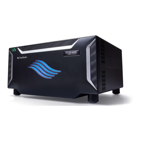
Barrett 4050 HF SDR Transceiver
BCM40500/10
© Barrett Communications
s/w v1.6.2
Head Ofce:
Barrett Communications Pty Ltd
47 Discovery Drive, Bibra Lake, WA 6163 Australia
Tel: +61 8 9434 1700 Fax: +61 8 9418 6757
Email: [email protected]
www.barrettcommunications.com.au


iii
Compliance
Barrett 4000 series transceivers comply to the following communications stand-
ards:
• Australian / New Zealand Standard
• MF and HF Radio Communications.
Equipment in the land mobile service utilising single sideband suppressed car-
rier emission:
• AS/NZS 4770:2000
• FCC Part 90.
• FCC Part 87
• Industry Canada (IC) RSS-125 Issue 2
Barrett 4000 series transceivers comply to the following EMC standard:
• EN301 489-1 V 1.4.1 (2002-08).
Barrett 4000 series transceivers comply to the following electrical safety stand-
ard:
• EN60950-1:2002.
FCC RF Exposure Compliance Statement
The Barrett 4000 Series transceivers have been evaluated and comply with the
Federal Communications Commission (FCC) RF exposure limits for the General
Population/Uncontrolled exposure environment.
In addition, the transceivers comply with the following standards and guide-
lines:
• FCC 96-326, Guidelines for Evaluating the Environmental Effects of
Radio-Frequency Radiation
• FCC OET Bulletin 65 Edition 01-01 (2001) Supplement C, Evaluating Com-
pliance with FCC
• Guidelines for Human Exposure to Radio Frequency Electromagnetic Fields
• ANSI/IEEE C95.1-1992, IEEE Standard for Safety Levels with Respect to
Human Exposure to Radio Frequency Electromagnetic Fields, 3 kHz to 300
GHz
• ANSI/IEEE C95.3-1992, IEEE Recommended Practice for the Measurement
of Potentially Hazardous Electromagnetic Fields - RF and Microwave.

iv
RF Exposure Warning
To ensure optimal transceiver performance and to avoid exposure to excessive
electromagnetic elds, the antenna system must be installed according to the
instructions provided.
High voltages exist on the antenna during transmission and tuning. Do not
touch the antenna during these activities. RF burns may result.
Install the grounding system or counterpoise as directed to prevent RF burns
from any metal part of the transceiver.
Safe working distance is based on continuous exposure to CW type transmis-
sions, as set out in the ICNIRP Exposure Guidelines (1998) for occupational expo-
sure. Safe working distance can be reduced with normal voice communication.
For IC and FCC compliance, when the 4050 transceiver is used at a power level
of 150 watts PEP and a 13 dBi gain antenna, the antenna(s) used with this
Transceiver should be located at least 6 metres from the operator and should
not be co-located or operating in conjunction with any other antenna or trans-
mitter.
For IC and FCC compliance, when the 4050 transceiver is used in a vehicular
environment at a power level of 150 watts PEP with 1.5 dBi gain antenna, the
antenna(s) used with this transceiver should be located at least 1.6 metres from
the operator and should not be co-located or operating in conjunction with any
other antenna or transmitter.
Typical antenna types and minimum separation dis-
tance:
Antenna type Gain
(dBi)
PEP
(W)
Minimum safe sepa-
ration distance (m)
Typical
Environ-
ment
Automatic tuned and whip 0 150 1.3 Vehicle
Magnetic Loop 1.5 150 1.6 Vehicle
Multi-wire Broadband 5 150 2.4 Fixed
Log-Periodic 13 150 5.9 Fixed
Automatic tuned and Whip 0 100 1.0 Vehicle
Magnetic Loop 1.5 100 1.2 Vehicle
Multi-wire Broadband 5 100 1.8 Fixed
Log-periodic 13 100 4.4 Fixed
Automatic tuned and Whip 0 30 0.5 Vehicle

v
Antenna type Gain
(dBi)
PEP
(W)
Minimum safe sepa-
ration distance (m)
Typical
Environ-
ment
Magnetic Loop 1.5 30 0.7 Vehicle
Multi-Wire Broadband 5 30 1.1 Fixed
Log-Period 13 30 2.7 Fixed
The above antennas are identied for reference only. It is important that the
installer and operator maintain a minimum safe separation distance with the
actual antenna used in the installation and to insure, in a vehicular environ-
ment, that the transmitter is only used when persons outside the vehicle are at
least the recommended lateral distance away.
The image below shows an example of minimum recommended separation dis-
tance from antenna in a vehicular environment.
1.3 M
1.3 M
1.6 M
2019 Automatic Tuning Mobile HF Antenna
2018 Mobile Magnrtic Loop HF Antenna
Note: References to Vehicular environments and minimum safe oper-
ating distances relate to persons outside the vehicle only and not to
persons within the vehicle.

vi

vii
Contents
INTRODUCTION 1 ................................................................................1
Introduction ..................................................................................................2
Important Disclosure............................................................................. 3
Terms & Abbreviations .......................................................................... 4
The Barrett 4050 HF Transceiver ....................................................................6
Transceiver Front .................................................................................. 6
Transceiver Rear .................................................................................... 7
Starting the Transceiver.................................................................................8
Keypad ..........................................................................................................8
Display ..........................................................................................................9
Swipe Menu........................................................................................ 10
BASIC OPERATION 2 ..........................................................................13
Basic Conguration Diagram.......................................................................14
Antenna Type ..............................................................................................15
Selecting a Channel.....................................................................................16
Making a Voice Call .....................................................................................17
Making an Emergency Call ..........................................................................18
Receiving an Emergency Call .......................................................................19
SELCALL 3...........................................................................................21
Overview .....................................................................................................22
Important Selective Calling Information......................................................23
Summary of Calling Systems .......................................................................24
Setting up a Self ID .....................................................................................25
Setting up Contacts.....................................................................................26
Additional Contact Information .......................................................... 28
Making a Selcall ..........................................................................................29

viii
Beacon Call ......................................................................................... 30
Selcall.................................................................................................. 31
Telcall .................................................................................................. 32
Advanced Call History ......................................................................... 35
Advanced Selcall Functions .........................................................................39
Selcall Settings .................................................................................... 39
Pagecall............................................................................................... 40
GPS Request........................................................................................ 41
GPS Position........................................................................................ 43
Status Call........................................................................................... 44
Secure Call .......................................................................................... 45
Hangup Call ........................................................................................ 46
Selcall Networks.................................................................................. 47
BASIC SETTINGS 4 ..............................................................................49
System Information.....................................................................................50
Head Device ID.................................................................................... 50
Serial Number ..................................................................................... 50
Version Information ............................................................................ 50
Transceiver Options............................................................................. 51
Conguration Pack Information.......................................................... 51
SDV/4026 Serial Number..................................................................... 51
General Settings..........................................................................................52
Audio Settings.............................................................................................53
Display Settings...........................................................................................54
PROGRAMMING 5 ..............................................................................55
Channel Programming ................................................................................56
Programming Channels Through the Front Panel................................ 56
Free Scroll Rx/Tx...........................................................................................60

ix
Programming Via USB .................................................................................61
ADVANCED OPERATION 6 ..................................................................63
ARINC Call ...................................................................................................64
Audio - Advanced........................................................................................65
Rx Conguration................................................................................. 65
Tx Conguration ................................................................................. 65
Audio Bandwidth................................................................................ 65
Line Audio........................................................................................... 66
Line Follows Digital Voice.................................................................... 66
Line Out Level ..................................................................................... 66
Line In Level ........................................................................................ 66
Audio Record ...................................................................................... 66
Custom Filter Bandwidth .................................................................... 66
Collective Call..............................................................................................67
Digital Voice ................................................................................................68
Frequency Hopping .....................................................................................69
Selecting the Hopping Band................................................................ 69
Entering the Hopping PIN ................................................................... 69
Enabling and Disabling Hopping......................................................... 69
GPS Push .....................................................................................................70
GPS Push State.................................................................................... 70
Privacy Key .......................................................................................... 70
I/O Settings..................................................................................................71
RS232 Connection............................................................................... 71
RS232 Network Encryption ................................................................. 71
RS232 Out........................................................................................... 71
RS232 Baud Rate................................................................................. 72
EXT Alarm Type ................................................................................... 72

x
Antenna 2........................................................................................... 72
Modes .........................................................................................................73
Mute (Squelch)............................................................................................74
Network ......................................................................................................76
Noise Reduction (NR) ..................................................................................78
RF Settings ..................................................................................................79
Rx Preamp........................................................................................... 79
Tx Over Beep ....................................................................................... 79
Transmit Timeout ................................................................................ 80
Noise Blanker ...................................................................................... 80
Tx Power Level .................................................................................... 80
AGC Hang ........................................................................................... 80
Broadcast Filter ................................................................................... 80
Scanning .....................................................................................................81
Add a Scan Table................................................................................. 82
Table Selection .................................................................................... 82
Scan Settings ...................................................................................... 83
Scan Tables.......................................................................................... 84
Delete a Scan Table ............................................................................. 84
Security Settings..........................................................................................85
OEM Selcall Privacy Key....................................................................... 85
Frequency Hop PIN.............................................................................. 86
Frequency Hop Rate............................................................................ 86
OEM Secure Type ................................................................................ 86
OEM Secure Key.................................................................................. 86
Secure Digital Voice/Data Key.............................................................. 86
Selcall Secure Call Hop Rate ................................................................ 87
Selcall Secure Call Code ...................................................................... 87

xi
Remote Access Password .................................................................... 87
SDV Programming Mode .................................................................... 87
Enable Power On PIN .......................................................................... 87
Tuning .........................................................................................................88
INSTALLATION 7 .................................................................................89
Introduction ................................................................................................90
Installing a Secondary Control Head............................................................91
Installing Dual Antennas .............................................................................92
Mobile Installations.....................................................................................93
Mobile Pack ........................................................................................ 93
2019 Automatic Tuning Mobile HF Antenna ..................................... 100
2018 Mobile Magnetic Loop Antenna............................................... 111
Base Station Installations ..........................................................................113
Site Selection Recommendations ..................................................... 113
Cooling Fan...............................................................................................117
Installing the Cooling Fan ................................................................. 117
Antennas .......................................................................................... 118
912 Multi wire Broadband Dipoles.................................................... 118
4017 Automatic Tuning Horizontal Dipole Antenna.......................... 120
4011 Automatic Antenna Tuner for Base Station Installations .......... 123
911 Automatic Antenna Tuner for Base Station Installations ........... 128
Marine Installations...................................................................................133
APPENDICES 8..................................................................................138
Appendix 1 - Specications .......................................................................139
General ............................................................................................. 139
Receiver............................................................................................. 140
Transmitter........................................................................................ 141
Appendix 2 - Connectors...........................................................................142

xii
Power Connector .............................................................................. 142
GPS Connector.................................................................................. 142
Aux Control Head / BoB Connector ................................................... 143
Auxiliary Connector........................................................................... 143
ATU Connector.................................................................................. 145
Microphone Connector ..................................................................... 145
Control Head Rear Panel Connector .................................................. 146
Cooling Fan Connector...................................................................... 146
Appendix 3 - Overview of HF Operation ....................................................147
HF Propagation ................................................................................. 147
Radio Wave Propagation................................................................... 148
Factors Which Affect HF/SSB Communications.................................. 149
HF Communications Compared with VHF or UHF Short Distance Commu-
nications .................................................................................... 150
Appendix 4 - BITE Test ..............................................................................151
Tests.................................................................................................. 151
Limited 3 Year Warranty Statement...........................................................154
Contact Details.................................................................................. 155

1
INTRODUCTION 1
This chapter contains the following sections:
• Introduction
• The Barrett 4050 HF Transceiver
• Activating the Transceiver
• Display

2
BARRETT 4050 HF SDR TRANSCEIVER - INTRODUCTION
Introduction
The Barrett 4050 Transceiver is an SDR based HF SSB transceiver with a fre-
quency range of 1.6 to 30 MHz in transmit and 250kHz -30MHz. The Barrett
4050 is designed using the latest technology enabling a physically small pack-
age with a full feature complement.
Designed to operate in the most arduous environments, as encountered in off-
road vehicles, vessels and aircraft, the Barrett 4050 will provide many years of
efcient and trouble free service.
The Barrett 4050 supports features such as Selective Call (Selcall), direct dial
telephone connection to base stations tted with telephone interconnect sys-
tems (Telcall), GPS location, 2G and 3G ALE (Automatic Link Establishment), fre-
quency hopping, digital voice, data transmission and remote diagnostics. These
features make the Barrett 4050 HF Transceiver one of the most economical and
versatile HF transceiver available today.
The Barrett 4050 Transceiver caters for increased use of HF data transmission for
Internet email access and point-to-point data applications, by providing a com-
prehensive data modem interface port, high speed transmit-to-receive switch-
ing, a high stability frequency standard and an efcient cooling system option.
The Barrett 4050 Transceiver can be operated in either a local (desktop) con-
guration for base station applications or, with the addition of an inexpensive
mobile pack, in a remote control (trunk mount) conguration for mobile appli-
cations.
The Barrett 4050 Transceiver can be controlled from all major mobile and desk-
top platforms. Full remote control is available via the Barrett 4050 Remote Con-
trol app, providing unprecedented access to all transceiver functionality across
all major platforms.
Operated from 12 V DC to 24 V DC power supplies, the transmitter is rated
at 125-150 watt PEP in voice mode and is protected from over-voltage or
reverse-voltage application.
Up to 1000 channels (depending on the 4050 variant), are available to be eld
or workshop programmable. Auxiliary features such as Selcall, Telcall, scanning,
mute status, alarm system etc. can be individually enabled or disabled for every
channel as required to suit your operation.
Teamed with other matching Barrett products which include antennas, power
supplies, vehicle tracking packages and HF modems, the Barrett 4050 HF Trans-
ceiver becomes a powerful tool, providing solutions to many long distance
communication requirements.

3
BARRETT 4050 HF SDR TRANSCEIVER - INTRODUCTION
Please refer to the 4000 Series IP Connectivity/Networking Guide (P/N
BCM40507) for information regarding using the 4050 transceiver with a Break
out Box or WiFi adapter for IP connectivity and networking.
Important Disclosure
Please note that this manual describes all the features of the
4050 HF SDR Transceiver and that some variants of the 4050
may not have all the features installed.
Illustrations may show accessories, optional equipment or
other features which are not part of the standard specica-
tion and are not available in individual countries.

4
BARRETT 4050 HF SDR TRANSCEIVER - INTRODUCTION
Terms & Abbreviations
Term /
Abbreviation
Denition
ALE Automatic Link Establishment
AM Amplitude Modulation
ARINC A set of standards as established by Aeronautical Radio,
Incorporated (ARINC).
Call History A list containing details of the last thirty calls received.
CCIR One of many possible Selcall formats as dened by the
Consultative Committee on International Radio (CCIR).
CF Custom Filter selection
CW Continuous Wave (used for Morse code)
dB Decibels
dBm Power ratio in decibels (dB) of the measured power refer-
enced to one milliwatt (mW).
DSP Digital Signal Processing
ESU Encryption Synchronisation Unit
FHSS Frequency Hopping Spread Spectrum
GPS Global Positioning System
HF High Frequency
Identication
Code
The unique reference identication (ID) of a transceiver
(not serial number).
INT International Selcall format
LCD Liquid Crystal Display
LSB Lower Sideband
LUF Lowest Usable Frequency
MUF Maximum Usable Frequency
OEM Original Equipment Manufacturer, OEM Selcall Format
OTG On-The-Go (USB)
PCB Printed Circuit Board
PEP Peak Envelope Power
PIN Personal Identication Number

5
BARRETT 4050 HF SDR TRANSCEIVER - INTRODUCTION
Term /
Abbreviation
Denition
PSTN Public Switched Telephone Network
Receive Only
Channel
A channel that receives calls but does not transmit calls.
Revertive Tone /
Signal
An acknowledgment signal automatically transmitted
from a station receiving a Selcall.
RF Radio Frequency
RFDS Royal Flying Doctor Service
Scan Table A list of channels used when scanning for incoming
calls.
Selcall Selective Calls
SCF Suppressed Carrier Frequency
SSL Signal Strength Level
Station ID The ID of the station being called (the receiving station’s
Self ID).
Self ID The programmed address identication number of a local
station. (Used by other stations to call you.)
SMS Short Message Service
SSB Single Sideband (a transmission format)
Telcall Telephone call using the Selective Call protocol.
USB Upper Sideband
VSWR Voltage Standing Wave Ratio

6
BARRETT 4050 HF SDR TRANSCEIVER - INTRODUCTION
The Barrett 4050 HF Transceiver
Transceiver Front
1Power button which combines switching the transceiver on and off
with adjusting the volume.
This will be represented as throughout the manual
2USB / WiFi Socket
3Touchscreen
4Keypad
5Microphone socket
1 2 3 4
5

7
BARRETT 4050 HF SDR TRANSCEIVER - INTRODUCTION
Transceiver Rear
1GND Use this stud to attach a ground (earth) connection.
For example, vehicle chassis
2
DC INPUT
12 - 24 V DC Power input for use with the 4022 power supply
3GPS Input for GPS receiver (P/N BCA40009) for vehicle
tracking / location applications
4
ANT Main antenna socket
5ATU Interface for Barrett automatic tuning mobile antenna
and marine automatic antenna tuners
6AUXILIARY 25-way auxiliary interface
7SPEAKER Output for loudspeaker (P/N BCA40015)
8AUX CONTROL
HEAD / BoB
This can be used to attach a secondary con-
trol head (via a six metre cable) in addition to
the front panel. This can also be used to attach a
or linear system.
1 2 3 4
56
7
8

8
BARRETT 4050 HF SDR TRANSCEIVER - INTRODUCTION
Starting the Transceiver
Ensure the transceiver is attached to a power source appropriate for your situa-
tion. Please refer to the Basic Operation section on page 13.
Momentarily press the on button,
, to turn the transceiver on.
Pressing the same button for three
seconds powers down the trans-
ceiver.
Alternately, pressing the same but-
ton briey brings up the Power
Button Menu allowing the trans-
ceiver to be rebooted or shut
down.
Holding down the Power Button
for 10 seconds will power off the
transceiver.
Keypad
Key Function
Channel Up /
Scroll up
Channel Down /
Scroll down
Scroll left and right
Key Function
Enter /
Set a menu item
Make a call
Clear /
Back one step
There are seven keys on the keypad. Some keys have multiple functions assigned
to them depending on when or how long the key is pressed.
Press the and buttons together to initiate an emergency call.
See page 18 for further information.
Other manuals for 4050 HF SDR
3
Table of contents
Other Barrett Transceiver manuals
Barrett
Barrett 2030 Specification sheet
Barrett
Barrett 2000 Series User manual
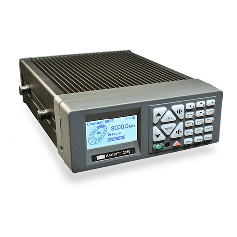
Barrett
Barrett 2050 User manual

Barrett
Barrett 2050 Specification sheet
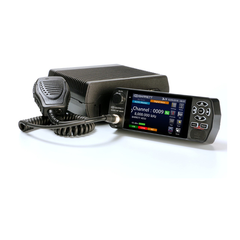
Barrett
Barrett 4050 HF SDR Specification sheet
Barrett
Barrett PRC-4090 Specification sheet
Barrett
Barrett HF SDR 4000 Series User manual

Barrett
Barrett 550 User manual
Barrett
Barrett 4050 HF SDR User manual
Barrett
Barrett 950 HF SSB Specification sheet

