Icom ID-5100A Installation guide

This device complies with Part 15 of the FCC Rules. Operation is
subject to the following two conditions: (1) this device may not cause
harmful interference, and (2) this device must accept any interference
received, including interference that may cause undesired operation.
WARNING: MODIFICATION OF THIS DEVICE TO RECEIVE CEL-
LULAR RADIOTELEPHONE SERVICE SIGNALS IS PROHIBITED
UNDER FCC RULES AND FEDERAL LAW.
BASIC MANUAL
New2001
ID-5100A
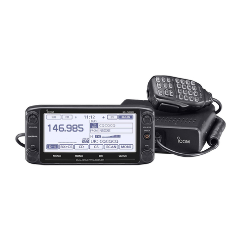
DUAL BAND TRANSCEIVER
ID-5100E
The photo shows the ID-5100E version.

i
New2001New2001
FOREWORD
Thank you for purchasing this fine Icom product. The ID-
5100A and ID-5100E d u a l b a n d t r a n s c e i v e r are designed
and build with Icom’s superior technology and craftsmanship
combining traditional analog technologies with the new digital
technology, Digital Smart Technologies for Amateur Radio (D-
STAR), for a balanced package.
With proper care, this product should provide you with years
of trouble-free operation.
We thank you for making your ID-5100A or ID-5100E your
transceiver of choice, and hope you agree with Icom’s philos-
ophy of “technology first.” Many hours or research and devel-
opment went into the design of your ID-5100A or ID-5100E.
EXPLICIT DEFINITIONS
WORD DEFINITION
RDANGER! Personal death, serious injury or an ex-
plosion may occur.
RWARNING! Personal injury, fire hazard or electric
shock may occur.
CAUTION Equipment damage may occur.
NOTE Recommended for optimum use. No risk
of personal injury, fire or electric shock.
IMPORTANT
READ ALL INSTRUCTIONS carefully and completely
before using the transceiver.
SAVE THIS INSTRUCTION MANUAL— This in-
struction manual contains basic operating instructions for the
ID-5100A/ID-5100E.
Icom, Icom Inc. and the Icom logo are registered trademarks of Icom
Incorporated (Japan) in Japan, the United States, the United King-
dom, Germany, France, Spain, Russia and/or other countries.
Adobe and Adobe Reader are either registered trademarks or trade-
marks of Adobe Systems Incorporated, in the United States and/or
other countries.
Microsoft, Windows and Windows Vista are registered trademarks of
Microsoft Corporation in the United States and/or other countries.
The Bluetooth word mark and logos are registered trademarks
owned by Bluetooth SIG, Inc. and any use of such marks by Icom
inc. is under license.
Android and the Android logo are trademarks of Google, Inc.
All other products or brands are registered trademarks or trademarks
of their respective holders.

New2001New2001
ii
SUPPLIED ACCESSORIES
The following accessories are supplied with the transceiver.
DWhen using the GPS receiver
• GPS signals cannot pass through metal objects. When us-
ing the ID-5100A or ID-5100E inside a vehicle, you may not
receive GPS signals. We recommend you use it near a win-
dow. Please avoid the areas where:
1. The driver’s view will be blocked.
2. The air bags could deploy.
3. The unit becomes a driving obstacle.
• The Global Positioning System (GPS) is built and operated
by the U.S. Department of Defence. The Department is re-
sponsible for accuracy and maintenance of the system. Any
changes by the Department may affect the accuracy and
function of the GPS system.
• When the GPS receiver is activated, please do not cover
the remote controller with anything that will block the satel-
lite signals.
• The GPS receiver may not work if used in the following loca-
tions:
1. Tunnels or high-rise buildings
2. Underground parking lots
3. Under a bridge or viaduct
4. In remote forested areas
5. Under bad weather conditions (rainy or cloudy day)
IMPORTANT NOTES
DC power
cable
Controller cable
(3.5 m:11.4 ft)
Microphone
(HM-207)
CD
(Instruction manual
[Full Manual])
Operating guide
(Includes the CS-5100
c l o n i n g s o f t w a r e )
Spare fuse
(FGB 20 A)
Microphone
hanger
Instruction manual
[Basic Manual]

iii
New2001New2001
DTouch screen precautions
Briefly touching the controller’s touch operates the function.
• The touch screen may not properly work when LCD protec-
tion film or sheet is attached.
• Touching the screen with nger nails, sharp topped object
and so on, or touching the screen hard may damage the
screen.
• Tablet PC’s operations such as ick input, pinch in and pinch
out cannot be performed with this touch screen (based on
the resistance film type).
DTouch screen maintenance
• If the touch screen becomes dusty or dirty, wipe it clean with
a soft, dry cloth.
• When you wipe the touch screen, be careful not to push it
too hard or scratch it with finger nails. Otherwise you may
damage the touch screen.
DTouch operation
(Short touch):If the display is touched briefly, one short
beep sounds.
(Long touch): If the display is touched for 1 second, one
short and one long beep sound.
• After the beep, the operation is enabled.
In the instruction manual, the touch operation is described
as shown below.
If the display is touched briefly, one short beep
sounds.
If the display is touched for 1 second, one short and
one long beep sound.
DAbout the Touch area
Areas you can touch for various operations are shown to the
right.
• This page describes the main operations of the touch screen.
See the instruction manual for other operations.
ABOUT THE TOUCH SCREEN

iv
ID-5100
Function menu selection:
Displays
the Function menu list:
Displays the QUICK Menu:
Mutes the audio:
• Releases mute when rotating [DIAL],
[VOL] or [SQL], or operating a key,
touch screen or microphone.
Function menu
operations
• The following operations
are examples.
Sets MAIN band to the
right side:
Sets MAIN band to the right side:
Dual or Single band display selection:
• In the Single band, touch [B] to set the B band as
the MAIN band.
Displays the
DR screen:
• D-STAR settings can
easily be made.
Home CH selection:
• Selects the Home CH that you
set in the QUICK Menu.
Home CH setting:
Displays the Menu screen:
“kHz” tuning selection:
Tuning step selection:
Displays the Memory
Write window:
Writes to a blank
CH:
Scan type
selection:
Starts a scan:
• The last used scan
starts.
Dual or Single band display selection:
Operating mode
selection:
“MHz” tuning
selection:
Operating band
selection:
TX power selection:
• MAIN band: Used for TX or radio’s settings
• SUB band: Used for the Dualwatch operation
ABOUT THE TOUCH SCREEN (Continued)
Displays the Monitor
function:
Sets the Mode:
Displays the date
and time: Displays the GPS
menu window:

v
New2001 New2001
The following instructions and installers are included on the
CD.
•BasicManual
Basic operating instructions, and are the same instructions
that are in this manual
•FullManual
Full operating instructions, and more details are described
than in this manual
•CloningSoftwareInstaller
Installer for the CS-5100 cloning software
•CloningSoftwareInstructionmanual
Instructions for the CS-5100 cloning software installation
and use
•OperatingGuide
Operating guide for using the touch screen, Menu items and
Quick menu items. Contains the same information that is in
the supplied leaflet.
•HAMradioTerms
A glossary of HAM radio terms
•Adobe®Reader®Installer
Installer for Adobe®Reader®
ABOUT THE SUPPLIED CD
DStarting the CD
Insert the CD into the CD drive.q
• Double click “Menu.exe” on the CD.
• Depending on the PC setting, the Menu screen shown
below is automatically displayed.
Click the desired button to open the file.w
• To close the Menu screen, click [Quit].
A PC with the following Operating System is required.
• Microsoft®Windows® 8.1, Microsoft®Windows® 8, Micro-
soft®Windows® 7, Microsoft®Windows Vista®or Microsoft®
Windows® XP
To read the guide or instructions, Adobe®Reader®is required. If you
have not installed it, please install the Adobe®Reader®on the CD or
downloaded it from Adobe Systems Incorporated’s web
site.
Quits the menu screenInstalls the Adobe®Reader®
Opens the
Glossary
Installs the
CS-5100
Opens the Full
manual
Opens the
Operating Guide
Opens the Basic manual
(this manual)
Opens the
CS-5100
Instructions

New2001
vi
1
2
3
4
5
6
7
8
9
10
11
12
13
14
15
16
17
18
19
RDANGER HIGH VOLTAGE! NEVER touch an an-
tenna connector during transmission. This may result in an
electrical shock or burn.
RWARNING RF EXPOSURE! This transceiver emits
Radio Frequency (RF) energy. Extreme caution should be ob-
served when operating this transceiver. If you have any ques-
tions regarding RF exposure and safety standards please
refer to the Federal Communications Commission Office of
Engineering and Technology’s report on Evaluating Compli-
ance with FCC Guidelines for Human Radio Frequency Elec-
tromagnetic Fields (OET Bulletin 65).
RWARNING! NEVER operate the transceiver while
driving a vehicle. Safe driving requires your full attention—
anything less may result in an accident.
RWARNING! NEVER operate the transceiver with an
earphone or other audio accessories at high volume levels.
Hearing experts advise against continuous high volume op-
eration. If you experience a ringing in your ears, reduce the
volume level or discontinue use.
RWARNING! NEVER connect the transceiver to an AC
outlet. This may pose a fire hazard or result in an electric
shock.
RWARNING! NEVER connect the transceiver to a
power source of more than 16 V DC. This will damage the
transceiver.
RWARNING! NEVER connect the transceiver to a
power source using reverse polarity. This will damage the
transceiver.
RWARNING! NEVER cut the DC power cable between
the DC plug and fuse holder. If an incorrect connection is
made after cutting, the transceiver may be damaged.
RWARNING! NEVER let metal, wire or other objects
touch any internal part or connectors on the rear panel of the
transceiver. This may result in an electric shock or this could
cause a fire or damage the transceiver.
RWARNING! NEVER operate or touch the transceiver
with wet hands. This may result in an electric shock or may
damage the transceiver.
RWARNING! Immediately turn the transceiver power
OFF and remove the power cable if it emits an abnormal
odor, sound or smoke. Contact your Icom dealer or distributor
for advice.
CAUTION: NEVER expose the transceiver to rain, snow
or any liquids.
PRECAUTIONS

vii
New2001 New2001
CAUTION: NEVER change the internal settings of the
transceiver. This may reduce transceiver performance and/or
damage to the transceiver.
CAUTION: NEVER place the transceiver where normal
operation of the vehicle may be hindered or where it could
cause bodily injury.
DO NOT operate the transceiver near unshielded electrical
blasting caps or in an explosive atmosphere.
DO NOT push the PTT when not actually desiring to trans-
mit.
DO NOT use harsh solvents such as benzine or alcohol to
clean the transceiver, as they will damage the transceiver’s
surfaces. If the transceiver becomes dusty or dirty, wipe it
clean with a soft, dry cloth.
DO NOT use or place the transceiver in areas with tem-
peratures below –10°C (+14°F) or above +60°C (+140°F). Be
aware that temperatures on a vehicle’s dashboard can exceed
+80°C (+176°F) in direct sunlight, resulting in permanent dam-
age to the transceiver if left there for extended periods.
DO NOT place the transceiver in excessively dusty environ-
ments or in direct sunlight.
DO NOT place the transceiver against walls or putting anything
on top of the transceiver. This will obstruct heat dissipation.
Place the transceiver in a secure place to avoid inadvertent
use by children.
During mobile operation, NEVER place the transceiver
where air bag deployment may be obstructed.
During mobile operation, DO NOT place the transceiver
where hot or cold air blows directly onto it.
During mobile operation, DO NOT operate the transceiver
without running the vehicle’s engine. When the transceiver’s
power is ON and your vehicle’s engine is OFF, the vehicle’s
battery will soon become exhausted.
Make sure the transceiver power is OFF before starting the
vehicle engine. This will avoid possible damage to the trans-
ceiver by ignition voltage spikes.
During maritime mobile operation, keep the transceiver and
microphone as far away as possible from the magnetic navi-
gation compass to prevent erroneous indications.
BECAREFUL! The rear panel will become hot when op-
erating the transceiver continuously for long periods of time.
Use Icom microphones only (supplied or optional). Other
manufacturer’s microphones have different pin assignments,
and may damage the transceiver.
PRECAUTIONS (Continued)

New2001
viii
TABLE OF CONTENTS
FOREWORD ......................................................................... i
EXPLICIT DEFINITIONS....................................................... i
IMPORTANT .......................................................................... i
SUPPLIED ACCESSORIES................................................. ii
IMPORTANT NOTES............................................................ ii
ABOUT THE TOUCH SCREEN........................................... iii
ABOUT THE SUPPLIED CD ................................................ v
PRECAUTIONS................................................................... vi
TABLE OF CONTENTS......................................................viii
NEW FUNCTIONS ....................................... x–xii
1 PANEL DESCRIPTION ........................... 1–10
Controller — Front panel■.............................................1
Controller — Display (Touch screen)■..........................2
Main unit — Front and rear panels■.............................7
Microphone (HM-207)■.................................................8
2 BASICOPERATION.............................. 11–18
Power ON the power■.................................................11
Setting audio volume and squelch level■....................11
Selecting a tuning step■..............................................11
Selecting the watch mode■.........................................12
Selecting the operating band■....................................13
Direct frequency input■...............................................14
Selecting the Mode and the DR function■..................15
Transmitting■...............................................................16
Selecting the operating mode■...................................17
Lock function■.............................................................17
Home channel function■.............................................18
Speech function■........................................................18
3 MEMORY MANAGEMENT.................... 19–20
Writing Memory channels■.........................................19
Checking the Memory contents■................................19
4 D-STAR OPERATION............................ 21–54
Unique features of D-STAR■.......................................21
D-STAR Introduction■.................................................22
About the DR (D-STAR Repeater) function■...............22
Ways to Communicate with the DR function■.............23
Enter your call sign into the transceiver■....................24
Register your call sign at a gateway repeater■...........27
Making a Simplex call■...............................................29
Accessing repeaters■.................................................31
Using the RX history■.................................................33
Capturing a call sign■.................................................35
Making a Local area call■...........................................37
Making a Gateway Repeater call■..............................39
Calling an individual station■......................................41
New2001New2001
ix
New2001
TABLE OF CONTENTS (Continued)
Troubleshooting■.........................................................43
Reflector operation■....................................................45
Updating the repeater list■..........................................51
5 RECORDING A QSO ONTO
AN SD CARD ........................................ 55–58
About the SD card■.....................................................55
Inserting the SD card■................................................56
Recording a QSO audio■............................................57
Playing recorded audio■.............................................58
Removing the SD card■..............................................58
6 GPS OPERATION ................................. 59–60
GPS operation■..........................................................59
Checking your GPS position■.....................................59
7 MENU SCREEN .................................... 61–78
Menu item selection■..................................................61
Menu items and Default settings■...............................62
8 INSTALLATION AND CONNECTIONS. 79–84
Connect controller to main unit■.................................79
Microphone connection■.............................................79
DC power supply connection■....................................79
Controller■installation ................................................80
Installing in a vehicle■.................................................81
Antenna installation■...................................................82
Battery connection■....................................................83
9 MAINTENANCE .................................... 85–86
Resetting■...................................................................85
Power protect function■..............................................86
Spurious signals■.......................................................86
Fuse replacement■.....................................................86
10 INFORMATION............................................ 87
COUNTRY CODE LIST .................................................87
FCC INFORMATION......................................................87
INDEX......................................................... 88–90

New2001
x
NEW FUNCTIONS
New2001
NEW FUNCTIONS
1Two band monitoring in the DV mode
2Add-on functions for D-PRS
This section describes the new functions built into the ID-
5100A/E.
• See the Full Manual for more details.
The transceiver can simultaneously monitor two different fre-
quencies in the DV mode.
For example, while operating in the Simplex mode on the
MAIN band, you can monitor a D-STAR repeater on the SUB
band.
• While receiving or transmitting a DV signal on the MAIN band, DV
mode audio from the SUB band will be muted.
• See Section 7 of the Full Manual for details.
D-PRS enables the transceiver to transmit or receive the Ob-
ject, Item or Weather data in addition to position data.
With the D-PRS add-on functions, you can receive informa-
tion such as an event, traffic, emergency or weather while
making a voice call in the DV mode.
• See Section 8 of the Full Manual for details.
D-PRS “TX FORMAT” screen in the Menu screen.
(GPS > GPS TX Mode > D-PRS > TX Format)
Touch to set the
GPS TX format
to “D-PRS.”
Appears
MAIN band
(You can hear the
received audio)
SUB band
(The received audio
is muted.)

xi
NEW FUNCTIONS
New2001
xi
New2001New2001
3Memory management
4Import and Export the CSV format file
5Near FM Repeater search function
You can easily edit the Memory or Call channel contents in
the “MANAGE MEMORY” screen. You can view the contents
on a list. (p. 19)
You can easily import and export the repeater list. (p. 53)
• An SD card is required.
You can enter FM repeater data using the DR function.
The function can find only FM repeaters in your transceiver's
repeater list.
• See Section 6 of the Full Manual for details.
“MANAGE MEMORY” item
Memory edit screen
When FM repeater is selected.

New2001
xii
NEW FUNCTIONS
New2001
NEW FUNCTIONS
6Bluetooth®operation
Installing the optional UT-133 Bluetooth®u n i t allows you to
use a variety of Bluetooth®products.
• See Section 15 of the Full Manual for details.
Bluetooth®
VS-3
Android™ device
(third party)
7Calling through a reflector
When you link to a reflector, you can listen to activity on all
the repeaters that are connected to the reflector, and easily
make contacts. (p. 45)

1
New2001New2001
PANEL DESCRIPTION
1
New2001
ID-5100
qq
ww
e
rr
t
y u i o
Display
qSQUELCH CONTROL [SQL]
Rotate to adjust the squelch level. (p. 11)
• Normally, set the squelch level to where noise and the “BUSY”
icon just disappear. (closed)
• You can use the S-Meter Squelch or Attenuator function by rotat-
ing the control clockwise beyond the center position. (Section 2
of the Full Manual)
wVOLUME CONTROL [VOL]
Rotate to adjust the audio level. (p. 11)
About control’s operation
In the Dualwatch mode, the left side controls are used for
the left side band, and the right side controls are used for
the right side.
In the Single watch mode, the left side controls are used for the
A band, and the right side controls are used for the B band.
■Controller — Front panel eMAIN UNIT CONNECTOR
Connect the controller to the Main unit using the supplied
control cable. (p. 79)
rTUNING DIAL [DIAL]
In the VFO mode, rotate to select the operating fre-➥
quency, and in the Memory mode, rotate to select a
Memory channel. (p. 15)
In the Menu screen or Quick Menu window, rotate to➥
select a desired option or value.
While scanning, rotate to change the scanning direc-➥
tion. (Section 4 of the Full Manual)
tPOWER KEY [SPEECH]
Hold down for 1 second to turn power ON or OFF. (p. 11)➥
Push to audibly announce the operating frequency,➥
mode or a selected call sign. (p. 18)
y[MENU] (Touch screen) (p. 61)
Touch to open the Menu screen.
u[HOME] (Touch screen)
Touch to select the Home channel.➥
Touch for 1 second to set the Home channel. (p. 18)➥
i[DR] (Touch screen) (p. 16)
Touch to open the DR screen.
o[QUICK] (Touch screen)
Touch to open the Quick Menu window.➥
Touch for 1 second to mute the audio. (p. 11)➥

New2001
2
1
PANEL DESCRIPTION
New2001
1
PANEL DESCRIPTION
q w
Dualwatch mode Single watch mode (A band)
Single watch mode (B band)
In the Single watch mode: A band In the Single watch mode: B band
■Controller — Display (Touch screen)
qMAIN/SUBBANDICON
In the Dualwatch mode, this icon will be highlighted to indi-
cate the MAIN band.
“ ” is displayed on the SUB band. (p. 12)
wTONE/DIGITAL SQUELCH ICONS
Displayed when you set any tone or digital squelch function.
(Mode: FM/FM-N)
“TONE” is displayed while the Repeater Tone Encoder➥
is ON.
“TSQL➥S” is displayed while the Pocket Beep func-
tion with CTCSS is ON.
“TSQL” is displayed while the Tone squelch function is ON.➥
“DTCS➥S” is displayed while the Pocket Beep func-
tion with DTCS is ON.
“DTCS” is displayed while the DTCS squelch function➥
is ON.
“TSQL-R” is displayed while the Reverse Tone squelch➥
function is ON.
“DTCS-R” is displayed while the Reverse DTCS squelch➥
function is ON.
(Mode: DV)
“DSQL➥S” is displayed while the Pocket Beep func-
tion with Digital Call Sign squelch function is ON.
“DSQL” is displayed while the Digital Call Sign squelch➥
function is ON.
“CSQL➥S” is displayed while the Pocket Beep function
with Digital Code squelch function is ON.
“CSQL” is displayed while the Digital Code squelch➥
function is ON.

3
1PANEL DESCRIPTION
New2001 New2001
eMODE ICONS
Displays the selected operating mode. (p. 17)
• In the DV mode, “ ” is displayed when you set the GPS TX
Mode to “D-PRS” or “NMEA.”
rPRIORITY ICON
Displayed when Priority watch is turned ON.
tBluetooth®ICON (Section 15 of the Full Manual)
Displayed when you make a Bluetooth®connection be-
tween your transceiver that has the optional UT-133 Blu-
etooth®u n i t installed and a Bluetooth®device.
yVOX ICON (Section 15 of the Full Manual)
Displayed when you make a Bluetooth®connection be-
tween your transceiver that has the optional UT-133 Blue-
tooth®u n i t installed and the optional VS-3 Bluetooth®h e a d -
s e t , and the VOX function is ON.
uEMR/BK/PacketLoss/AutoReplyICON
“EMR” is displayed when you select the Enhanced➥
Monitor Request (EMR) mode.
“BK” is displayed when you select the Break-in (BK)➥
mode.
“L” is displayed when packet loss has occurred.➥
“➥” is displayed when you select the Automatic Reply
function.
iCLOCK READOUT
Displays the current time.
oRECORD ICON
Displayed while recording.
• “ ” is displayed while the transceiver is recording.
• “ ” is displayed while the recording is paused.
e r t y u i o !1!0
!2
Dualwatch mode Single watch mode (A band)
Single watch mode (B band)
Controller — Display (Touch screen) (Continued)■
@5
!3
!4
!9 !5!6!8 !7@0
@1
@2
@3
@4

New2001
4
1
PANEL DESCRIPTION
1
PANEL DESCRIPTION
!0 SD ICON (p. 56)
“➥” is displayed when a SD card is inserted.
“➥” and “ ” alternately blinks while accessing the SD
card.
!1 GPS ICON
Displays the status of the GPS receiver. (p. 59)➥
“➥ì” is displayed when you set the GPS alarm. (Section
8 of the Full Manual)
!2 AUTO POWER OFF ICON (p. 61)
Displayed when the Auto power OFF function is ON.
!3 DR SCREEN (pp. 16, 22)
Displays the DR screen where the D-STAR settings are made.
!4BUSY/MUTEICON (Section 2 of the Full Manual)
“BUSY” is displayed while a signal is being received or➥
the squelch is open.
“BUSY” blinks while the monitor function is activated.➥
“MUTE” is displayed while the mute is activated.➥
!5 SKIP ICON (Section 4 of the Full Manual)
Displays the selected Skip function.
• “SKIP”: Memory skip
• “PSKIP”: Program skip
!6MEMORYCHANNELNUMBER (p. 15)
Displays the selected Memory channel number, Mem-➥
ory Bank, and so on.
“WX” is displayed when the Weather channel mode is➥
ON.*
*Only the USA version transceiver.
!7 MEMORY ICON (p. 15)
Displayed when the Memory mode is selected.
!8 S/RF METER (Section 2 of the Full Manual)
Displays the relative signal strength of the receive signal.➥
Displays the output power level of the transmit signal.➥
!9 FUNCTION MENU DISPLAY
Displays the touch key, according to the selected function
menu group. (p. 5)
@0 FUNCTION GROUP ICON
Displays the selected function group (F-1 to F-4, D-1 to
D-3) (p. 5)
@1 POWER ICONS (Section 2 of the Full Manual)
Displays the output power level of the transmit signal➥
in three levels.
In the Dualwatch mode:➥
“H” is displayed when you select high power.
“M” is displayed when you select mid power
“L” is displayed when you select low power.
@2 S-METER SQUELCH/ATTENUATOR ICONS
(Section 2 of the Full Manual)
“S SQL” is displayed when the S-meter squelch is ac-➥
tivated.
“ATT” appears when the Attenuator function is activated.➥
@3 MEMORY NAME DISPLAY (Section 3 of the Full Manual)
In the Memory mode, displays the programmed memory
name.
@4 FREQUENCY READOUT
Displays the operating frequency. (p. 14)
@5 DUPLEX ICON (Section 11 of the Full Manual)
“DUP–” is displayed when minus duplex is selected, and
“DUP+” is displayed when plus duplex is selected.

5
1PANEL DESCRIPTION
New2001 New2001
Controller — Display (Touch screen) (Continued)■
DFunction menu
You can toggle the function group to select the desired func-
tion keys to operate the transceiver, depending on the trans-
ceiver’s operating mode or status.
Each function key works for the MAIN band.
• In the VFO, Memory or Call channel mode, you can select
the F-1 to F-4 menus.
• In the DR screen, you can select the D-1 to D-3 menus.
Touch the group icon to toggle the function group.➥
Touch the group icon for 1 second to display the function➥
menu list.
q w e r t
q[V/M]
Touch to toggle between the VFO and Memory modes.
w[CALL]
Touch to turn the Call channel mode ON or OFF.
e[MW]
Touch to open the Memory Write window.➥
In the VFO mode or the DR screen, touch for 1 second➥
to store the operating data into the blank channel.
In the Memory or Call channel mode, touch for 1 sec-➥
ond to open the Memory Edit screen.
r[SCAN]
Touch to open the Scan type setting window.➥
Touch for 1 second to start the last used scan.➥
t[MONI]
Touch to turn the Monitor function ON or OFF.
u i o !0y
y[SKIP]
(Appears in the Memory mode.)
Touch to open the Scan Skip setting window.
u[DTMF]
Touch to open the DTMF send window.
i[VOICE]
When you insert an SD card into the transceiver’s SD card
slot, touch to open the “VOICE TX” screen.
o[LOW]
Touch to open the TX power setting window.
!0 [GPS]
Touch to open the GPS item setting window.

New2001
6
1
PANEL DESCRIPTION
1
PANEL DESCRIPTION
!2 !3 !4 !5!1
!1 [DUP]
Touch to open the duplex direction setting window.
!2 [TONE]
(Displayed only when in the FM/FM-N mode.)
Touch to open a Tone function setting window.
!3 [REC]
When you insert an SD card into the transceiver’s SD card
slot, touch to start recording a QSO (communication) au-
dio.
!4 [SCOPE]
Touch to open the sweep item setting window.
!5 [≈]
(Displayed only when you select a sweep operation in
[SCOPE](!4).)
Touch to start a single sweeping.➥
Touch for 1 second to start a continuous sweeping.➥
While sweeping, touch to stop it.➥
!7 !8!6
(Displayed only when in the DV mode.)
!6 [RX>CS]
Touch to open the “RX>CS” screen.➥
Touch for 1 second to set the received station call sign➥
as the destination (UR) call sign.
!7 [CD]
Touch to open the “RX HISTORY” screen.
!8 [CS]
Touch to open the “CALL SIGN” screen.
!7 !8 !9 @0!6
!9 [SCAN]
Touch to open the DR scan setting window.➥
Touch for 1 second to start the last used scan.➥
@0 [MONI]
Touch to turn the Digital Monitor function ON or OFF.
u i o !0@1
@1 [SKIP]
Touch to open the skip setting window for the Access➥
repeater scan.
Touch for 1 second to set the skip setting in the Func-➥
tion menu.
@2 !3e
@2 [DSQL]
(Appears in the DV mode.)
Touch to open the Digital squelch function setting window.
If you set the operating mode to “DV” in the VFO mode,
[DSQL] is displayed instead of [TONE] on the F-3 menu.

7
1PANEL DESCRIPTION
New2001 New2001
q w e r t y u i
o
■Main unit — Front and rear panels
qSD CARD SLOT [SD CARD]
Insert an SD card (purchase separately). (p. 52)
wCONTROLLER CONNECTOR [CONTROLLER]
Connects to the Controller using the supplied control cable.
eMICROPHONE CONNECTOR [MIC]
Plug in the supplied microphone (HM-207) or the optional
microphone (HM-154).
rANTENNA CONNECTOR
Connect a 50 øimpedance of antenna with a PL-259 con-
nector.
The transceiver has a built-in duplexer, so you can use a
144 and 430 MHz dual-band antenna without needing an
external duplexer.
tCOOLING FAN
The cooling fan for heat dissipation.
You can select the Fan control option in the Menu screen,
and automatically starts to rotate when you begin transmit-
ting, or continuously rotates from power ON.
yDATA JACK [DATA]
Connect a PC through the optional data communication
cable, for cloning or low-speed data communication in the
DV mode. (Section 13 of the Full Manual)
uEXTERNAL SPEAKER JACK 1 [SP1]
iEXTERNAL SPEAKER JACK 2 [SP2]
Connect to an 8 ohm external speaker.➥
• When you connect external speakers to [SP1] and
[SP2], the A band (left side display) audio is heard
from [SP1] and the B band (right side display) audio is
heard from [SP2].
• When you connect an external speaker to [SP1], the
A and B band audio is heard from [SP1]. In this case,
the internal speaker is disabled.
• When you connect an external speaker to [SP2], the
A band (left side display) audio is heard from the inter-
nal speaker and the B band (right side display) audio
is heard from the external speaker.
The [SP2] jack is used for external control of the trans-➥
ceiver. (Section 1 of the Full Manual)
Other manuals for ID-5100A
4
This manual suits for next models
1
Table of contents
Other Icom Transceiver manuals

Icom
Icom IC-970A User manual

Icom
Icom IC-746 Installation guide

Icom
Icom IC-E80D User manual

Icom
Icom IC-M90E User manual

Icom
Icom IC-M323 User manual

Icom
Icom IC-F14 User manual

Icom
Icom IC-575A User manual

Icom
Icom IC-M91D Installation and operating instructions

Icom
Icom IC-77 User manual

Icom
Icom IC-F621 User manual