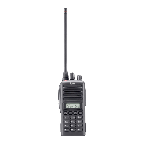
Icom iF4261DT User manual

i
INTRODUCTION
Thank you for choosing this Icom product.
This product is designed and built with Icom’s state
of the art technology and craftsmanship. With proper
care, this product should provide you with years of
trouble-free operation.
IMPORTANT
FIRST, CAREFULLY READ PRECAUTIONS
AND INSTRUCTIONS that are provided with the
transceiver.
SAVE THIS OPERATING GUIDE— This operating
guide contains additional important operating
instructions for the IC-F4261DT and the IC-F6061D
uhf transceivers.
Icom, Icom Inc. and Icom logo are registered trademarks of
Icom Incorporated (Japan) in Japan, the United States, the
United Kingdom, Germany, France, Spain, Russia, Australia,
New Zealand, and/or other countries.
NXDN is a trademark of Icom Incorporated and JVC
KENWOOD Corporation.
All other products or brands are registered trademarks or
trademarks of their respective holders.
Icom is not responsible for the destruction or damage to
the Icom transceiver, if the malfunction is because of:
• Force majeure, including, but not limited to, res,
earthquakes, storms, oods, lightning, other natural
disasters, disturbances, riots, war, or radioactive
contamination.
• The use of Icom transceivers with any equipment that is
not manufactured or approved by Icom.
Previous view

1-1
Section 1ACCESSORIES
Supplied accessories.............................................................. 1-2
Attaching accessories............................................................. 1-3
DFlexible antenna (Portable)............................................. 1-3
DBattery pack (Portable) ................................................... 1-3
DBelt clip (Portable) .......................................................... 1-4
DConnector cover (Portable)............................................. 1-5
Previous view

1ACCESSORIES
1-2
Supplied accessories
The following accessories are supplied.
NOTE: Some accessories are not supplied, or the
shape is different, depending on the transceiver
version.
zPortable type transceiver
zMobile type transceiver
Microphone*1Microphone hanger
and screws set
Microphone
hanger cable
DC power cable Sponges*3
Flat washers
Spring washers
Bracket bolts
Mounting screws
(5×12)
Self-tapping screws
(5×16)
Nuts
Function name
stickers*2
*2
Not supplied, depending on the
transceiver version.
Used for labelling the programmable
function keys according to their
assinged functions.
Used for optional unit installation.
*1
Mounting bracket
*3
Battery pack Belt clip
Connector cover
(with screw)
Flexible antenna
Previous view

1ACCESSORIES
1-3
Attaching accessories
DFlexible antenna (Portable)
Connect the supplied exible antenna to the antenna
connector.
DBattery pack (Portable)
CAUTION: DO NOT attach or detach the battery
pack when the transceiver is wet or soiled. This may
result in water or dust getting into the transceiver/
battery pack and may damage the transceiver.
To attach:
Slide the battery pack in the direction of the arrow (q)
until the battery release button makes a ‘click’ sound.
NOTE: Push on the bottom of the pack until the
release button is rmly locked.
To detach:
Push the battery release button in the direction of the
arrow (w), as shown to the right.
The battery pack is then removed.
NOTE: Keep the battery pack terminals clean. It’s a
good idea to occasionally clean them.
CAUTION:
• DO NOT carry the transceiver by holding only the
antenna.
• DO NOT connect an antenna other than those
listed in the INSTRUCTIONS.
• Transmitting without an antenna may damage the
transceiver.
q
w
Battery release
button
Battery pack
Previous view

1ACCESSORIES
1-4
Accessory attachments (Continued)
DBelt clip (Portable)
To attach:
1. Remove the battery pack from the transceiver, if it
is attached.
2. Slide the belt clip in the direction of the arrow until
the belt clip locks and makes a ‘click’ sound.
BE CAREFUL! Don’t break your ngernail.
To detach:
1. Remove the battery pack from the transceiver, if it
is attached.
2. Lift the tab up (q), and slide the belt clip in the
direction of the arrow (w).
w
q
Previous view

1ACCESSORIES
1-5
Accessory attachments (Continued)
DConnector cover (Portable)
To attach:
1. Attach the connector cover over the multi-
connector. (q)
2. Tighten the screw. (w)
To detach:
1. Remove the screw. (z)
2. Detach the connector cover, and then connect an
optional equipment. (x)
CAUTION: DO NOT detach the connector cover
when optional equipment is not in use. Otherwise the
terminals of the multi-connector may be shorted by
a metal object, or become rusty by water intrusion.
This could damage the transceiver.
q
w
Multi-connector
Connector
cover
z
x
Previous view

2-1
Section 2PANEL DESCRIPTION
Front, top and side panels (for the Portable type transceiver)
.. 2-2
DAbout the Status indicator............................................... 2-2
DAbout the Multi-connector............................................... 2-2
DAbout the Software key functions ................................... 2-2
Function display (for the Portable type transceiver) ............... 2-3
Front, top and side panels (for the Mobile type transceiver) .. 2-4
DAbout the Status indicator............................................... 2-4
DAbout the Microphone connector.................................... 2-4
DAbout the Software key functions ................................... 2-4
Function display (for the Mobile type transceiver).................. 2-5
Assignable keys...................................................................... 2-6
DPortable type................................................................... 2-6
DMobile type ..................................................................... 2-6
Assignable Software key functions......................................... 2-7
Previous view

2PANEL DESCRIPTION
2-2
Front, top and side panels (for the Portable type transceiver)
DAbout the Status indicator
• Lights red while transmitting.
• Lights green while receiving a signal, or when the
squelch is open.
• Blinks red when the internal temperature is higher
than the threshold level, and the transmit output
power is reduced.
DAbout the Multi-connector
Connects to an optional speaker microphone or
headset.
CAUTION: DO NOT use the transceiver without the
connector cover or the optional equipment attached.
The transceiver meets IP67 requirements for dust-
tight and waterproof protection only when the
connector cover or the optional HM-184 is attached.
DAbout the Software key functions
NOTE: Dealers can assign the Software key
functions to the dealer assignable keys.
LSee page 2-7 for details.
* Dealer assignable
Antenna connector
[Rotary Selector]
[Emer]*
[Side1]*
[PTT]
[Side2]*
[Side3]*
10-keypad
[P0]*, [P1]*,
[P2]*, [P3]*
Function Display
Microphone
Speaker
Status Indicator
Multi-connector
[VOL]
GPS Receiver
Previous view

2PANEL DESCRIPTION
2-3
Function display (for the Portable type transceiver)
q SIGNAL STRENGTH ICON
Displays the relative receive signal strength.
wLOW POWER ICON
Displayed when the output power is set to Low.
LWhenthebatterychargedecreasestoaspecied
level, low power is automatically selected.
e AUDIBLE ICON
Displayed when the channel is in the Audible
(unmute) mode.
r SCRAMBLER/ENCRYPTION ICON
In the Analog mode
Displayed when the Voice Scrambler function is
ON.
In the Digital mode
zDisplayed when the Voice Encryption function
is ON.
zBlinks when decoding an encrypted signal.
t SCAN ICON
zBlinks while scanning.
zDisplayed when the scan pauses.
y MESSAGE ICON
Displayed when the transceiver receives a
message (Short Data Message or Status
Message).
u BELL ICON
Displayed when a matching signal is received,
depending on the presetting.
i GPS/COMPANDER ICON
z“ ” is displayed when the GPS receiver
acquires GPS signals from satellites and the
“GPS Indicator” setting is ON.
z“ ” is displayed when the Compander function
is activated and the “GPS Indicator” setting is
OFF.
o BATTERY ICON
Displayed or blinks to indicate the battery status.
Indication
Battery
status Full Mid Charging
required
Battery
exhausted
blinks when the battery is over charged.
blinks when the battery is exhausted.
!0 ALPHANUMERIC READOUT
Displays the operating channel number, channel
name, Menu contents, and so on.
LDepending on the “Display Line” setting, characters
are displayed in 1 line or 2 lines on the display. In this
operating guide, the display illustration is described
as having characters displayed in 2 lines.
!1 KEY ICONS
Displays the assigned Software key function of the
[P0], [P1], [P2] and [P3] front panel keys.
001 ch-01
Icom Inc.
SET ZONE LOCK H/L
ENTBACK
PRIVATE
ID 0000002
dPMRCLRMENUCALL
0001
1234
CALLMONTXCEBIIS
CONTACT
ENTBACK
CONTACT
qwe rt y u i o
!0
!1
Previous view

2PANEL DESCRIPTION
2-4
Front, top and side panels (for the Mobile type transceiver)
DAbout the Software key functions
NOTE: Dealers can assign the Software key
functions to the dealer assignable keys.
LSee page 2-7 for details.
DAbout the Status indicator
• Lights red while transmitting.
• Lights green while receiving a signal, or when the
squelch is open.
[VOL]
Status indicator Up/Down keys*
Power key [ ]
[P0], [P1], [P2], [P3], [P4]*
Function display Speaker
Microphone
connector
DAbout the Microphone connector
Connect the supplied or optional microphone.
CAUTION: DO NOTconnectnon-specied
microphones. The pin assignments may be different
and may damage the transceiver.
About the microphone:
The supplied or optional microphone has a PTT switch
and a hanger.
• The following functions are usable when you put
the microphone ON hook, or take it OFF hook
(depending on the presetting):
- Automatic scan starts when you put it ON hook.
- Scan is paused or canceled when you take it OFF
hook.
- Automatically selects the Priority A channel when
you take it OFF hook.
- Sets to the Inaudible (mute) mode when you put it
ON hook.
-
Sets to the Audible (unmute) mode when you take
it OFF hook
.
* Dealer assignable
Previous view

2PANEL DESCRIPTION
2-5
Function display (for the Mobile type transceiver)
q SIGNAL STRENGTH ICON
Displays the relative receive signal strength level.
Weak
Receive Signal level
Strong
w LOW POWER ICON
Displayed when the output power is set to Low.
e AUDIBLE ICON
Displayed when the channel is in the Audible
(unmute) mode.
rGPS/COMPANDER ICON
zDisplayed when the GPS receiver acquires GPS
signals from satellites and the “GPS Indicator”
setting is ON.
zDisplayed when the Compander function is
activated and the “GPS Indicator” setting is
OFF.
t SCRAMBLER/ENCRYPTION ICON
In the Analog mode
Displayed when the Voice Scrambler function is
ON.
In the Digital mode
zDisplayed when the Voice Encryption function
is ON.
zBlinks when decoding an encrypted signal.
yBELL ICON
Displayed when a matched signal is received,
depending on the presetting.
u MESSAGE ICON
Displayed when the transceiver receives a
message (Short Data Message or Status
Message).
iALPHANUMERIC DISPLAY
Displays the operating channel number, channel
name, Menu contents, and so on.
LDepending on the “Display Line” setting, characters
are displayed in 1 line or 2 lines on the display. In this
operating guide, the display illustration is described
as having characters displayed in 2 lines.
o ACTIVATED KEY ICON
Displayed above the key assigned as [Scan],
[Scan Add/Del(Tag)], [Lock], [Talk Around],
[Surveillance], [Individual], [Talkgroup], while that
key is activated.
Icom Inc.
o
qw erty u
i
Previous view

2PANEL DESCRIPTION
2-6
Assignable keys
DPortable type
Dealers can assign the Software key functions to the
following keys.
[Emer], [Side1], [Side2], [Side3], [P0], [P1], [P2], and
[P3]. [Emer]
[Side1]
[Side2]
[Side3] [P0], [P1],
[P2], [P3]
DMobile type
Dealers can assign the Software key functions to the
following keys.
[Up], [Down], [P0], [P1], [P2], [P3], and [P4].
[Up], [Down]
[P0], [P1], [P2], [P3], [P4]
Previous view

2PANEL DESCRIPTION
2-7
Assignable function Portable Mobile Digital Analog Ref.
Disable ✓ ✓ ✓ ✓ p. 2-9
Null ✓ ✓ ✓ ✓ p. 2-9
CH Up
CH Down ✓ ✓ ✓ ✓ p. 2-9
Zone ✓ ✓ ✓ ✓ p. 2-9
Zone Up
Zone Down ✓ ✓ ✓ ✓ p. 2-9
Menu ✓ ✓ ✓ ✓ p. 2-9
Scan Start/Stop ✓ ✓ ✓ ✓ p. 2-9
Scan Add/Del (Tag) ✓ ✓ ✓ ✓ p. 2-9
Prio A
Prio B ✓ ✓ ✓ ✓ p. 2-9
Prio A (Rewrite)
Prio B (Rewrite) ✓ ✓ ✓ ✓ p. 2-9
MR-CH 1
MR-CH 2
MR-CH 3
MR-CH 4
✓ ✓ ✓ ✓ p. 2-9
Moni ✓ ✓ ✓ ✓ p. 2-9
Public Address N/A ✓ ✓ ✓ p. 2-9
RX Speaker N/A ✓ ✓ ✓ p. 2-10
Light ✓ ✓ ✓ ✓ p. 2-10
Lock ✓ ✓ ✓ ✓ p. 2-10
Lone Worker ✓ ✓ ✓ ✓ p. 2-10
High/Low ✓ ✓ ✓ ✓ p. 2-10
Tone/RAN CH Select ✓ ✓ ✓ ✓ p. 2-10
C.Tone CH Ent ✓ ✓ ✓ ✓ p. 2-10
Talk Around ✓ ✓ ✓ ✓ p. 2-10
Wide/Narrow ✓ ✓ ✓ ✓ p. 2-10
Emergency ✓ ✓ ✓ ✓ p. 2-10
Surveillance ✓ ✓ ✓ ✓ p. 2-10
Scrambler/Encryption ✓ ✓ ✓ ✓ p. 2-10
Compander ✓ ✓ ✓ ✓ p. 2-11
Hook Scan N/A ✓ ✓ ✓ p. 2-11
User Set Mode ✓ ✓ ✓ ✓ p. 2-11
OPT1 Out
OPT2 Out
OPT3 Out
✓ ✓ ✓ ✓ p. 2-11
OPT1 Momentary
OPT2 Momentary
OPT3 Momentary
✓ ✓ ✓ ✓ p. 2-11
Assignable Software key functions
☞Continued on the next page
✓: Applicable
N/A: Not Applicable
Previous view

2PANEL DESCRIPTION
2-8
Assignable function Portable Mobile Digital Analog Ref.
Digital Button ✓ ✓ ✓ N/A p. 2-11
Individual ✓ ✓ ✓ N/A p. 2-11
Talkgroup ✓ ✓ ✓ N/A p. 2-11
Reset ✓ ✓ ✓ N/A p. 2-11
Sp. Func 1
Sp. Func 2 ✓ ✓ ✓ ✓ p. 2-11
Status Up
Status Down ✓ ✓ ✓ N/A p. 2-12
Status ✓ ✓ ✓ N/A p. 2-12
Message ✓ ✓ ✓ N/A p. 2-12
Power OFF Emergency N/A ✓ ✓ ✓ p. 2-12
GPS Display ✓ ✓ ✓ ✓ p. 2-12
Assignable Software key functions (Continued)
✓: Applicable
N/A: Not Applicable
Previous view

2PANEL DESCRIPTION
2-9
Assignable Software key functions (Continued)
Disable
Set to disable the key.
NOTE: This key function is assignable to only
[Ext. Emer].
Null
No function.
CH Up, CH Down
zPush to select an operating channel.
LWhen ‘Memory Channel’ is assigned to [Rotary
selector], this function is disabled.
zAfterpushingspecickeys,pushtoselectan
option, setting, and so on.
Zone
Push to display the zone name (or zone number).
Then push [CH Up] or [CH Down] to select an
operating zone.
LWhen ‘Zone’ is assigned to [Rotary selector], this function
is disabled.
Zone Up, Zone Down
Push to select an operating zone.
TIP: What is a “zone”?
Certain channels are grouped together and assigned
to a zone according to their intended use.
For example, ‘Staff A’ and ‘Staff B’ are assigned to a
“Business” zone, and ‘John’ and ‘Cindy’ are assigned
to a “Private” zone.
Menu
Push to display the Menu screen.
LDepending on the presetting, you may be able to make
various calls, select various functions and adjust the
transceiver settings in the Menu screen. See section 5 for
details.
LIn the Menu screen, you cannot use the assigned key
functions.
Scan Start/Stop
zPush to start or cancel a Scan.
LWhen a scan started with the Power ON Scan or Auto
Scan function, pushing this key pauses the scan. The
paused scan resumes after the preset time period has
passed.
zHold down for 1 second to display the scan list.
Then push [CH Up] or [CH Down] to select a list.
NOTE: When Mode Dependent Scan is ON, the
user may not be able to display the Scan list,
depending on the presetting.
Scan Add/Del (Tag)
zYou can add a channel to, or delete it from a
selected Scan list.
1. Push this key to display the current Scan list.
2. Push [CH Up] or [CH Down] to select a list.
3. Push this key again to add a channel to, or
delete it from the selected list.
• When a channel is added to the selected Scan list,
“SCANON”isbrieydisplayed.
• When a channel is deleted from the selected Scan
list,“SCANOFF”isbrieydisplayed.
4. Hold down this key for 1 second to return to the
Standby mode.
zWhile a Scan is paused by detecting a signal on a
channel (except for primary or secondary channel),
push this key to remove the channel from the Scan
list.
TIP: When the Nuisance Delete function is ON,
the removed channel is automatically added to the
Scan list again, after the Scan is canceled.
Priority A, Priority B
Push to select the Priority A or Priority B channel.
Priority A (Rewrite), Priority B (Rewrite)
zPush to select the Priority A or Priority B channel.
zHold down for 1 second to assign the operating
channel to the Priority A or Priority B channel.
Memory channel 1, Memory channel 2,
Memory channel 3, Memory channel 4
Push to select memory channel 1, 2, 3, or 4.
Monitor
zPush to turn the CTCSS (DTCS) squelch mute ON
or OFF.
zWhile holding down this key, the transceiver opens
any squelch, or releases any mute.
zDepending on the presetting, holding down this key
for 1 second may cancel the Scan.
Public Address (For the Mobile type transceivers)
Push to activate the Public Address (PA) function.
And then, speak into the microphone while holding
down [PTT].
LWhen the PA function is activated, the audio output can
be separately controlled from the transceiver by pushing
[CH Up] or [CH Down].
NOTE: This function is usable when an external
unit,suchasaaudioamplier,speaker,andsoonis
connected to the D-sub 25-pin connector.
Previous view

2PANEL DESCRIPTION
2-10
Assignable Software key functions (Continued)
RX Speaker (For the Mobile type transceivers)
Push to turn the RX Speaker function ON or OFF.
LWhen the RX Speaker function is turned ON, the received
audio can be heard through an external speaker that is
connected to the D-sub 25-pin connector.
NOTE:
• This function is usable when an external speaker
that is connected to the D-sub 25-pin connector.
• This function is useful when the user is out of the
vehicle.
• The audio output level is linked to the transceiver’s
volume control.
Light
Push to turn ON the backlight for about 5 seconds,
even if the backlight setting is OFF.
Lock
Hold down for 1 second to turn the Key Lock function
ON or OFF.
LAll assignable keys except the following are electronically
locked: [Monitor], [Light], [Lock], [Emergency], and
[Surveillance]. Also, [PTT] and [Power] are usable.
Lone Worker
Push to turn the Lone Worker function ON or OFF.
LIfnooperationoccursduringthespeciedperiod,the
Lone Worker function automatically makes the transceiver
enter the Emergency mode.
NOTE: To use the Lone Worker function, set the
related settings using the programming software.
High/Low
Push to select the transmit output power level
temporarily or permanently, depending on the
presetting.
Tone/RAN CH Select
In the Analog mode
Push to display the C.Tone channel select screen.
Then push [CH Up] or [CH Down] to select a tone
frequency or code. After selecting, push this key again
to save.
In the Digital mode
Push to display the RAN channel select screen. Then
push [CH Up] or [CH Down] to select a RAN code.
After selecting, push this key again to save.
C.Tone CH Ent
In the Analog mode
Push to display the C.Tone channel select screen.
Then push [CH Up] or [CH Down] to select a tone
frequency or code. After selecting, push this key again
to save.
Talk Around
Push to turn the Talk Around function ON or OFF.
LThe Talk Around function equalizes the transmit
frequency to the receive frequency, for direct (Simplex)
communication.
Wide/Narrow
In the Analog mode
Push to temporarily set the channel width to Wide* or
Narrow.
*The Wide channel width is not usable for the USA version
transceivers.
Emergency
1. Hold down during the Emer SW ON Timer period
to enter the Emergency mode.
2. After the Start Timer period has passed, an
Emergency call is automatically transmitted once,
or repeatedly.
NOTE: Set the related settings using the programming
software.
LHold down during the Emer SW OFF Timer
period to cancel the Emergency function, before
transmitting an Emergency call.
Surveillance
Push to turn the Surveillance function ON or OFF.
LWhen this function is turned ON, the beep is not heard
and the backlight and the Status indicator do not light,
even when a signal is received, or a key is pushed.
Scrambler/Encryption
In the Analog mode
Push to turn the Voice Scrambler function ON or OFF.
LThe Voice Scrambler function provides private
communication between stations by using a scrambled
code.
In the Digital mode
Push to turn the Encryption function ON or OFF.
LThe Voice or Data Encryption function provides private
communication between stations by using an Encryption
Key and Key ID.
Previous view

2PANEL DESCRIPTION
2-11
Assignable Software key functions (Continued)
Compander
In the Analog mode
Push to turn the Compander function ON or OFF.
LThe Compander function reduces noise components on
the transmit audio to provide clear communication.
Hook Scan (For the Mobile type transceivers)
Push to temporarily turn the Hook Scan function ON
or OFF.
User Set Mode
zHold down for 1 second to enter the User Set
mode. In the User Set mode, push this key to select
an item, and then push [CH Up] or [CH Down] to
change the value or setting.
zHold down for 1 second again to exit the User Set
mode.
OPT1 Out, OPT2 Out, OPT3 Out
Push to output the control signal to the selected option
connector.
OPT1 Momentary, OPT2 Momentary,
OPT3 Momentary
While holding down this key, the control signal is
output to the selected option connector.
Digital Button
In the Digital mode
zPush to enter the Application Selection mode.
zPush to enter the ID Selection mode from the
Application Selection mode.
zHold down for 1 second to toggle the call type
between Individual and Talkgroup.
LAfter selecting the call type, the transceiver
automatically enters the Application Selection mode.
TIP: When the “Digital/Individual/Talkgroup Key”
item is set to “ID Select,” this key function differs, as
shown below.
zPush to enter the ID Selection mode.
zPush to enter the Application Selection mode from
the ID Selection mode.
Individual
In the Digital mode
zPush to set the call type to “Individual,” then
automatically enter the Application Selection mode.
zPush to enter the ID Selection mode from the
Application Selection mode.
zHold down for 1 second to return to the Standby
mode.
TIP: When the “Digital/Individual/Talkgroup Key”
item is set to “ID Select,” this key function differs, as
shown below.
zPush to set the call type to “Individual,” then
automatically enter the ID Selection mode.
zPush to enter the Application Selection mode from
the ID Selection mode.
Talkgroup
In the Digital mode
zPush to set the call type to “Talkgroup,” then
automatically enter the Application Selection mode.
zPush to enter the ID Selection mode from the
Application Selection mode.
zHold down for 1 second to return to the Standby
mode.
TIP: When the “Digital/Individual/Talkgroup Key”
item is set to “ID Select,” this key function differs, as
shown below.
zPush to set the call type to “Talkgroup,” then
automatically enter the ID Selection mode.
zPush to enter the Application Selection mode from
the ID Selection mode.
Reset
In the Digital mode
zPush to reset the destination ID and call type to the
default, if they have manually been changed.
zPush to cancel the Talk Back function, if it is
activated.
zWhile in the Audible mode, push to return to the
Inaudible mode.
zWhile in the Selection mode (Example: Application,
Message and Status Message), push to return to
the Standby mode.
LIn that case, the transceiver resets the destination ID,
call type, and Talk Back function to the default.
Sp. Func 1, Sp. Func 2
Reserved for future function.
Previous view

2PANEL DESCRIPTION
2-12
Assignable Software key functions (Continued)
Status Up, Status Down
In the Digital mode
zPush to enter the Status Message Selection mode.
zWhile in the Status Message Selection mode, push
to select a message.
zWhen a received Short Data Message (SDM) is
displayed, push to manually scroll the message.
zWhen an SDM that contains more than 12
characters is displayed, push to manually scroll the
message.
Status
In the Digital mode
Push to enter the Status Message Selection mode.
Then push [CH Up] or [CH Down] to select a Status
message. After selecting, push [PTT] to send the
message to the currently selected station or group.
Or, push this key again to set.
LSee page 7-11 for details.
Message
In the Digital mode
Push to enter the Message Selection mode. Then
push [CH Up] or [CH Down] to select a message. After
selecting, push [PTT] to send the message to the
currently selected station or group. Or, push this key
again to set.
LSee pages 7-15, 7-19 for details.
Power OFF Emergency
(For the Mobile type transceivers)
While holding down this key, turn OFF the transceiver
to activate the Power OFF Emergency function.
InformationL
• This function makes the transceiver transmit Emergency
calls, even though it appears to be powered OFF.
• When the function is activated, any key operation, hanger
action and Lone Worker function become invalid, as well
as the Status indicator and speaker become the same as
being powered OFF.
On the other hand, the transceiver can transmit Emergency
calls according to the Emergency settings, and the
Ambience Listening function is also activated, if it is set.
• To cancel the function and restore the transceiver, turn ON
the transceiver.
GPS Position
Push to display the GPS Position screen in the Menu
mode.
Previous view

3-1
Section 3BASIC OPERATION
Turning ON the transceiver .................................................... 3-2
DAdjusting the audio level................................................. 3-2
DEntering the password .................................................... 3-2
Selecting a Zone..................................................................... 3-3
DSelecting a Zone............................................................. 3-3
Selecting a channel ................................................................ 3-5
DSelecting an operating channel ...................................... 3-5
DSelecting the Priority A or B channel............................... 3-6
DRewriting the Priority A or B channel ............................. 3-7
DSelecting a Continuous tone channel ............................. 3-8
DSelecting a RAN channel................................................ 3-9
Receiving and transmitting ................................................... 3-10
DTransmitting notes ........................................................ 3-10
Previous view
This manual suits for next models
1
Table of contents
Other Icom Transceiver manuals
Popular Transceiver manuals by other brands

Kenwood
Kenwood NX-5900 Service manual

Iridium
Iridium 9603 Developer's guide

Technisonic Industries Limited
Technisonic Industries Limited TiL-90-6R/8.33 Installation and operating instructions

Abell
Abell TH-307 instruction manual

Yaesu
Yaesu FT-817ND Brochure & specs

Sommerkamp
Sommerkamp TS-630S instruction manual

Maxon
Maxon PM200 user manual

AirTurn
AirTurn BT-105 user manual

TMC Radio
TMC Radio SRM9000X8 Service manual

Expert Electronics
Expert Electronics SunSDR2 DX manual

Standard Communications
Standard Communications GX1500VAA Service manual

Microwave Data Systems
Microwave Data Systems MDS FIVE Series USER INTERFACE MANUAL