Icom IC-7700 Guide

2-1
INSTALLATION AND CONNECTIONS IC-7700
■Unpacking ……………………………………………………………… 2-2
■Main dial attachment …………………………………………………… 2-2
■Rack mounting handle detachment …………………………………… 2-3
■Selecting a location …………………………………………………… 2-3
■Grounding ……………………………………………………………… 2-4
■Antenna connection …………………………………………………… 2-4
■USB-Memory connection ……………………………………………… 2-4
■Required connections ………………………………………………… 2-5
DFront panel …………………………………………………………… 2-5
DRear panel …………………………………………………………… 2-5
■Advanced connections ………………………………………………… 2-6
DFront panel …………………………………………………………… 2-6
DRear panel—1 ……………………………………………………… 2-6
DRear panel—2 ……………………………………………………… 2-7
■Linear amplifier connections …………………………………………… 2-8
DConnecting the IC-PW1/EURO …………………………………… 2-8
DConnecting a non-Icom linear amplifier …………………………… 2-8
■Transverter jack information …………………………………………… 2-9
■FSK and AFSK (SSTV) connections ………………………………… 2-9
■Microphone connector information ………………………………… 2-10
■Microphones (options) ………………………………………………… 2-10
DSM-20 ……………………………………………………………… 2-10
DHM-36 ……………………………………………………………… 2-10
■Accessory connector information …………………………………… 2-11
CAUTION!: The transceiver weighs approx. 24 kg (53 lb).
Always have two people available to carry, lift or
turn over the transceiver.

2-2
■Unpacking After unpacking, immediately report any damage to the
delivering carrier or dealer. Keep the shipping cartons.
For a description and a diagram of accessory equip-
ment included with the IC-7700, see ‘Supplied acces-
sories’ on p. iii of this manual.
■Main dial attachment The main dial is shipped unattached to the transceiver
to prevent possible damage to the dial shaft or rotary
encoder during shipping. Please attach the dial as de-
scribed below.
qSlide the dial brake adjustment to the right position
(Fig. 1).
•The dial brakes move inward as shown.
wRemove the rubber cover of the main dial (Fig. 2).
eInsert the main dial set-screw into the screw hole of
the main dial, then tighten the screw until the screw
extends into the shaft hole out slightly using sup-
plied hexagonal wrench (2 mm) (Fig. 2).
•Be careful that the screw does not extend out more than
1 mm (1/32 in).
rAttach the main dial as illustrated (Fig. 3).
•Be careful to match the correct orientation of the flat face
of the shaft and the screw hole of the dial knob.
tTighten the screw using supplied hexagonal wrench
as illustrated (Fig. 3).
yInstall the rubber cover of the main dial (Fig. 4).
Then adjust the main dial brake as desired.
✔
When re-packing and shipping the transceiver:
Slide the dial brake adjustment to the right position,
then detach the main dial when re-packing and ship-
ping the transceiver at any time.
2INSTALLATION AND CONNECTIONS
Dial brake adjustment
Fig. 1
q
Shorter than
1 mm (1/32 in)
Fig. 2
e
w
Fig. 3
rt
RRCAUTION!: NEVER hold any controller
knob(s), such as the main dial, when carrying or lift-
ing the transceiver. This will damage the dial shaft or
rotary encoder.
Fig. 4
y

2-3
2
INSTALLATION AND CONNECTIONS
■Rack mounting handle detachment
The rack mounting handles are supplied attached to
the transceiver to stabilize the transceiver in the shock
absorber material in the box. If you want to remove
them, use the supplied screws as described below.
qRemove the six screws from the rack mounting han-
dles on both side and remove the rack mounting
handles.
wTighten the supplied six screws (PH M4×8) on both
sides of the front panel and side panel to hide the
screw holes on both sides.
✔
When re-packing and shipping the transceiver:
Attach the rack mounting handles using original screws
when re-packing and shipping the transceiver at any
time.
■Selecting a location Select a location for the transceiver that allows ade-
quate air circulation, free from extreme heat, cold, or
vibrations, and away from TV sets, TV antenna ele-
ments, radios and other electromagnetic sources.
The base of the transceiver has an adjustable feet for
desktop use. Set the feet to one of two angles de-
pending on your operating preference.
q
w
PH: Pan head
FH: Flat head
FH M4×15 mm
FH M4×9 mm
PH M4× 8 mm

2-4
2INSTALLATION AND CONNECTIONS
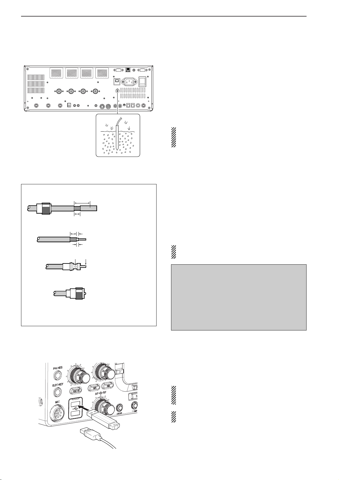
■Grounding To prevent electrical shock, television interference
(TVI), broadcast interference (BCI) and other prob-
lems, ground the transceiver through the GROUND
terminal on the rear panel.
For best results, connect a heavy gauge wire or strap
to a long earth-sunk copper rod. Make the distance be-
tween the [GND] terminal and ground as short as pos-
sible.
RWARNING: NEVERconnect the [GND]
terminal to a gas or electric pipe, since the connec-
tion could cause an explosion or electric shock.
■Antenna connection For radio communications, the antenna is of critical im-
portance, along with output power and receiver sensi-
tivity. Select antenna(s), such as a well-matched 50 Ω
antenna, and feedline. We recommend 1.5:1 or better
of Voltage Standing Wave Ratio (VSWR) for your de-
sired band. Of course, the transmission line should be
a coaxial cable.
When using 1 antenna, use the [ANT1] connector.
CAUTION: Protect your transceiver from lightning
by using a lightning arrestor.
■USB-Memory connection (USB-Memory: Not supplied by Icom)
Connect the USB-Memory* to the USB connector.
•Unmount operation is necessary before removing the USB-
Memory* (p.12-25).
Make sure to connect the USB-Memory correctly.
NEVER connect or remove the USB-Memory when
the read/write indicator lights or blinks.
AUSB keyboard* or USB hub* can also be con-
nected to the USB connector.
*: USB-Memory, USB keyboard or USB hub is not supplied
by Icom.
Antenna SWR
Each antenna is tuned for a specified frequency
range and SWR may be increased out-of-range.
When the SWR is higher than approx. 2.0:1, the
transceiver’s power drops to protect the final transis-
tors. In this case, an antenna tuner is useful to match
the transceiver and antenna. Low SWR allows full
power for transmitting. The IC-7700 has an SWR
meter to monitor the antenna SWR continuously.
PL-259 CONNECTOR INSTALLATION EXAMPLE
30 mm ≈9⁄8in 10 mm ≈3⁄8in 1–2 mm ≈1⁄16 in
30 mm
10 mm (soft solder)
10 mm
1–2 mm
solder solder
Soft
solder
Coupling ring
Slide the coupling ring
down. Strip the cable
jacket and in the braid.
Slide the connector
body on and solder it.
Screw the coupling
ring onto the
connector body.
Strip the cable as
shown at left. Tin the
center conductor.
q
w
e
r
or

2-5
2
INSTALLATION AND CONNECTIONS
■Required connections
DDFront panel
POWER
TUNER
TIMER
VOX
SSB CW
RTTY/PS
VOX GAINMONI GAINCOMPDRIVE
BK-IN MONITOR
TRANSMIT
MIC
ELEC-KEY
PHONES
AF RF
MIC RF
PWR
KEY
SPEED
DELAY
F-1 F-2 F-3
TX RX
AGC VR
NR NB
i7700
HF/50MHz TRANSCEIVER
AGC SQL NR NB
Microphones (p. 2-10)
CW key
A straight or bug key can be used when
the internal electronic keyer is turned
OFF in keyer set mode. (p. 4-12)
Optional
SM-20 Optional
HM-36
DDRear panel
ALC
ADJ
ALCRELAY CW KEY
EXT
KEYPAD
METER
DC OUT
15V
MAX1A
REF I/O
10MHz
-
10dBm
INOUT
REMOTE RS
-
232C
EXT
-
DISPLAY
RX ANT
INOUT
S/P DIF
12
ACC
EXT
-
SP
ANT 1 ANT 2 ANT 3 ANT 4 GND
AC
15A
I
X
-
VERTER
Antenna 1, 2, 3, 4 (p. 2-4) Straight key
Ground
(p. 2-4) Use the heaviest gauge
wire or strap available and
make the connection as
short as possible.
Grounding prevents elec-
trical shocks, TVI and oth-
er problems.
AC outlet
RWARNING:
Use the supplied
AC power cable
only.
NOTE: Attach the sup-
plied antenna connec-
tor cap when no anten-
na or external equip-
ment is connected.
[Example]: ANT1 for 1.8—18 MHz bands, ANT 2 for 21—28 MHz bands
ANT3 for 50 MHz band, ANT 4 for receive antenna.

2-6
2INSTALLATION AND CONNECTIONS
■Advanced connections
DDFront panel
ALC
ADJ
ALCRELAY CW KEY
EXT
KEYPAD
METER
DC OUT
15V
MAX1A
REF I/O
10MHz
-
10dBm
INOUT
REMOTE RS
-
232C
EXT
-
DISPLAY
RX ANT
INOUT
S/P DIF
12
ACC
EXT
-
SP
ANT 1 ANT 2 ANT 3 ANT 4 GND
AC
15A
I
X
-
VERTER
RX ANT IN/OUT
Connects an external
preamp or lowpass filter.
RX ANT IN/OUT must be
activated in the antenna
set screen (p.10-5).
ACC sockets
(pgs. 2-9, 2-11)
Antenna 1, 2, 3, 4 (p. 2-8)
Connects a linear amplifier,
antenna selector, etc.
[X-VERTER]
Connects a transverter
for V/UHF band use.
[RELAY], [ALC] (p. 2-8)
Used for connecting a
non-Icom linear amplifier.
External speaker (p. 15-4)
SP-20
(option)
[REMOTE], [RS-232C] (p. 14-2)
Used for computer control and transceive operation.
The optional CT-17 is required when connecting a
PC to [REMOTE].
POWER
TUNER
TIMER
VOX
SSB CW
RTTY/PSK
VOX GAINMONI GAINCOMPDRIVE
BK-IN MONITOR
TRANSMIT
MIC
ELEC-KEY
PHONES
AF RF
MIC RF
PWR
KEY
SPEED
DELAY
F-1 F-2 F-3
TX RX
AGC VR
NR NB
i7700
HF/50MHz TRANSCEIVER
AGC SQL NR NB
MIC
Headphones
USB-Memory
The AFSK modulation signal can also
be input to [MIC].
Keyboard
Connects an USB type PC key-
board directly for RTTY/PSK31 op-
eration, as well as other text edit op-
erations.
DDRear panel— 1

2-7
2
INSTALLATION AND CONNECTIONS
DDRear panel— 2
ALC
ADJ
ALCRELAY CW KEY
EXT
KEYPAD
METER
DC OUT
15V
MAX1A
REF I/O
10MHz
-
10dBm
INOUT
REMOTE RS
-
232C
EXT
-
DISPLAY
RX ANT
INOUT
S/P DIF
12
ACC
EXT
-
SP
ANT 1 ANT 2 ANT 3 ANT 4 GND
AC
15A
I
X
-
VERTER
External Display
Connects a PC-style
monitor display (at least
800×600 resolution).
Video output signal can
be turned ON and OFF
in set mode (p. 12-11)
[DC OUT]
Outputs regulated 14 V
(approx.) DC for external
equipment power supply.
(max. 1 A capacity)
External keypad
Connects an external keypad for direct voice memory
and memory keyer controls.
Connects a PC for
audio signal data
(48 kHz, 16-bit)
input/output.
[S/P DIF IN/OUT]
Connects a PC
via a LAN for the
CPU firmware
update.
Ethernet connector (p. 16-6)
1.5 kΩ
±5% 1.5 kΩ
±5% 2.2 kΩ
±5% 4.7 kΩ
±5%
S1
(T1/M1) S2
(T2/M2) S3
(T3/M3) S4
(T4/M4)
EXTERNAL KEYPAD
3.5 (d) mm; 1⁄8″plug
Mute switch: Mutes both transmission and
reception when switched ON during trans-
ceive operation, etc.
[METER]
Connects an external meter, etc.
3.5 (d) mm; 1⁄8″plug

DDConnecting a non-Icom linear amplifier RWARNING:
Set the transceiver output power and linear ampli-
fierALC output level after referring to the linear am-
plifier instruction manual.
The ALC input level must be in the range 0 V to
–4 V. The transceiver does not accept positive volt-
age. Non-matched ALC and RF power settings
could overheat or damage the linear amplifier.
The maximum signal level of [RELAY] jack is
16 V/0.5 A DC with initial setting, and 250 V/200 mA
with “MOSFET” setting (see p. 12-8 for details). Use
an external relay unit if your non-Icom linear ampli-
fier requires control voltage and/or current greater
than specified.
■Linear amplifier connections
DDConnecting the IC-PW1/EURO
2-8
2INSTALLATION AND CONNECTIONS
RF OUTPUT RF INPUT
SEND
ALC
50 Ω
coaxial cable
TransceiverANT1
ALC
RELAY
To an
antenna
Non-Icom linear amplifier
To an
antenna
ACC-1
ANT
ANT2
ANT1
ACC 2
INPUT1
INPUT2
REMOTE
EXCITER
11&2
GND
GND
IC-PW1/EURO
AC outlet
(Non-European versions: 100–120/220–240 V
European version : 230 V)
Ground
Transceiver
REMOTE
Remote control cable (supplied with the IC-PW1/EURO)
ACC cable (supplied with the IC-PW1/EURO)
Be sure to connect the cable
to the 7-pin ACC 2 jack.
Coaxial cable
(supplied with the
IC-PW1/EURO)
Coaxial cable*
*Optional
Connect
[INPUT2]
if necessary

2-9
2
INSTALLATION AND CONNECTIONS
■Transverter jack information When 2 to 13.8 V is applied to pin 6 of [ACC 2], the [X-
VERTER] connector is activated for transverter oper-
ation and the antenna connectors do not receive or
transmit any signals.
While receiving, [X-VERTER] connector can be acti-
vated as an input terminal from an external transverter.
While transmitting, the [X-VERTER] connector outputs
signals of the displayed frequency at –20 dBm (22 mV)
as signals for the external transverter.
■FSK and AFSK (SSTV) connections
To connect a TNC or scan converter, etc., refer to the
diagram below.
Connect to serial port, parallel
port, speaker jack, microphone
jack and line IN/OUT jack, etc.
See the instruction manual of
the application for details.
DAFSK operation
• When connecting to [ACC 1]
• When connecting to [MIC]
• When using a PC application
• When using a TNC
PC
RS-232C
TNC or scan converter
PTT
Audio output
AF input
GND
AFSK output
AF input
GND
PTT*
SQL input†
*When using the VOX function, no need to connect. Refer to the instruction
manual of the external equipment (TNC, etc.).
†When connecting the squelch line, consult the necessary manual (TNC, etc.).
q
w
ert
y
u
i
1
2
3
45
67
8
z
z
x
x
c
c
v
v*
z
x
c
v
z
x
c
v
b
b
n†
n†
b
n†
Rear panel view
Rear panel view
PC
RS-232C
TNC or scan converter
Connect to serial port, parallel
port, speaker jack, microphone
jack and line IN/OUT jack, etc.
See the instruction manual of the
application for details.
DFSK operation— when connecting to [ACC 1]
• When using a PC application
• When using a TNC
1
2
3
45
67
8
Rear panel view
Rear panel view
RTTY
GND
AF
SEND
RTTY
GND
AF
SEND
RTTY OUTPUT
GND
AUDIO INPUT
PTT
RTTY OUTPUT
GND
AUDIO INPUT
PTT
1
2
3
45
67
8
Transverter connector

■Microphone connector information
(Front panel view)
CAUTION: DO NOT short pin 2 to ground as this
can damage the internal 8 V regulator.
NOTE: DC voltage is applied to pin 1 for micro-
phone operation. Use caution when using a non-
Icom microphone.
■Microphones (options)
qUP/DOWN SWITCHES [UP]/[DN]
Change the selected readout frequency or memory
channel.
•Continuous pushing changes the frequency or memory
channel number continuously.
•While pushing [XFC], the transmit readout frequency can
be controlled while in split frequency operation.
•The [UP]/[DN] switch can simulate a key paddle. Preset
in the keyer set mode. (p. 4-12)
wPTT SWITCH
Push and hold to transmit; release to receive.
ePTT LOCK SWITCH (available for SM-20 only)
Push to toggle between transmit and receive.
2-10
2INSTALLATION AND CONNECTIONS
[MIC] FUNCTION DESCRIPTION
Pin No.
w+8 V DC output Max. 10 mA
eFrequency up Ground
Frequency down Ground through 470 Ω
rSquelch open “Low” level
Squelch closed “High” level
yGND (PTT ground)
tPTT
rSquelch switch
qMicrophone input
w+8 V DC output
eFrequency up/down
uGND
(Microphone ground)
iAF output (varies with [AF])
DSM-20
DHM-36
q
w
q
w
e

2-11
2
INSTALLATION AND CONNECTIONS
■Accessory connector information
ACC 2
PIN No.
NAME DESCRIPTION SPECIFICATIONS
ACC 1
PIN No.
NAME DESCRIPTION SPECIFICATIONS
NOTE: If the CW side tone level limit or beep level
limit is in use, the CW side tone or beep tone de-
creases from the fixed level when the [AF] control is
rotated above a specified level. (p. 12-6)
1
2
3
45
67
8
“High” level : More than 2.4 V
1RTTY Controls RTTY keying “Low” level : Less than 0.6 V
Output current : Less than 2 mA
2GND Connects to ground. Connected in parallel with ACC 2 pin 2.
Input/output pin. Ground level : –0.5 V to 0.8 V
3SEND Goes to ground when transmitting. Output current : Less than 20 mA
When grounded, transmits. Input current (Tx) : Less than 200 mA
Connected in parallel with ACC 2 pin 3.
4MOD Modulator input. Input impedance : 10 kΩ
Connects to a modulator. Input level : Approx. 100 mV rms
AF detector output. Output impedance : 4.7 kΩ
5AFFixed, regardless of [AF] position Output level : 100–300 mV rms
in default settings. (see notes below)
6SQLS Squelch output. SQL open : Less than 0.3 V/5 mA
Goes to ground when squelch opens.
SQL closed : More than 6.0 V/100 µA
713.8 V 13.8 V output when power is ON. Output current : Max. 1 A
Connected in parallel with ACC 2 pin 7.
Control voltage : –4 V to 0 V
8ALC ALC voltage input. Input impedance : More than 10 kΩ
Connected in parallel with ACC 2 pin 5.
18VRegulated 8 V output. Output voltage : 8 V ±0.3 V
Output current : Less than 10 mA
2GND Same as ACC 1 pin 2.
3SEND Same as ACC 1 pin 3.
4BAND Band voltage output. Output voltage : 0 to 8.0 V
(Varies with amateur band)
5ALC Same as ACC 1 pin 8.
6TRV
Activates [X-VERTER] input/output Input impedance : More than 10 kΩ
when “HIGH” voltage is applied. Input voltage : 2 to 13.8 V
7
13.8 V
Same as ACC 1 pin 7.
1
2
3
45
67
Other manuals for IC-7700
7
Table of contents
Other Icom Transceiver manuals

Icom
Icom IC-2330A User manual

Icom
Icom IC-T2H User manual

Icom
Icom iF4029SDR User manual

Icom
Icom IC-271A User manual

Icom
Icom IC-F3160 SERIES User manual

Icom
Icom IC-F29SR User manual

Icom
Icom IC-F5020 Series User manual

Icom
Icom IC-M88 Instruction Manual

Icom
Icom IC-M7 User manual

Icom
Icom IC-GW1 User manual