ICON TECH LINE: 951.689.ICON www.iconvehicledynamics.com
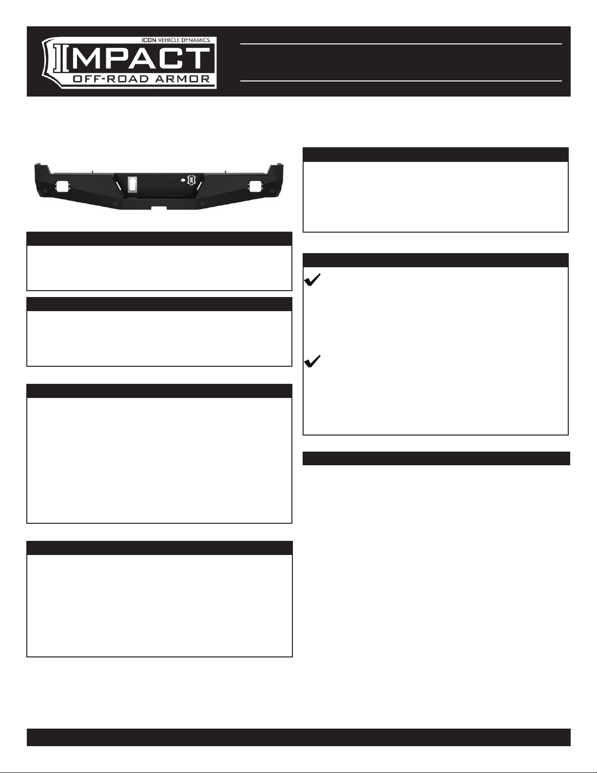
17-UP FSD PRO SERIES REAR
BUMPER
INSTALLATION INSTRUCTIONS
DOCUMENT: INST_66201_REVA • UPDATED: FEB 2023
APPLICATION
These installation instructions apply to the following
products:
66201 17-UP FSD PRO SERIES REAR BUMPER
COMPONENTS INCLUDED
(1) 17-UP FSD REAR BUMPER
(1) 17-UP FSD REAR BUMPER FRAME BRKT PASS
(1) 17-UP FSD REAR BUMPER FRAME BRKT DRVR
(1) 17-UP FSD REAR BUMPER HARDWARE KIT
HARDWARE INCLUDED
(1) TRAILER CONNECTOR PLATE
(2) BUMPER LICENSE PLATE RETAINER
(4) 10-32 X .500 BHCS 18-8 RAW
(1) BUMPER SENSOR MOUNT (FOUR PACK)
(4) #10 SAE FLAT WASHER GR2 CZINC
(4) 10-32 NYLOCK NUT CZINC
(8) 1/2-13 X 1.000 HHCS GR8 YZINC
(8) 1/2 SAE FLAT WASHER GR8 YZINC
(6) CABLE TIE HOLDER ADHESIVE MOUNT
(6) 5-1/2 X 0.14 NYLON CABLE TIE BLACK
TOOLS REQUIRED
• Ratchet and extensions
• Body panel clip removal tool
• Flat head screwdriver
• 15mm socket/wrench
• 21mm socket/wrench
• 1/8” hex key
• 3/8” socket/wrench
• 3/4” socket/wrench
TECH NOTES
NOTE: These installation instructions are based on
a clean installation on to a stock vehicle. Previously
modified vehicles may require additional steps.
NOTE: Install time: 1.5-2 hours - Additional time may
be needed for light installation.
IMPORTANT NOTICES - PLEASE READ FIRST
READ ALL INSTRUCTIONS THOROUGHLY
FROM START TO FINISH BEFORE BEGINNING
INSTALLATION! IF THESE INSTRUCTIONS ARE
NOT PROPERLY FOLLOWED SEVERE FRAME,
SUSPENSION OR TIRE DAMAGE MAY RESULT TO
THE VEHICLE!
ICON VEHICLE DYNAMICS RECOMMENDS
ALL INSTALLATION TO BE PERFORMED BY A
PROFESSIONAL SHOP/SERVICE TECHNICIAN.
PRODUCT FAILURE CAUSED BY IMPROPER
INSTALLATION WILL NOT BE COVERED UNDER
ICON’S WARRANTY POLICY.
INSTALLATION INSTRUCTIONS
1. Ensure the vehicle is placed on a flat, level surface
with the transmission in PARK (or first gear for
vehicles equipped with a manual transmission),
the tires chocked, and the emergency brake ON.
Wear safety glasses from this point forward.
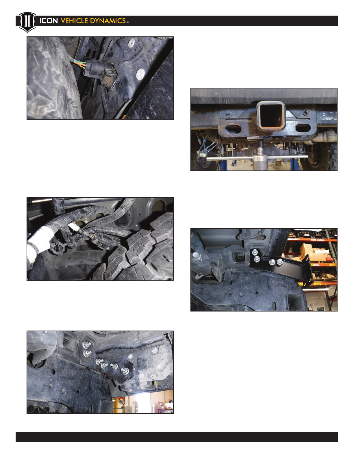
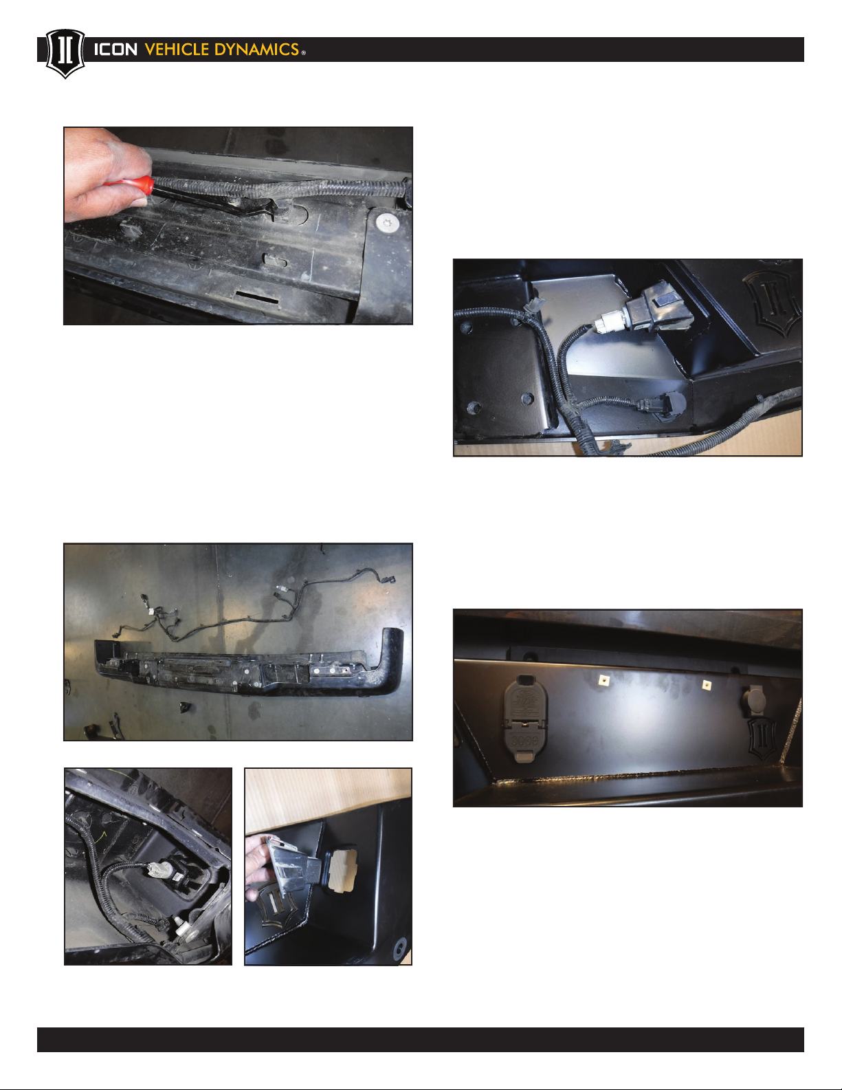
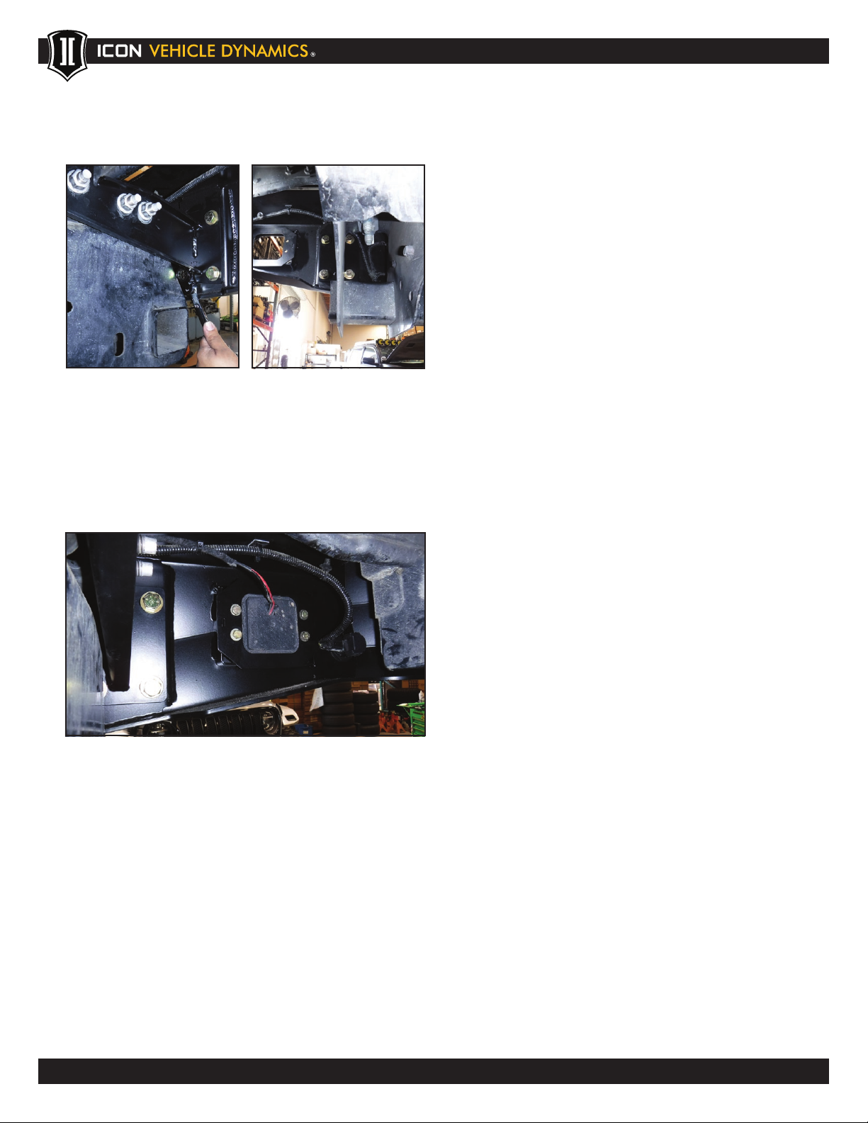
2. Starting from the underside of the rear bumper,
remove the trailer plug harness by pressing the
push tab on the bottom of the plug and pull out.
Thank you for purchasing this ICON Vehicle Dynamics product. Please read through this entire document before proceeding with
installation. If you are not confident in your mechanical skills, please seek the help of a professional to perform the installation. Check your
packages immediately upon arrival to ensure that everything listed is included, and to check for damage during shipping. If anything is
missing or damaged, or if you need technical assistance with any aspect of this installation, call (951) 689-ICON as soon as possible.