Iconic VF1 User manual

VF1
Iconic Vacuum Forming Machine
Instruction Manual

2
CONTENTS Page
1 - INTRODUCTION 03
2 - TECHNICAL SPECIFICATIONS 03
3 - PACKAGING CONTENTS 03
4 - INSTALLATION INSTRUCTIONS 04
5 - INSTRUCTIONS FOR USE 05
6 - SAFETY AND FUNCTIONALITY PRECAUTIONS 11
7 - MAINTENANCE AND CLEANING 12
8 - SPECIAL STORAGE CONDITIONS 12
9 - TROUBLESHOOTING 13
10 - WARRANTY TERMS & SERVICING 14
11 - AUTHORIZED ASSISTANCE 14

3
VF1
1 - INTRODUCTION
Thank you for purchasing the Iconic VF1 vacuum forming machine. Please read the contents of this manual to ensure
safe and trouble free operation whilst achieving the highest quality results.
The vacuum forming procedure involves heating vacuum forming material for a set length of time or to achieve a
specic amount of sag in the blank before vacuum forming the material. Because of this process, the Iconic VF1
machine must not be left unattended whilst in operation.
2 - TECHNICAL SPECIFICATIONS
Power supply: Unique voltage 50 Hz / 230V
Consumption power: 925W average
Heating power: 450W Motor Power: 1400W
Plate Dimensions:
Thickness up to 6mm
Round Plate: From Ø120 to Ø134mm
Square Plate: From 120x120mm to 130x130mm
Dimensions: (WxDxH) 180 x 230 x 290 mm (w/o packaging) 200 x 250 x 300 mm (w/ packaging)
Weight: 4.500 kg (w/o packaging)
5.235 kg (w/ packaging)
Pollution Degree: 2 Protection
Degree: IPX1 (Protected against splatter)
Noise Level: Motor 80/90 dB to 0.50m
3 - PACKAGING CONTENTS
01 - Power cable 01 unit
02 - Glass beads 250g
03 - Allen wrench 4mm 01 unit
04 - Plates display 01 unit
05 - Model holder 01 unit
06 - Instruction manual 01 unit
07 - Iconic VF1 230V 01 unit
08 - Vacuum activating handles 02 unit
09 - Heating unit handle 01 unit
10 - Rotary ring handle 01 unit
01
02
03
05
06
07
08
09
10

4
4 - INSTALLATION INSTRUCTIONS
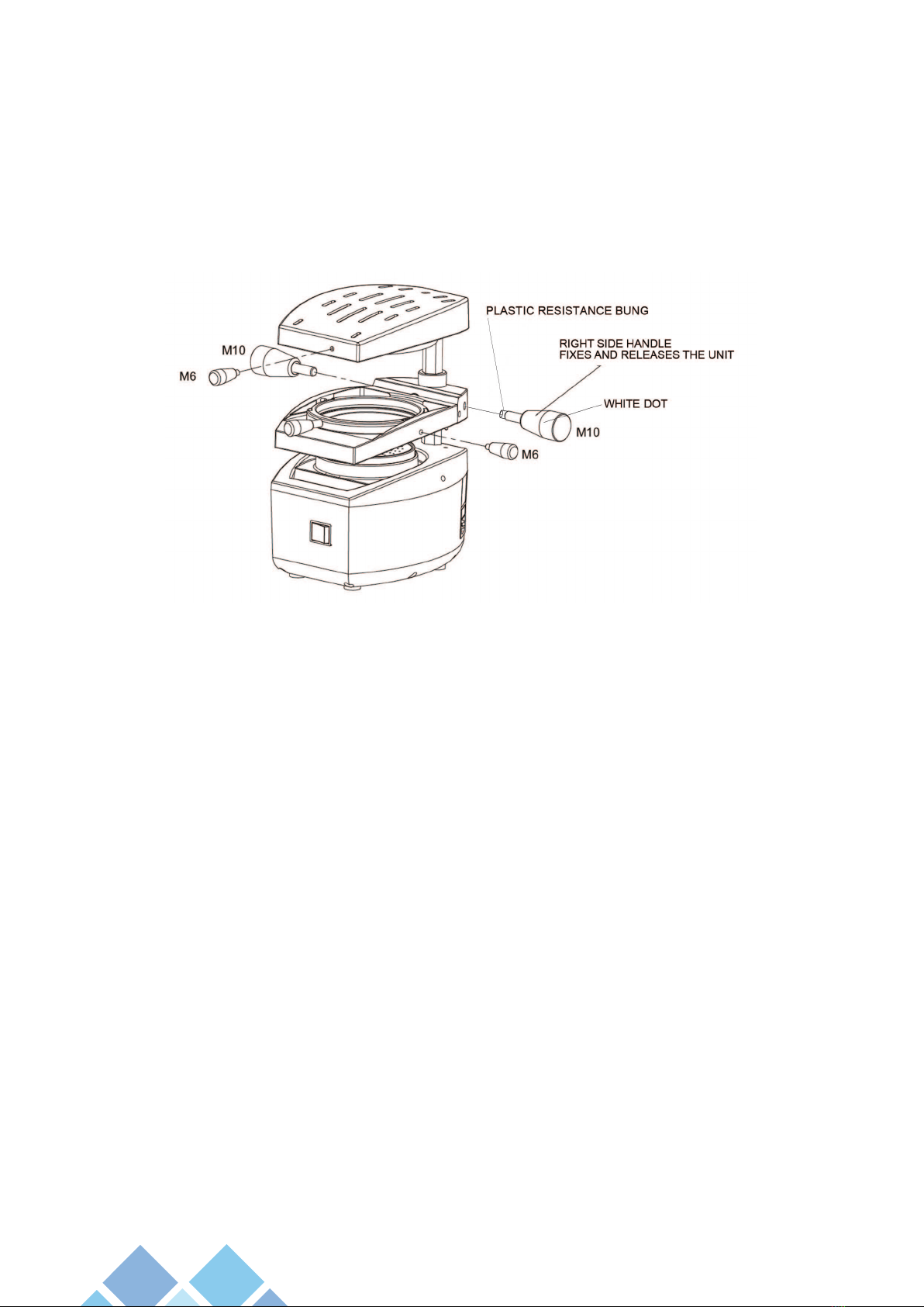
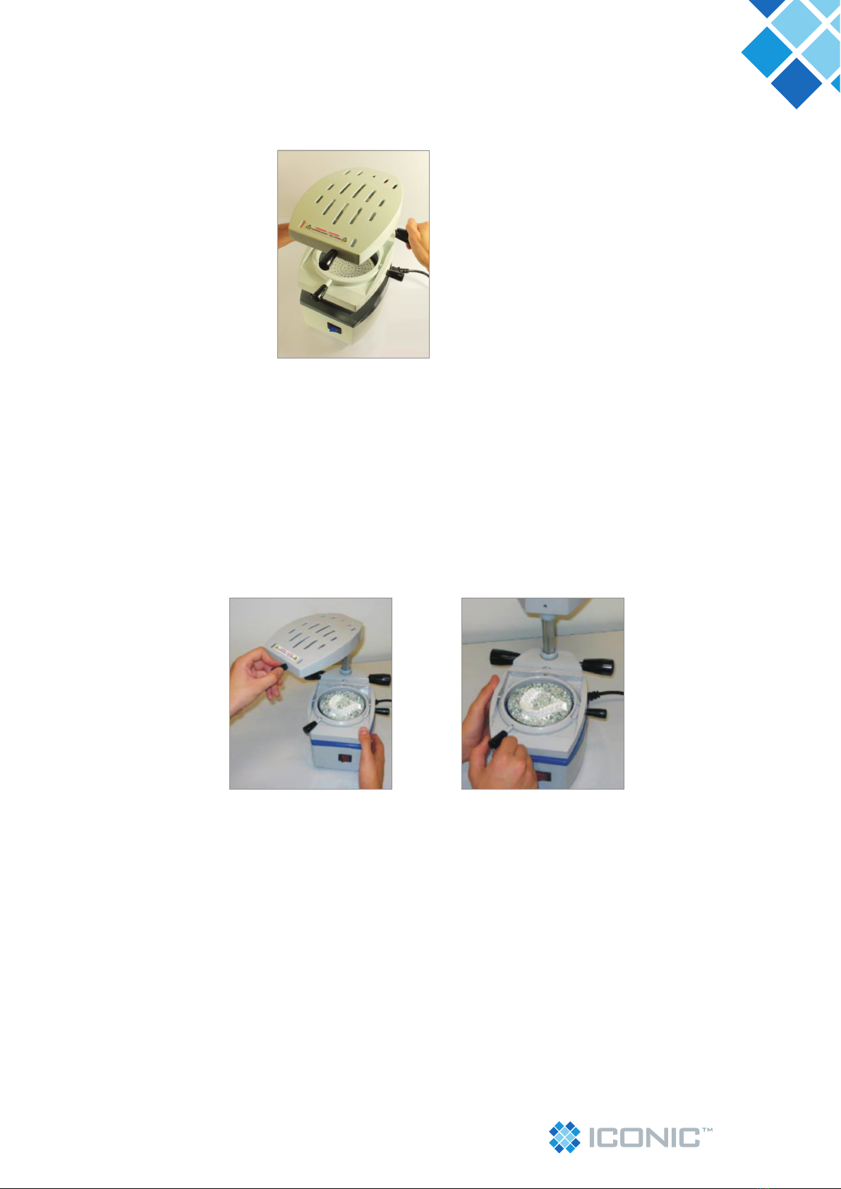
• Before the installation of the machine, mount the handles packed separately inside the packaging. These must be
mounted in the plasticizer before its installation, as shown in the illustrative drawing below;
• There are two (2) identical shorter M6 thread handles, one for the heating unit and one for the rotary ring and two
(2) longer vacuum driving M10 thread handles.
• Mount the handles according to drawing below, screwing them clockwise until you feel resistance of the thread end;
• Important: The right vacuum driving handle also has the function to x and release the plate setting unit, therefore
it must be threaded until a slight resistance of the thread end is felt and then release it half turn in the counter-
clockwise direction.
Note: Except for the right vacuum driving handle, the handles cannot be loose and must be tightened manually only,
do not use any type of tool to install them.
• The machine must be installed in a ventilated area, free from moisture and excessive heat and placed on a table or
at bench. Do not build in and do not leave any material between the supporting base and the machine bottom so
that this area can be free to allow air out and refrigerate the motor;
• Keep the machine away from heat sources or liquids (approximately 1 metre);
• It is advisable to install a bipolar protection device (bipolar circuit breaker) in the electric network where the
machine will be installed, for phase disconnection in case of possible failures;
• Do not use extension plugs or any other type of similar connection to run the machine in the same outlet where
other equipment is installed;
• Important conditions for the ideal operation of the machine:
• Use the machine in a sheltered area;
• Room temperature between 5°C and 40°C;
• Maximum relative humidity 80%;
• Maximum altitude 2000m;
• Voltage variations allowed for power supply: ±10% of the rated voltage.
Attention:
If the machine is not used in accordance with the specications described in this chapter, the safety and functionality of
the product may be put at risk.

5
VF1
5 - INSTRUCTIONS FOR USE
Iconic VF1 provides two (2) processes of vacuum forming: Conventional and Rotary.
For the operational process follow the instructions below guiding from the numbers in Figures 1 and 2.
Figure 01 Figure 02
FIGURE 01
01- Heating unit handle
02- Heating unit
03- Vacuum activation handles
04- Blank fastening unit (Larger ring + Pivot)
05- Upright
06- Model holder with at functions and cup
07- Vacuum chamber
08- General switch and for heating
09- Shorter ring handle
5.1 - Conventional plastic forming process:
5.1.1 - To start the vacuum forming process, the machine must be with the power cord connected to the power supply
network and the general key (08) off.
5.1.2 - The vacuum activation handle (right side) (03), besides the activation function, has also the function of xing and
releasing the blank fastening unit (4). To release it, make a half turn in a counter-clockwise direction. To fasten, tighten
to the end of the thread in a clockwise direction.
With the unit released, always with both hands, one on each handle (03), raise the blank fastening unit (04) to near the
heating unit (02), turn the right handle (03) in a clockwise direction xing the unit (04) in the correct position (photo 02).
FIGURE 02
10 - Rotary lock screw
11 - Lock side pins
12 - Longer ring

6
5.1.3 - With the help of handle (01), rotate the heating unit (02), 180º to the left to facilitate the manipulation job with
the models and model holders and to install the blanks (photos 03 and 04).
5.1.4 - Put the model(s) in the model holders (06) and then insert the model(s) in the vacuum chamber (07).
The model holder can be positioned in two (2) ways:
5.1.4.1 - Cup position: Facilitates the removal of blanks, mainly incases when the model shows retentions or when
using rigid blanks and/or thicknesses higher or lower than 1.0 mm.
To use the model holder in this position, put the model on the cup side of the Model Holder (06) and ll with glass beads
covering the retentive surface to the desired limit. Then introduce the assembly in the vacuum chamber (photos 05, 06
and 07).
Photo 03 Photo 04
Photo 01 Photo 02
Photo 05 Photo 06 Photo 07

7
VF1
5.1.4.2 - Flat position:
Allows making a copy of the whole extension of the model. For better results, cut the model eliminating its retentions
and obtaining a at base. Do not use a very high model in this process, because there will be a higher distortion of the
blank.
To use the at side of the Model Holder (06), introduce the model holder in the machine vacuum chamber with the head
turned downwards. Then position the model on the model holder (photo 08 and 09 and 10).
Important: Make sure the vacuum chamber (07) is clean and free from residues for the perfect sealing of
the model holder.
5.1.5 - For the positioning of the blank, turn the smaller ring cable (09) counterclockwise to the right, to release the
smaller ring and allow the insertion of the blank (photo 11).
Photo 11
Photo 08 Photo 09 Photo 10

8
5.1.6 - Insert the blank for moulding from the front side of the xing unit observing a small access slope and introducing
it under the two side pins ( photo 11) (photo 12).
5.1.7 - Insert the smaller ring into the xing unit on the blank observing the two side pin guides (11) and turn it to the
left clockwise direction using the handle (09) locking the blank (photo 13).
Attention:
It is important to always maintain a rm grip on the blank xation unit (04) while the blank is being put in place. (Photo
13).
5.1.8 - Put the heating unit (02) back to the central position aligned with the motor cabinet and actuate the general key
(08), starting the heating process. The red light on the general switch will go on (photos 14 and 15).
5.1.8.1 - Ideal plastic forming point: Due to the existence of several types of vacuum form material (different materials
and thicknesses), the ideal plastic forming point is identied by changes in the plate and not by time. In view of this, it is
the responsibility of each blank manufacturer to provide instructions of use with their material.
In general, the ideal vacuum point is observed by the sagging of the plate from 10 to 20mm, as shown in the drawing
below.
Photo 13Photo 12
Photo 15Photo 14
10 to 20mm

9
VF1
5.1.9 - Upon reaching the ideal plastic forming point, turn the vacuum activation handle right side (03), half turn counter-
clockwise direction to release the blank xation unit (04), lower the whole of the xation unit set of the blanks with both
hands (one at each handle), causing the xation unit frame of the blank to close to the vacuum chamber (photo 16).
5.1.10 - Turn the heating unit 90º minimum clockwise direction by the heating unit handle (01) right after the vacuum
activation, to avoid accidents and likely blisters on the plate (photo 17). Leave the vacuum system (motor) actuating
until you are sure the conformation process by the vacuum is completed (10 to 20 seconds depending on the plate
thickness).
Care: Do not leave the motor on for more than one (1) minute when moulding the blank is on the vacuum chamber to
avoid overheating, since the motor is air cooled.
5.1.11 - Turn off the General Switch (08) and leave the model cooling down for about 60 seconds.
5.1.12 - Loosen the plate Lock turning the handle (9) to the right counter-clockwise direction, remove the smaller
ring (12) and then the model.
Attention:
To remove the model and nish the blank, cut off the excess of material with a pair of scissors, or a tricutter, depending
on the stiffness and thickness of the blank.
For stiffer blanks or above 1.0mm thick, we strongly recommend the use of the Cup Model Holder when vacuum
forming, as previously mentioned. The nal nish of the edges can be made with polypropylene non woven polishing
disks.
5.2 – Plastic forming process using the rotary system.
To make use of the rotary plastic forming system that allows the heating on both faces of the blank, follow the
instructions below, guiding by the number of the main components of the machine in Figure 02 of this manual.
The machine leaves the factory with the blank xation unit locked by the lock screw of the rotary (10), to avoid
accidental rotation when the plastic forming process is conventional (heating only one face). To use the rotary system
it is necessary to loosen the lock screw (10) by using a 4mm Allen key supplied with the product (it is not necessary to
remove the screw, only loosen it) (photo 19).
Photo 16
Photo 18Photo 17

10
Attention:
We recommend always keeping the system locked while the machine is used the conventional way, by slightly tightening
the lock screw (10).
When using the rotary system with heating on both faces of the blank, place the model after the whole heating process
of the blank is completed on both faces, since the rotation of the rotary ring may hit the model, damaging it.
5.2.1 - After releasing the rotary system lock, follow the steps according to the conventional vacuum forming described
above to 5.1.8, until this phase one side of the plate is heated.
5.2.2 - To heat the other side of the blank, rotate the heating unit completely (180°) to the left by means of the handle
(01) (photo 20).
Only then rotate the larger ring 180º counter-clockwise using its respective handle (photo 21) until you hear a click, thus
exposing the other side of the plate upwards (photo 22 and 23), return the heating unit (02) to the central position and
wait until the face of the blank is heated.
Photo 20
Photo 19
Photo 21 Photo 22 Photo 23

11
VF1
5.2.3 - Repeat item 5.2.2, now rotate the larger ring clockwise to the return the xing system (04) to the normal position
and the plate to the initial position. Leave heating for a few more seconds the same side of the plate that initiated the
process.
5.2.4 - After the heating process is complete, follow the steps of the conventional process from item 5.1.9, until the
process is nished.
Attention:
Never lower the plate xation unit set (04) when the larger ring is rotated 180º counter-clockwise direction, photo 24.
6 - SAFETY AND FUNCTIONALITY PRECAUTIONS
6.1 - A very porous plaster should be used since the air will pass through the model to provide a more efcient vacuum.
6.2 - Trim the model to avoid big deformations of the plate (20mm maximum, or use cup model holder and glass beads).
6.3 - When working with the at part of the model holder leave the plaster model base at to stop the blank from
penetrating the gaps between the plaster model and the model holder.
6.4 - The heating on both faces of the blank is ideal for two different types of materials and for traditional
blanks with thickness higher than or equal to 3mm.
6.4.1 - The heating system of both faces of the blanks must follow the heating process according to the characteristics
of the materials used in the manufacturing of the blanks. This information should be obtained from the blank
manufacturer.
6.4.2.1 - For traditional blank thickness equal or higher than 3mm we recommend heating in two (2) phases. First the
side of the blank that will stay in contact with the model (internal side of the blank). To do that, rotate the blank xation
unit (04) directing this face to the heating unit (02). After this pre-heating, rotate the blank xation unit (04) to the
original position to heat the external side of the moulder.
6.4.2.2 - For double strip blanks* that have a soft material face of low softening temperature and the other face of a
stiff material of high softening temperature, we recommend heating in three (3) phases initiating the heating from the
stiffer face, then from the softer or soft face and nally the stiffer face again until the plastic point according to item
5.1.8.1, this way the double strip blank* should be mounted on the machine with the stiffer face upwards to the heating
unit direction and, consequently, the soft face will conform the model.
6.4.3 - Due to the diversity of blanks and jobs that can be done, we suggest a careful previous analysis of the process
before starting each job .
Note*: Double Strip are blanks made from two (2) different types of materials.
Example: Blanks with one stiff face and the other soft.
Photo 24

12
7 - MAINTENANCE AND CLEANING
Always keep the Iconic VF1 clean and protected from moisture, specially the resistance in the heating unit.
To clean the cabinet, use only water, wet cloth and use neutral detergent. The heating element is a component that
requires some attention, it should not receive moisture while heated and should not be touched by tools or metallic
objects.
If you need to replace the element, it should be done by authorised personnel.
In case the power cord is damaged, it should be replaced by another with the same characteristics and certications.
The machine upright does not require lubrication, keep it always clean and free from dust or residues.
7.1 - Fuse Replacement
7.1.1 Disconnect the power supply cord from the outlet and input connector before replacing the fuse.
7.1.2 Insert a small screwdriver in the hole in the upper part of the fuse-holder cover located in the input connector (AC)
forcing it out until the assembly gets loose.
7.1.3 Pull the fuse-holder assembly out to the end and watch for the existence of two (2) fuses tted in the support.
7.1.4 The fuse that is near the internal part of the compartment is the faulty fuse that must be replaced. The other one
(near the compartment cover) is the spare fuse that will be used to replace the faulty fuse.
7.1.5 Insert the assembly with the replaced fuse in the compartment again and press them until is ts completely.
7.1.6 Turn the machine on to check as to the correct functioning. In case the fuse shows problems again, forward the
equipment to the Authorized Service to verify the likely cause of the problem and solve it.
7.1.7 Contact DB Orthodontics for replacement 10Amp fuses.
8 - SPECIAL STORING CONDITIONS
In case the machine needs to stay idle for long periods of time, we recommend to store it in its original packaging in a
dry, airy, free of vibration location and sheltered from sunlight.

13
VF1
9 - TROUBLESHOOTING
Problem Likely cause Solution
The equipment won’t start, general
switch is off.
Machine is powerless.
General switch starts but heating does
not work.
Heating element is burnt. (22). Replace the heating element, call the
Authorized Service.
Heating is normal but motor does not
start.
End-of-course pin (32) with some
imperfection.
Replace or adjust the end-of•course pin
(32).
General switch starts, but heating and
motor don’t.
Internal wiring has problems. Call the Authorized Service.
Weak suction, insufcient vacuum
forming or without dened contour.
Check that the vacuum chamber holes
are free.
Clean holes with 1mm Ø metallic pin.
Verify the type of plaster. Do not use resined plaster.
High model Use the model holder on the cup side or
cut the model away.
Cup type model holder (7) damaged. Replace the model holder (07).
Rotary movement of the plate xation
unit is locked.
Rotary lock screw is tight (Photo 20). Loosen the screw with the Allen wrench
supplied with the equipment (Photo 20).
Rotary movement of the plate xation
unit does not stop at end of course.
Rotary pin (29) misadjusted. Adjust the pin (29) by the screw (27), guide
by the exploded drawing.
Vertical movement on the column of the
plate xation unit is very hard.
Right cable of vacuum actuation (03) tight Loosen the handle half way in a counter-
clockwise direction.
Residues or dirt in upright Turn off the machine and clean the column
with dry cloth by doing vertical movements
with the blank xation unit.
Machine overheated causing excessive
expansion of the sliding elements.
Wait 30 minutes until the machine cools
down and resume work.
Motor cabinet (01) too hot. Machine operating too long Wait 30 minutes until the machine cools
down and resume work.
Motor ventilation blocked Verify if in the space between the support
base and the cabinet bottom there is no
obstruction.
The blank gets loose from the xing unit
at the plasticization.
Insufcient tightening of the blank by the
lock ring (11).
Tighten a little bit more and check the
blank thickness, the machine accepts
blanks of up to 6mm thick.
Plate xation unit will not lock out under
heating unit.
Plastic resistance bung is missing. Undo right side handle (white dot). Replace
missing plastic resistance bung.

14
10 - WARRANTY TERMS AND SERVICING
DB Orthodontics Limited gives one (1) year warranty (from date of purchase) to Iconic VF1. This warranty comprises any
and all manufacturing defect, provided by repairing the product and limited to the following requirements:
a) That the product was correctly used, according to the instructions supplied. We remind that the vacuum former must
be handled, transported and stored carefully. Falls or hits on the equipment will be cause of misuse, leading to loss of
warranty.
b) The complaint be followed by the Purchasing Invoice.
To enjoy this warranty, the consumer should ship the product at his own expenses (freight at the owner’s expenses) to
the following address:
DB Orthodontics Limited
Ryeeld Way
Silsden
West Yorkshire
BD20 0EF
United Kingdom
T: +44 [0] 1535 656999
F: +44 [0] 1535 656969
W: www.dbortho.com
The machine servicing can only be provided by specialised personnel. Any unauthorised maintenance in the machine
will cause loss of warranty. If the machine is sent for servicing, make sure the machine is duly packed to avoid damage
during transportation.
Excluded from this warranty are eventual defects from natural wear of the product as well as damage caused during
transportation to and from the destination. The information in this manual is subject to changes that may be made
without previous notice.
11 - AUTHORISED SERVICE
For your safety, servicing of this product must be provided by authorised personnel/companies.

15
VF1
DB Orthodontics Limited
Ryeeld Way
Silsden
West Yorkshire
BD20 0EF
United Kingdom
T: +44 [0] 1535 656999
F: +44 [0] 1535 656969
W: www.dbortho.com
ISS 3: 150416
Table of contents
Popular Laboratory Equipment manuals by other brands

Agilent Technologies
Agilent Technologies Triple Quadrupole LC/MS user guide

PSC
PSC PowerScan Quick reference guide

Heidolph
Heidolph Intelligent Hei-VAC Control operating instructions

AFi
AFi KATRINA quick start guide

formlabs
formlabs Form Cure L Installation and usage instructions

MELAG
MELAG Vacuklab 41-B user manual