Icotera 86071 User manual

1
Document version: 1.0
Installation of Icotera optical CPEs and FTUs
Installation Guide for Icotera Fibre Termination Units
and optical Customer-Premises Equipment
Published: February 2017
Document version: 1.0

Installation of Icotera optical CPE and FTU
2
Document version: 1.0
Change log
Date
Version
Reason for a change
Author
15/03/2017
1.0
First release available to public.

Installation of Icotera optical CPE and FTU
3
Document version: 1.0
Preface
This installation guide covers all steps necessary to perform physical installation of Icotera CPE, ONT,
and FTU. It shows how to open FTU case when it can be freely manipulated in hands (eg. after
unpacking it) and when it is mounted on the wall. It also shows various installation examples of the FTU.
Supported models
This guide is applicable to the Icotera FTU model that consists of two parts:
Base 86071
Cover 86072
Changes introduced in this variant allowed to introduce the following features:
The whole FTU set consists of only 2 parts
More fibre may be accommodated inside the FTU base (up to 2 meters depending on the fibre
diameter)
10 locations for fibre insertion points
Possibility to use SC/APC adapters
Integrated SCA caps –no risk of losing separate caps
Latches engage and block CPE/ONT on top of the FTU –the use of screw to secure CPE/ONT
is optional
Reworked hooks secure FTU cover and base together after the CPE/ONT is installed –there is
no need to screw FTU cover and base together
No need to drill holes to lead a fibre through FTU walls –pre-cut kerfs simplify making openings
in the FTU cover
Retained functionalities of the previous FTU 86018/86021 model (possibility to use gas-block,
location point for WDM-filter)
Retained compatibility with all Icotera FTU-dedicated CPE/ONT models
Some of the examples in this Guide refer to the 86018/86021 FTU model, but all
presented solutions may also be used with the 86071/86072 model.

Installation of Icotera optical CPE and FTU
4
Document version: 1.0
Safety precautions
In order to ensure the safety of the user and to avoid CPE malfunctions the device must be stored,
installed and serviced in accordance with safety guidelines. This section outlines the basic safety
recommendations for Icotera's optical CPEs.
Always follow these general guidelines when using Icotera CPEs:
Do not open or disassemble the CPE.
Do not expose the product to liquid or moisture.
Do not expose the product to lit candles, cigarettes, open flames etc.
Do not drop, throw, or try to bend the product.
Do not allow children to play with the product, as it contains small parts that could be detached
and create a choking hazard.
Use only original Icotera components and replacement parts. Failure to do so may result in
performance loss, damage to the product, fire, electric shock, or injury. Any unauthorised
modifications also invalidate the warranty.
In order to minimize the risk of electric shock, avoid using the unit during storms and high
lighting activity.
Treat the product with care. Use only a soft, damp cloth to clean the CPE.
Power supply
Be sure to only use the original, certified power supply unit provided with the CPE. Using any
other PSU may result in permanent damage to the equipment and may lead to fire or injury. If
possible, use surge protector outlets to plug in the PSU.
Storage and operation conditions
When not installed, the CPE should be stored in dry environment and always in original packaging. The
device should not be exposed to severe humidity, heat, or cold during storage and transport. When
moving CPE from cold to warm environments, allow it to warm up before powering up, as to prevent
condensation of moisture inside the device and possible damage to circuitry. Environmental conditions
should not exceed the following specification:
Operating temperature: 0 –45°C
Storage temperature: - 20 –85°C
Humidity for storage and operation: 5% –95% (non-condensing)
Installation and allowed connections
Select a safe location for the CPE and make sure it is always freely accessible. Place the CPE on a firm,
flat surface. Avoid bending or coiling the cables too tightly. Do not obstruct the airflow through and
around the device with surrounding objects, as it is essential for proper ventilation and cooling; there
should be an unobstructed space of minimum 15 centimetres around the CPE.
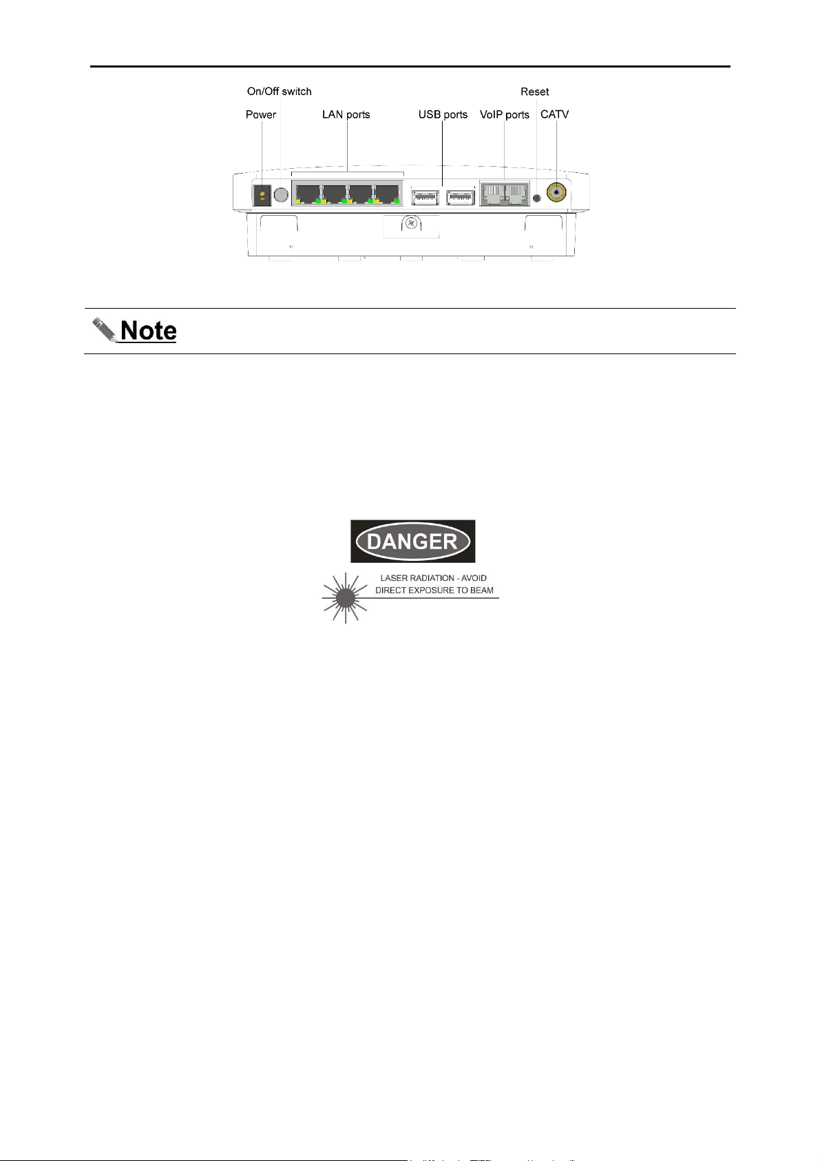
Ensure that only approved telephone handsets are connected to the VoIP ports of the CPE. Only
Ethernet network equipment may be connected to the LAN ports. Damage may occur if network
equipment is plugged into the VoIP ports. This equipment must therefore only be professionally installed
by suitably trained service personnel.
This equipment allows connection only of suitably approved equipment to its ports, the safety status of
which is defined below:
SELV ports: Power, LAN ports, USB ports, CATV port. These ports are classified as SELV
(Safety Extra Low Voltage) in accordance with EN60950-1:2006, and must only be connected to
equipment which similarly complies with the SELV safety classification.
TNV2 ports: Both VoIP ports. These ports, classified as TNV2 (Telecom Network Voltage Type
2) in accordance with EN60950-1:2006, must only be connected to circuits complying with the
requirements therein. Connect only telephone handset equipment which can withstand TNV2
voltages.

Installation of Icotera optical CPE and FTU
5
Document version: 1.0
Figure 1. Example of the front panel of the CPE (your CPE may differ)
Please note that number and type of available ports may vary depending on the
CPE/ONT model.
Fibre optics safety
The Icotera CPE in its optical variant utilizes laser and fibre optic technology. Although the strength of
the light beam transmitted through the fibre is comparably low, caution should be maintained when
handling fibre connectors and cords. When not connected, all optical connectors and sockets must be
protected with dedicated caps. Before handling or reconnecting optical cables, ensure that they are
offline and no signal is transmitted through them.
The device is marked with the following laser warning label:
Figure 2. Laser warning on the CPE

Installation of Icotera optical CPE and FTU
6
Document version: 1.0
Installation set specification
The items listed in the following table are delivered in the CPE package.
Item name
Amount
(pcs)
Item description
Gateway FTU
base
1
A wall-mounted cassette in which the fibres
are spliced and arranged.
Gateway FTU
cover
1
Covers the FTU base, enclosing the spliced
fibres and filters.
Power Supply
Unit
1
Standard power supply unit for the
CPE.
LAN cable
1
2 m long LAN cable to connect CPE
to compatible devices.
The items listed in the following table are not delivered in the CPE package but may be required to
install the CPE, depending on the installation scenario.
Item name
Amount
(pcs)
Item description
Splice protector
1 or 2
The number of required items depends on
the amount of provided services. If the CATV
service is not provided, only one item is
needed; otherwise, 2 items are needed. The
diameter of the protector should be 2.5 mm
and its length should measure from 35 to 55
mm.
SC/UPC pigtail
1
Used for data connection purposes.
SC/APC pigtail
(optional)
1
Used for CATV connection purposes and for
PON CPEs. The endface of the APC
connector should be polished at an 8-
degrees angle.
Cable tie
1 or 2
Used to fix the fibre cable/pipe to the holders.
The amount of required items depends on
the installation type chosen. Cable tie should

Installation of Icotera optical CPE and FTU
7
Document version: 1.0
not be wider than 5 mm, thicker than 2.5 mm,
and longer 150 mm (it can be trimmed if it is
too long).
Wall plug
3 - 5
Used together with the screw to mount the
FTU on the wall.
M3.5x34 screw
3 - 5
Used together with the wall plug to mount the
FTU on the wall.
Gas block
connector - type 1
(optional)
1
Used for gas sealing when the installation
type is blowing air pipe based.
Gas block
connector - type 2
(optional)
1
Used for gas sealing when the installation
type is blowing air pipe based.
WDM Filter
1
Demultiplexes incoming signal to separate
CATV and data fibres.

Installation of Icotera optical CPE and FTU
8
Document version: 1.0
Mounting location recommendations
When considering the layout of fibre optics on your premises and the location of the CPE, it is important
to consider a number of factors:
Unobstructed access to the device for maintenance and possible modifications.
The device should be mounted in such a way as to allow customer equipment cables to be
connected freely, without becoming bent or tangled. Tension in the cables may cause damage to
CPE ports and disrupt connections. Removing the CPE from the FTU after it is installed will also
require leaving space above the device, due to the nature of the sliding mounting mechanism.
Free airflow ensuring proper working conditions for the CPE.
The Icotera's CPE has ample ventilation openings on the sides and top of the CPE. It is important to
remember however, that free airflow must be maintained in the area surrounding the device at all
times. There should be an unobstructed space of minimum 15 centimetres around the CPE. The
projected temperatures at the premises must be taken into consideration as well, as inadequate
ambient temperature may lead to environmentally caused failures.
Environmental conditions should not exceed the following specification:
Operating temperature: 0 –45°C
Storage temperature: -20 –85°C
Humidity for storage and operation: 5% –95% (non-condensing)
Optimal WiFi signal coverage across the premises.
In order to maximise the coverage of wireless networks on the premises, it is important to consider
mounting the CPE in a way that allows its antennas to propagate the radio signal freely. In case of
internally mounted antennas, the strongest signal occurs in front of the device and above it.
The following charts show a 2.4GHz WiFi propagation of 2 combined antenna units, with side view on
the left and top view on the right.
Figure 3. 2.4GHz WiFi propagation

Installation of Icotera optical CPE and FTU
9
Document version: 1.0
Mounting the FTU base
Unpack FTU set from its package and open it. To separate FTU base and cover follow the steps given
below:
1. Hold the FTU with your hands. Press FTU cover surface with both thumbs as shown below. Be
careful not to block FTU base with your fingers. The FTU cover should slightly bend and release its
base.
Figure 4. Press FTU cover with both thumbs
2. Turn FTU around and grab FTU base by its large openings.
Figure 5. Grab FTU base
5. Separate FTU bottom from its cover.
Figure 6. Separate FTU bottom and cover

Installation of Icotera optical CPE and FTU
10
Document version: 1.0
Now the FTU can be prepared to accommodate fibre. This installation scenario assumes that the
unitube fibre cable is blown through an outer sleeve and enters the CPE directly from the wall.
However, it describes only one of many installation types. You can find a brief description of other
installation examples in an appendix A.
1. Select the opening for inserting the fibre cable into the gateway FTU base. Note that the location of
the drilling points on the wall and the position of the FTU base must ensure easy access to the CPE
in the future. It means that it shouldn't be mounted directly in the corner of the room and it shouldn't
be covered by furniture nor any other equipment.
In order to enable convenient insertion of the fibre cable into the gateway FTU base, ten fibre cable
insertion points are available, four of which (1 –4) are located on the bottom, and another six (5 –
10) on the sides of the FTU base.
Figure 7. The gateway FTU base insertion points for the fibre cable
Openings 9 and 10 are prepared to accept an SC/APC fibre adapter.
Figure 8. FTU base with inserted SC/APC adapter
The four insertion points on the bottom of the gateway FTU base require no additional preparation
and are ready to be used. The remaining six lateral insertion points require openings to be made in
the FTU cover. The chosen openings need to be cut out along kerfs that are embossed on the
inside surfaces of the FTU cover walls.

Installation of Icotera optical CPE and FTU
11
Document version: 1.0
Figure 9. Kerfs along cut-lines inside the FTU cover
When cutting out openings, take precautions to avoid injuries and not to damage FTU, furniture, or
any other objects. Use a retractable hobby knife or any other type of knife that is suitable for the
task. Try to make the opening as clean and even as possible; do not leave jagged edges, as these
may obstruct straight insertion of the SC/APC adapter which will lead to problems with closing of the
FTU case.
To make cutting of the openings easier, guide the knife at an angle of about 45º to the side of the
cover wall, as shown in the following figures.
Figure 10. Avoid cutting at angle close to 90°
Figure 11. To make cutting easier hold knife at angle of about 45°

Installation of Icotera optical CPE and FTU
12
Document version: 1.0
2. Cut the outer sleeve off at the wall.
To prevent the fibre cable from breaking or bending too tight, the sleeve outlet should not be
perpendicular to the wall surface, but it should be angled in a way that enables the fibre cable to be
bent in accordance with its allowed bend radius specification.
Figure 12. Fibre cable in the wall outlet
3. Prepare the wall plugs.
Drill the cavities and mount the wall plugs inside them. The FTU base drilling template from
Appendix A can be used to mark drilling points before the procedure.
Figure 13. Wall plugs prepared for mounting of the FTU
4. Attach the gateway FTU base to the wall.
Use wall plugs and three to five M3.5x34 screws to attach the gateway FTU base to the wall.
Figure 14. FTU base attached to the wall –note the 86018 model of the FTU
5. Prepare the fibre cable for installation.
Ensure that at least 80 cm of the fibre cable remains beyond the sleeve outlet. Then fasten the fibre
cable to the holders inside the FTU base.
The number of ties and their arrangement may vary but must ensure a smooth flow of the cable

Installation of Icotera optical CPE and FTU
13
Document version: 1.0
inside the FTU. Avoid unnecessary tension and bending of the cable to minimise the risk of fibre
fracture.
Figure 15. Fibre cable stripped and fixed to the holders –note the 86018 model of the FTU
6. Splice and install the optical fibres in the base.
The length of the fibres beyond the cable that are installed in the FTU base depends on
the type of installation and the selected opening used to insert the fibre cable into the
cassette, but in general it should not be shorter than 60 cm.
First, unpack the pigtails, ensure that their length is adequate for your installation, and splice them
with the fibres using the 40 or 45 mm splice protectors.
Then coil the fibres around the fixtures at least once, in a figure of eight or elliptical pattern, but
remember not to coil them tightly. Note that each subsequent run around the fixture needs
approximately 30 cm of the fibre.
When the fibres are coiled around, place the splice protectors in the compartments underneath the
coil fixtures and coil the pigtails around the fixtures. Then place the pigtail connectors in their
respective compartments on the left and right hand side of the FTU base and secure them with SCA
caps.
Be sure to correctly place the APC connector. It should be inserted tab down
to ensure correct orientation of its endface which is polished at 8-degrees
angle, and therefore is asymmetrical.
Cable protector part of a pigtail should not exceed values illustrated at the following picture.
Figure 16. Maximal values of pigtail's protector part
If the installation requires additionally splicing a WDM filter, it can be placed in the
holder below the splice tube holders.

Installation of Icotera optical CPE and FTU
14
Document version: 1.0
Figure 17. Spliced fibres and pigtails mounted inside the FTU base –note the 86018 model of the FTU
7. Attach the FTU cover to the FTU base.
Figure 18. The complete FTU
To accommodate a long fibre (up to 2 meters with a diameter of 3 mm) in the FTU base follow the
steps below:
1. Make an S-shaped coil around two central “wells” to change direction of coiling.
Figure 19. Make an S-shaped coil
2. After S-shaped coil is made, run the fibre between the short and long fences in the top, and under the
short fence in the bottom, as shown in the picture below.

Installation of Icotera optical CPE and FTU
15
Document version: 1.0
Figure 20. Run the fibre between the short and long fences
3. Repeat second step twice to get three full fibre coils between the short and long fences.
Figure 21. Run the fibre twice more between the short and long fences

Installation of Icotera optical CPE and FTU
16
Document version: 1.0
4. Run the fibre between the long fence and the top side of the FTU.
Figure 22. Run fibre above the long fence
5. Once more run the fibre as in the step 4, and secure fibre plug on its support.
Figure 23. Run the fibre once more above the long fence and secure plug on its support

Installation of Icotera optical CPE and FTU
17
Document version: 1.0
Installing the CPE
Please note that the actual model of your CPE may differ from the CPE model shown in
this guide.
Before proceeding with the installation of the CPE on the FTU:
• Make sure that the safety caps have been removed from the data and CATV ports of the CPE.
Figure 24. CPE fitted with safety caps
In order to install the CPE, complete the following steps:
1. Position the CPE over the FTU so that its connectors slide into corresponding notches in the FTU
and secure the CPE by sliding it downwards. Make sure that the CPE and connectors are fully
engaged in the notches (a click should be heard). Check if the cover rests evenly against the wall
and if all the latches are fully fastened.
Figure 25. The CPE attached to the FTU
2. Optionally secure the CPE to the FTU with the flathead screw on the bottom of the device.
3. Connect the user equipment cables to the CPE.
The amount and type of user equipment connected to the CPE differs depending on the CPE
version (with or without CATV service, VoIP service, etc.) and particular user environment
configuration. The configuration presented below utilizes all available CPE ports:
1 CATV port
4 Ethernet ports
2 VoIP ports

Installation of Icotera optical CPE and FTU
18
Document version: 1.0
4. Plug in the DC12V power supply and ensure that the CPE is powered on.
Plug the DC12V cable into the input located on the left side of the interface panel and turn the CPE
on with the on-off switch located to the right of the DC12V input. The LEDs on the front panel
should light up progressively, after which the WAN diode should stay solid green.
Figure 26. The CPE with user equipment and DC12V cable plugged in
Now the CPE installation process is complete and you can start using the CPE in your environment.

Installation of Icotera optical CPE and FTU
19
Document version: 1.0
Dismounting the CPE and opening FTU
Turn off the CPE and disconnect all equipment cables. To dismount CPE press two small tabs located
between FTU and CPE. This will release tabs that hook on the CPE and secure it in place. Slide CPE
upwards.
Figure 27. The CPE release tabs
To open FTU mounted on the wall follow the steps below:
1. Hold FTU with your left hand by its top and bottom edges. Press right side of the FTU cover with
your right hand. Pull left side of the FTU while holding its right side in place.
Figure 28. Pull FTU edge with your left hand while holding its right side in place
2. FTU cover should bend slightly and its left side should disengage from the base.

Installation of Icotera optical CPE and FTU
20
Document version: 1.0
Figure 29. Left side of the FTU over disengaged from the base
5. Hold (do not press) left side of the FTU cover and pull its right side with your other hand.
Figure 30. Hold left side of the FTU cover and pull its right side
6. Separate FTU cover from its base
Figure 31. FTU case is now opened
This manual suits for next models
1
Table of contents
Other Icotera Gateway manuals