SiboTech ENB-302MT User manual

Modbus Gateway
(Modbus TCP / Modbus RTU/ASCII)
ENB-302MT
User Manual
REV 2.3
SiboTech Automation Co., Ltd
Technical Support: 021-5102 8348

www.sibotech.net
2
Table of Contents
1 About This Document............................................................................................................................................. 3
1.1 General......................................................................................................................................................... 3
1.2 Important user information.......................................................................................................................... 3
2 About the Gateway ................................................................................................................................................. 3
2.1 Function....................................................................................................................................................... 3
2.2 Features........................................................................................................................................................ 3
2.3 Technical specifications............................................................................................................................... 4
2.4 Attention ...................................................................................................................................................... 5
2.5 Related products.......................................................................................................................................... 5
3 Hardware Description............................................................................................................................................. 6
3.1 Appearance .................................................................................................................................................. 6
3.2 Indicators..................................................................................................................................................... 6
3.3 Configuration switches................................................................................................................................ 7
3.4 Interface....................................................................................................................................................... 7
3.4.1 Power interface................................................................................................................................. 7
3.4.2 Ethernet interface.............................................................................................................................. 8
3.4.3 RS-232/RS-485 interface.................................................................................................................. 9
4 Instructions of Configuration Software.................................................................................................................11
4.1 Note before configuration...........................................................................................................................11
4.2 Search equipment........................................................................................................................................11
4.2.1 Search all equipments of Ethernet .................................................................................................. 12
4.2.2 IP search.......................................................................................................................................... 13
4.3 Configuration............................................................................................................................................. 13
4.3.1 Operating Modes ............................................................................................................................ 15
4.3.2 Ethernet parameters ........................................................................................................................ 15
4.3.3 Serial parameters ............................................................................................................................ 16
4.3.4 ID mapping..................................................................................................................................... 17
4.3.5 Modbus parameters......................................................................................................................... 18
4.3.6 Priority control................................................................................................................................ 19
4.3.7 Advanced parameters...................................................................................................................... 20
4.4 Locate ........................................................................................................................................................ 21
4.5 Remote reset.............................................................................................................................................. 21
4.6 Import/Export ............................................................................................................................................ 22
4.7 Communication test................................................................................................................................... 24
5 Typical Application............................................................................................................................................... 26
5.1 Ethernet master communicate with multiple serial slaves......................................................................... 26
5.2 Serial master communicate with multiple Ethernet slaves ........................................................................ 27
5.3 Serial master communicate with serial slave through Ethernet................................................................. 27
6 Installation............................................................................................................................................................ 28
6.1 Mechanical Dimensions............................................................................................................................. 28
6.2 Installation................................................................................................................................................. 28

www.sibotech.net
3
1 About This Document
1.1 General
This document describes every parameters of the gateway ENB-302MT and provides using methods and
some announcements that help users use the gateway. Please read this document before using the gateway.
For further information, documentation etc., please visit the SiboTech website: http://www.sibotech.net/En/
1.2 Important user information
The data and examples in this document can not be copied without authorization. Sibotech maybe upgrades
the product without notifying users.
is the registered trade mark of SiboTech Automation Co., Ltd.
The product has many applications. The users must make sure that all operations and results are in
accordance with the safety of relevant field, and the safety includes laws, rules, codes and standards.
2 About the Gateway
2.1 Function
ENB-302MT is a Modbus gateway which can achieve the interconnection between Ethernet devices and
serial devices. Through the Modbus TCP protocol and Modbus RTU/ASCII protocol conversion of the product,
users can easily interconnect Modbus devices. Modbus RTU/ASCII port supports both RS485 and RS232, but
the same product can only achieve a kind of port, users can specify the port in the order according to actual
needs.
2.2 Features
Provide two operating modes:
Modbus RTU/ASCII slave mode: Modbus TCP masters communicate with Modbus RTU/ASCII slaves

www.sibotech.net
4
through the gateway;
Modbus RTU/ASCII master mode: Modbus TCP salves communicate with Modbus RTU/ASCII masters
through the gateway.
Redundant power supply
Two independent RS485 interfaces or RS232 interfaces 1KV optical isolation
Ethernet 10/100M adaptive
IP address conflict detection
Modbus TCP connection can support up to 36
Modbus TCP support 512 requests at the same time
Support mapping of slave ID
Automatic routing function
Support priority control of master requests
Support network security setting
Support debugging function
Provide free configuration software MT-123
2.3 Technical specifications
[1] Achieve the conversation of Modbus TCP and Modbus RTU/ASCII;
[2] Ethernet 10/100M adaptive;
[3] Support communicates with up to 36 Modbus TCP clients and 512 requests at the same time;
[4] Support access up to 36 different IPs or different ports of the Modbus TCP server;
[5] Can limit the communication range of the client’s IP address;
[6] Two serial interfaces are both RS485or RS232, half-duplex, and baud rate support: 1200, 2400, 4800,
9600, 19200, 38400, 57600, 115200 and 230400bps; parity mode support: none, odd, even, mark, space; 1 or 2
stop bits;
[7] Two independent RS485 interfaces or RS232 interfaces 1KV optical isolation;
[8] Power supply: 24VDC (11V ~ 30V), 90mA (24VDC);
[9] Working temperature: -20 ℃~ 60 ℃, relative humidity: 5% ~ 95% (no condensation);
[10] Dimensions: 40mm (Width) *125mm (Height) *110mm (Depth);

www.sibotech.net
5
[11] Installation: 35mm rail;
[12] Protection class: IP20;
[13] Test standard: EMC test standards
2.4 Attention
To prevent stress, prevent module panel damage;
To prevent bump, module may damage internal components;
Power supply voltage control in the prospectus, within the scope of the requirements to burn module;
To prevent water, water module will affect the normal work;
Please check the wiring, before any wrong or short circuit.
2.5 Related products
Related products include:
ENB-302MI, ENB-302M and so on.
More information about these products, please visit: http://www.sibotech.net/En/, or dial technical
support line: +86-21-5102 8348

www.sibotech.net
6
3 Hardware Description
3.1 Appearance
3.2 Indicators
Indicators
Status
Descriptions
ENS
Always green
Modbus TCP connection has been established at least one
Green flashing
Modbus TCP connection is not established
Always red
IP address indicates a conflict
Red flashing
Modbus TCP connection are disconnected and no longer
exists; DHCP, BOOTP , IP address conflict detection
Red flashing (3
seconds)
Modbus TCP connection are disconnected
SNS
Always green
Serial port ready to send and receive data
Red flashing
Automatic routing conflict
ENS (Orange) and SNS
(Orange)
Light at one time
Start status
Flash alternately
Configuration mode
Ethernet RJ-45 interface
RS-485/RS-232
interfaceⅠ
RS-485/RS-232
interface Ⅱ
Configuration switches
Power
interface
Indicators

www.sibotech.net
7
(Orange: Red and green
light at one time)
Flash alternately (3
seconds)
Using locate function
3.3 Configuration switches
Configuration switch locate on the bottom, bit 1 is mode select bit, bit 2 is function set bit.
Mode bit (bit 1)
Function bit (bit 2)
Description
Off
Off
Operation mode, allowing read and write
configuration data
Off
On
Operation mode, read and write
configuration data against
On
Off or On
Configuration mode, IP address is fixed at
192.168.0.10, this mode can only read and
write configuration data, can not
communication between Modbus TCP and
Modbus RTU devices.
Note: Restart ENB-302MT after resetting the configuration and the configuration can take effect!
3.4 Interface
3.4.1 Power interface
ENB-302MT has two power interfaces, with power redundancy function, when one the way to power failure,
power can continue to supply the other way.
GND
NC
24V+
1
2
3
Off
On 1 2
www.sibotech.net
8
Pin
Function
1
GND,
2
NC, no connection
3
24V+ , DC
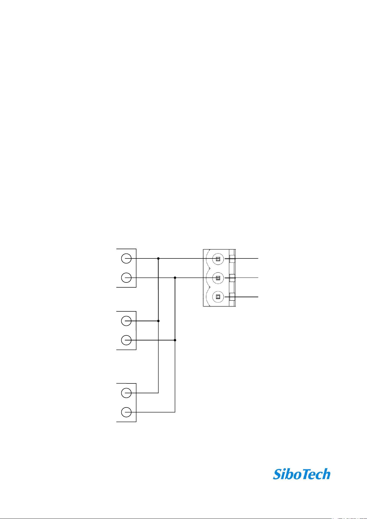
If you are using two power supply, when the way in which the power fails, the other way you can continue to
supply power to ensure normal operation.
Power supply wiring as shown below:
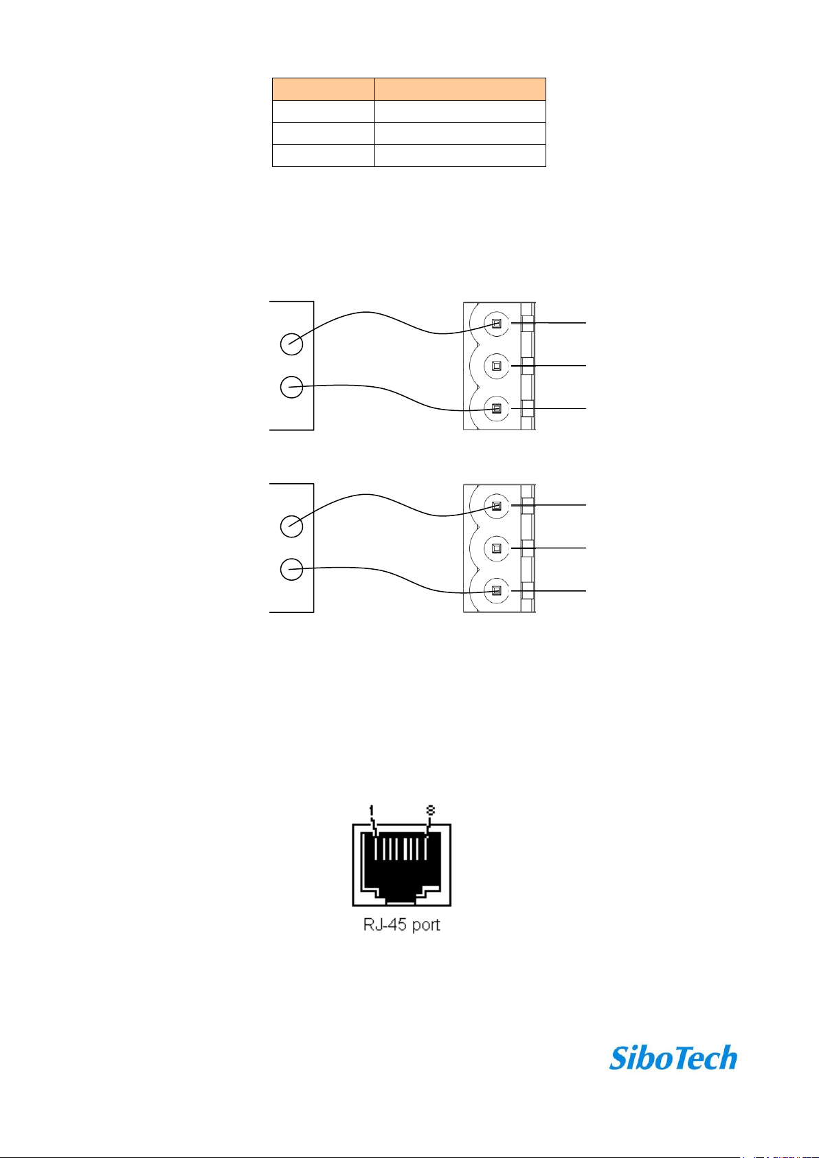
3.4.2 Ethernet interface
Ethernet interface apply RJ-45 connector, 10/100M adaptive.
GND
NC
24V+
1
2
3
GND
24V+
DC power: +24V Ⅰ
Power interface of ENB-302MI
GND
NC
24V+
1
2
3
GND
24V+
Optionally be connected
Must be connected
Power interface of ENB-302MI
(the other)
DC power: +24V Ⅱ

www.sibotech.net
9
Pin
Signal Description
S1
TXD+,Transmit Data+, Output
S2
TXD-,Transmit Data-, Output
S3
RXD+,Receive Data+, Input
S4
Bi-directional Data+
S5
Bi-directional Data-
S6
RXD-,Receive Data-, Input
S7
Bi-directional Data+
S8
Bi-directional Data-
3.4.3 RS-232/RS-485 interface
ENB-302MT support standard RS485 and RS232 interfaces.
RS232 interface:
Pin
Signal Description
1
TX, connect with RX of user device
2
RX, connect with TX of user device
3
GND
RS485 interface:
Pin
Signal Description
1
B+,RS485
2
A-,RS485
3
GND
The RS-485 interface of ENB-302MT is standard, and the RS-485 characteristics of the product are shown
B+
A-
GND
1
2
3
TX
RX
GND
1
2
3
www.sibotech.net
10
as follows:
1. The basic characteristics of RS-485 transmission technology
①Network topology: Linear bus, there are active bus termination resistors at both sides.
②Transfer rate: 300 bps~115.2Kbps.
③Media: Shielded twisted-pair cable and also can cancel the shielding, depending on environmental
conditions (EMC).
④Site number: 32 stations per subsection (without repeater), and can up to 127 stations (with RS485
repeater).
⑤Plug connection: 3-pin pluggable terminal.
2. The main points on RS-485 transmission equipments installation
①All the equipments be connected with RS-485 bus;
②Subsection can be connected up to 32 sites;
③The farthest end of each bus has a termination resistor—120Ω 1/2W to ensure reliable operation of the
network.
B+
A-
GND
1
2
3
485+
485-
RS485 device
RS485 interface of
ENB-302MT
RS485 device
RS485 device
485+
485-
485+
485-
…

www.sibotech.net
11
4 Instructions of Configuration Software
Take the product CD into the computer CD drive, open the CD, and install the configuration software
MT-123. You can easily follow the prompts to complete the installation. Then open the configuration software and
finish the configuration of ENB-302MT!
Note: The factory set of ENB-302MT is DHCP, if the network is no DHCP Server, you can set mode bit (bit
1) to 1(On), and restart ENB-302MT, then the fixed IP address of ENB-302MT is 192.168.0.10, mask is
255.255.255.0, gateway address is 192.168.0.1.
4.1 Note before configuration
MT-123 is a product based on Windows platform, and used to configure parameters of ENB-302MT.
The user to run the software, make sure the user’s computer and the ENB-302MT need to configure in the
same network.
Double-click the icon to access the main interface:
4.2 Search equipment
Before configurating parameters of ENB-302MT, the user need search the gateway using the software.
www.sibotech.net
12
The software provides two ways to search the gateway for the user.
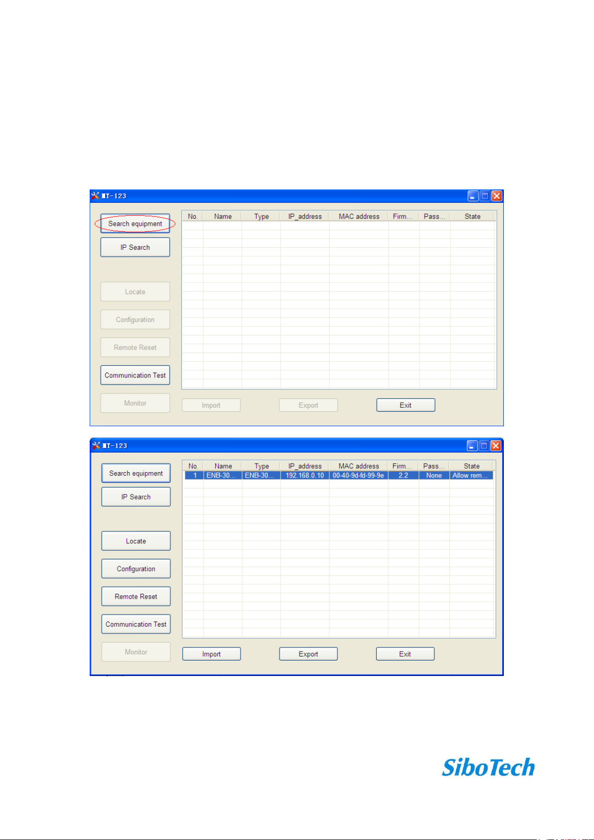
4.2.1 Search all equipments of Ethernet
Click “Search equipment” button of the main interface, the software will search all of the available
ENB-302MT equipments and list them in the main interface.
www.sibotech.net
13
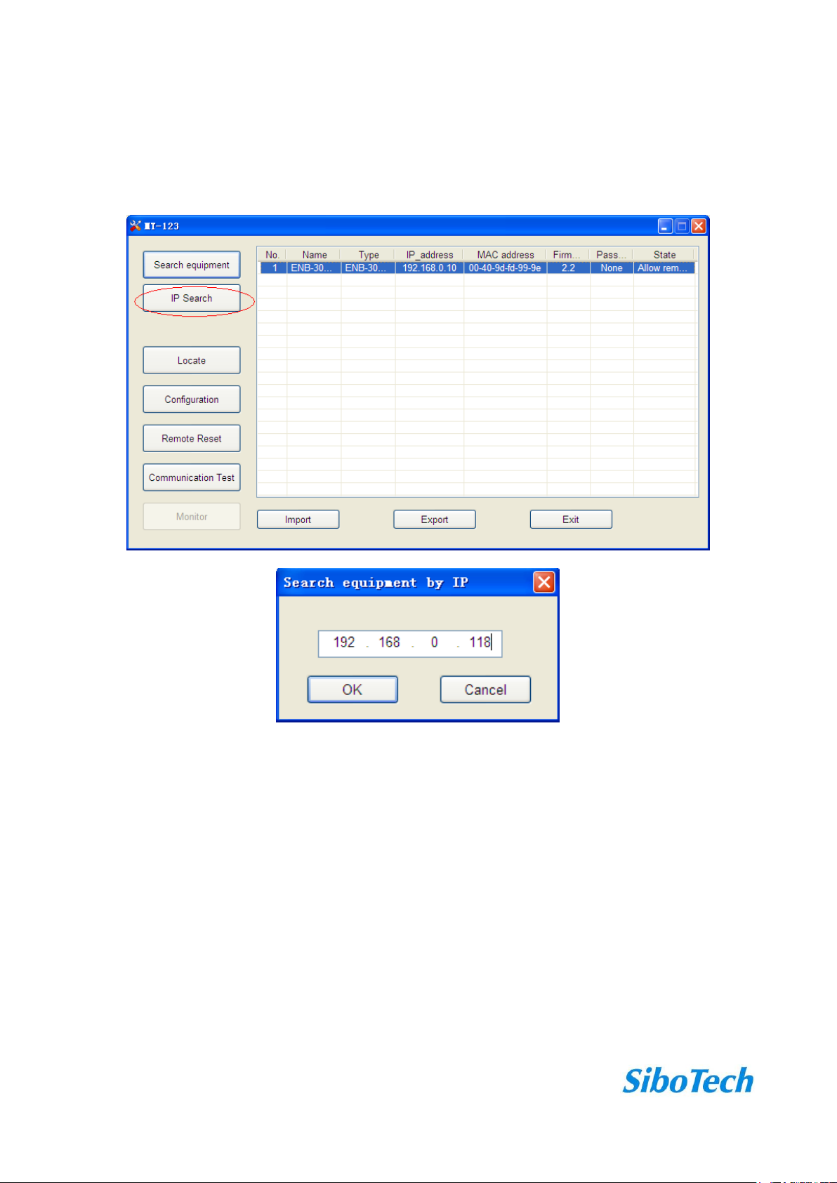
4.2.2 IP search
Click “IP search” button of the main interface will pop up a dialog box, and user need enter the IP address of
ENB-302MT.
After entering the correct IP address, the software will search ENB-302MT with the IP address in the
network, and list the information of the equipment in the main interface.
Note: If the users select the “IP search”, the users need enter correct IP address or it will not search
equipment.
4.3 Configuration
Select the equipment to be configured in the list, and the “Locate”, “Configuration”, “Remote Reset”,
“Import” and “Export” buttons become available:

www.sibotech.net
14
Click “Configuration” button, a password authentication dialog box will pop up if the equipment has been set
with a password:
Pass the password authentication or no password and then enter configuration interface:

www.sibotech.net
15
4.3.1 Operating Modes
ENB-302MT provides two operating modes:
Modbus RTU slave mode----Modbus TCP master communicate with Modbus RTU slave through the
gateway;
Modbus RTU master mode----Modbus TCP salve communicate with Modbus RTU master through the
gateway.
The other two modes: “ASCⅡ salve mode” and “ASCⅡ master mode” will open in a future release.
Operating mode of ENB-302MTis defined by the serial equipment, for example, when want to achieve the
communication between Modbus TCP master device and Modbus RTU slave device,the users need to select
“RTU slave mode” of ENB-302MT.
4.3.2 Ethernet parameters
Ethernet parameters include: “Name”, “IP configuration mode”, “IP address”, “Subnet mask”, “Gateway
address”, “DNS1”, “DNS2”.

www.sibotech.net
16
Name —— Enter a name to identify the device in order to distinguish from other
equipment;
IP_configuration —— Set the device's IP address configuration mode;
IP address —— Set the device's IP address;
Subnet mask —— Set subnet mask of the device;
Gateway_address —— Set gateway address of the device;
DNS1 —— 0.0.0.0 (currently only support 0.0.0.0)
DNS2 —— 0.0.0.0 (currently only support 0.0.0.0)
Note: The name can not have spaces, up to 20 characters, it is best not to use Chinese.
4.3.3 Serial parameters
Serial parameters include: “Baud rate”, “Parity”, “Stop bits”, “Data bits”.

www.sibotech.net
17
Baud rate —— 1200、2400、4800、9600、19200、38400、57600、115200、230400bps;
Parity —— None, Odd, Even, Mark, Space;
Stop bit —— 1, 2;
Data bit —— 8 (currently only support 8 data bits)
4.3.4 ID mapping
Specify request packets send to which serial port or send to which server.
Virtual slave ID range —— Ether an ID range, the left is minimum, the right is maximum (not
more than 247);

www.sibotech.net
18
Offset of slave ID —— D-value of virtual ID with actual ID (can be negative);
Actual salve ID range —— By clicking “Set” button to calculate;
When select “RTU slave mode”, the users need to specify the serial port to be mapped.
When select “RTU master mode”, the users need to set “IP address of target TCP slave”, that is the IP address
of the server to be connected.
After setting “Virtual slave ID range” and “Offset of slave ID”, click “Set” button, “Actual salve ID range”
value is automatically calculated.
When click “Add” button, users can add a message in “Slave ID mapping list”.
When want to modify the added information, users fist select the information you want to modify, and then
set “Virtual slave ID range” and “Offset of slave ID”, click “Modify” button.
When want to delete the added information, users need select the information you want to delete, and click
“Delete” button.
Tip: 1. “Add” and “Modify” button both have “Set” function, users do not need to click “Set” then click
“Add” or “Modify”.
2. Support up to 36 messages.
4.3.5 Modbus parameters
Set “Character time out”, “Response time out” and “Delay between polls” of Modbus RTU in the follow
interface:

www.sibotech.net
19
4.3.6 Priority control
Ethernet speed is faster than serial port, and it will cause the frame line, then you can set priority of frames.
After enabling “Priority control”, user can set, and only “RTU salve mode” supports the function:
Specify the main client —— The requests of specified client priority to send;
Specify the request —— The requests of specified slave ID (virtual ID) or function codes priority
to send.
Priority of requests:
Conditions
Priority
Comply with specified the main master, and comply with specified the request
High
Comply with specified the main master, or comply with specified the request
In
Not comply with priority conditions
Low
Use method of “Add”, “Modify” and “Delete” button in the interface is the same with “ID mapping”
interface.

www.sibotech.net
20
4.3.7 Advanced parameters
Advanced parameters include: “Password”, “Port”, “Startup delay of serial”,“Default value”,“Idle time of
TCP connection and Keep-Alive”, “Limitation of communication IP range”.
Password —— After setting the password, users need to enter the password when configurate
parameters again. If users want to delete the password, just put your password is set to empty.
Default value —— When user click “Default value”, the previous configuration information will
be lost.
Idle time of TCP connection and Keep-Alive —— When a TCP connection idle time reaches the set
Table of contents
Other SiboTech Gateway manuals


