GW-7553-CPM PROFIBUS/CANopen GATEWAY User Manual (Version 1.00, Apr/2016) PAGE: 3
Table of Contents
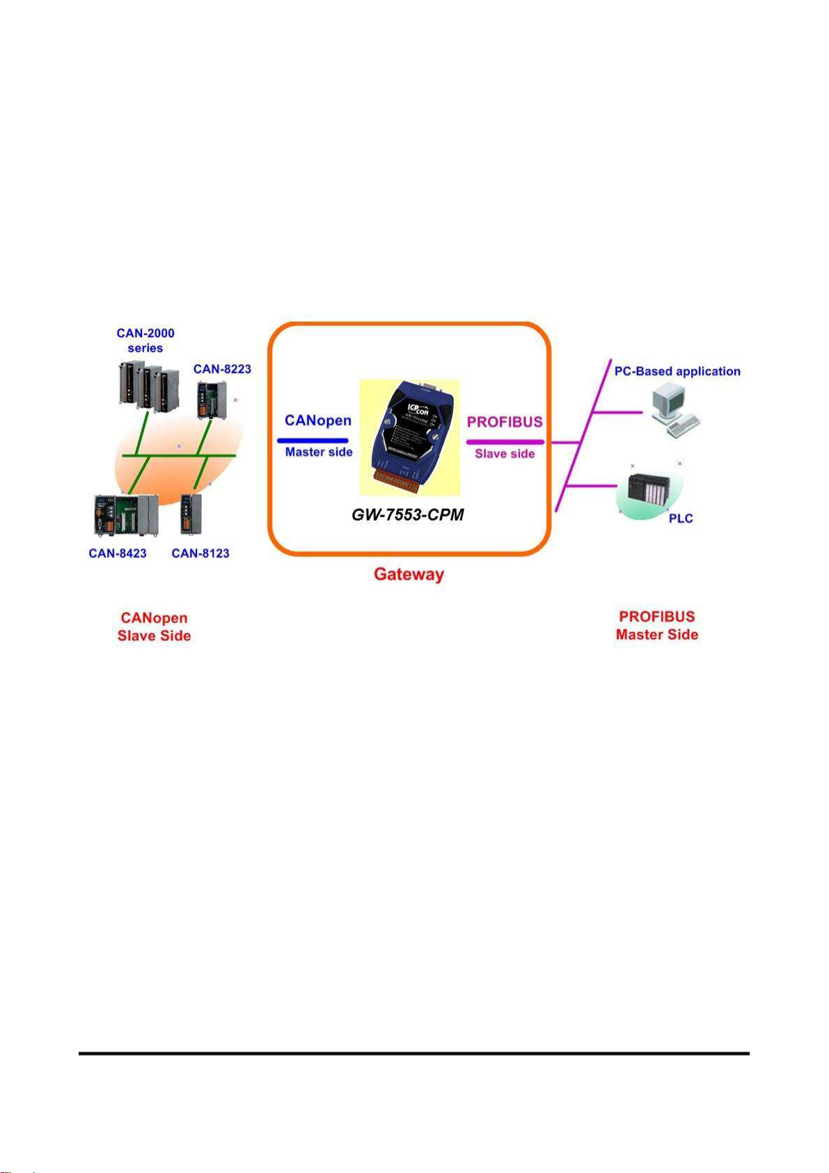
1. Introduction 4
1.1 Features ·······························································································4
1.2 Modules Support····················································································5
1.3 Specification··························································································5
2. Hardware 7
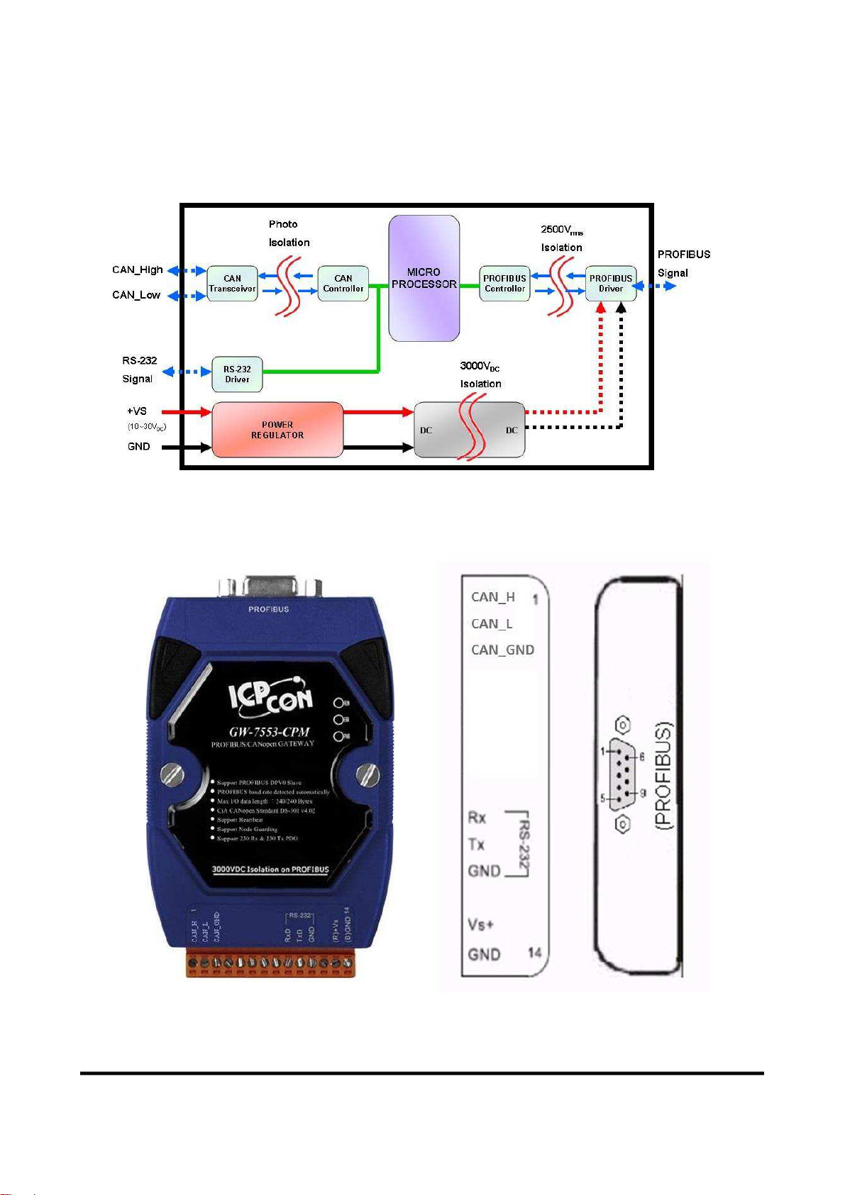
2.1 Block Diagram of GW-7553-CPM ······························································7
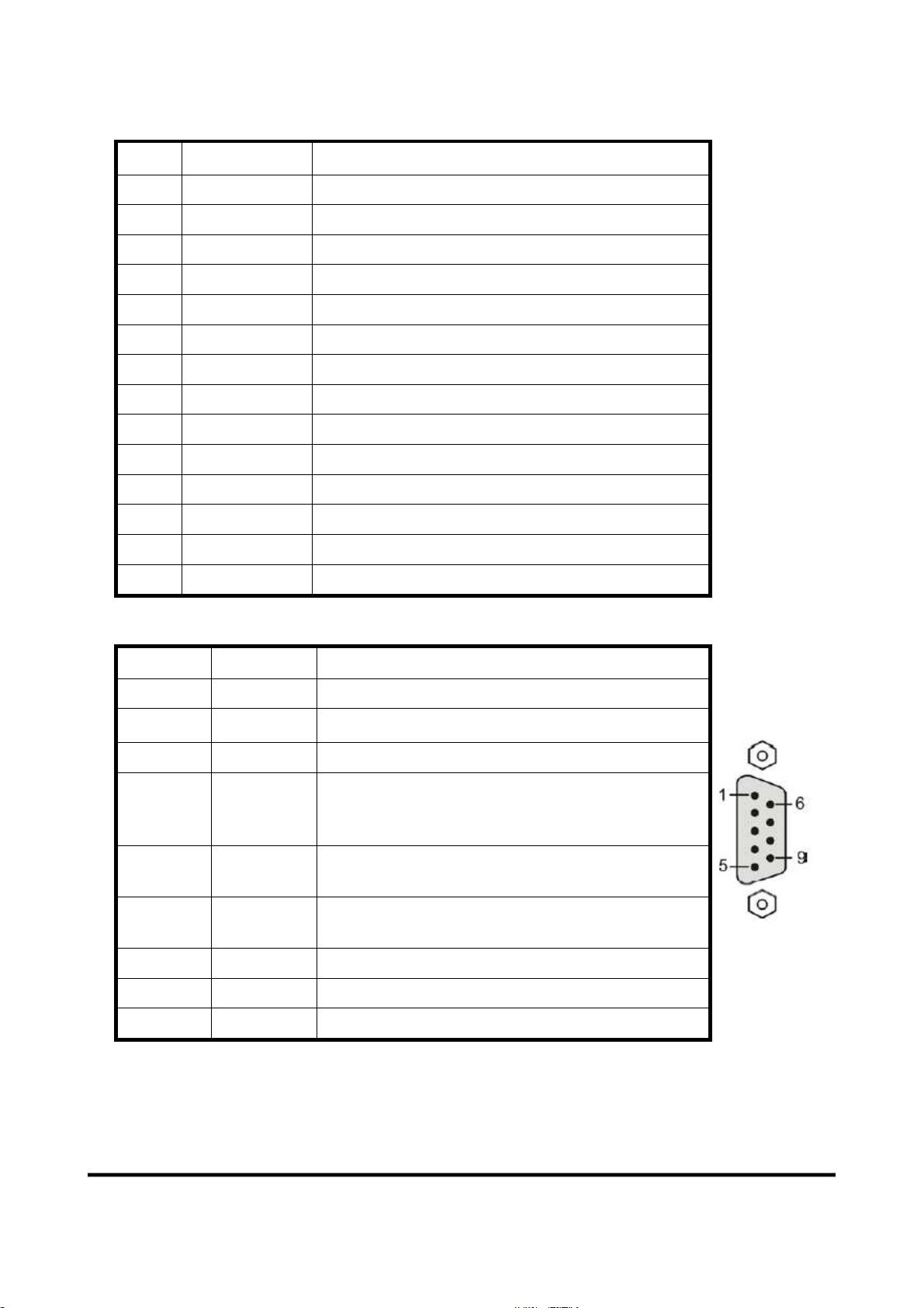
2.2 Pin Assignment······················································································7
2.3 Wiring································································································· 8
2.4 Setting the PROFIBUS Address······························································· 12
2.5 LED status indicator ············································································· 13
2.6 Normal/Setting Dip Switch ····································································· 14
3. Communication protocol transfer theorem 16
3.1 PROFIBUS data exchange······································································ 16
3.2 CANopen data exchange ········································································ 17
3.3 Communication protocol transfer····························································· 18
4. Communication 19
4.1 Field of application ··············································································· 19
4.2 GSD file ····························································································· 21
4.3 The Configuration of the modules····························································· 23
4.4 Diagnostic messages ·············································································· 23
4.5 I/O data exchange················································································· 24
5. Application of Utility 26
5.1 Install Utility······················································································· 26
5.2 Utility introduction ··············································································· 26
6. Troubleshooting 33
7. Dimensions 34
ГК Атлант Инжиниринг – официальный представитель вРФ иСНГ