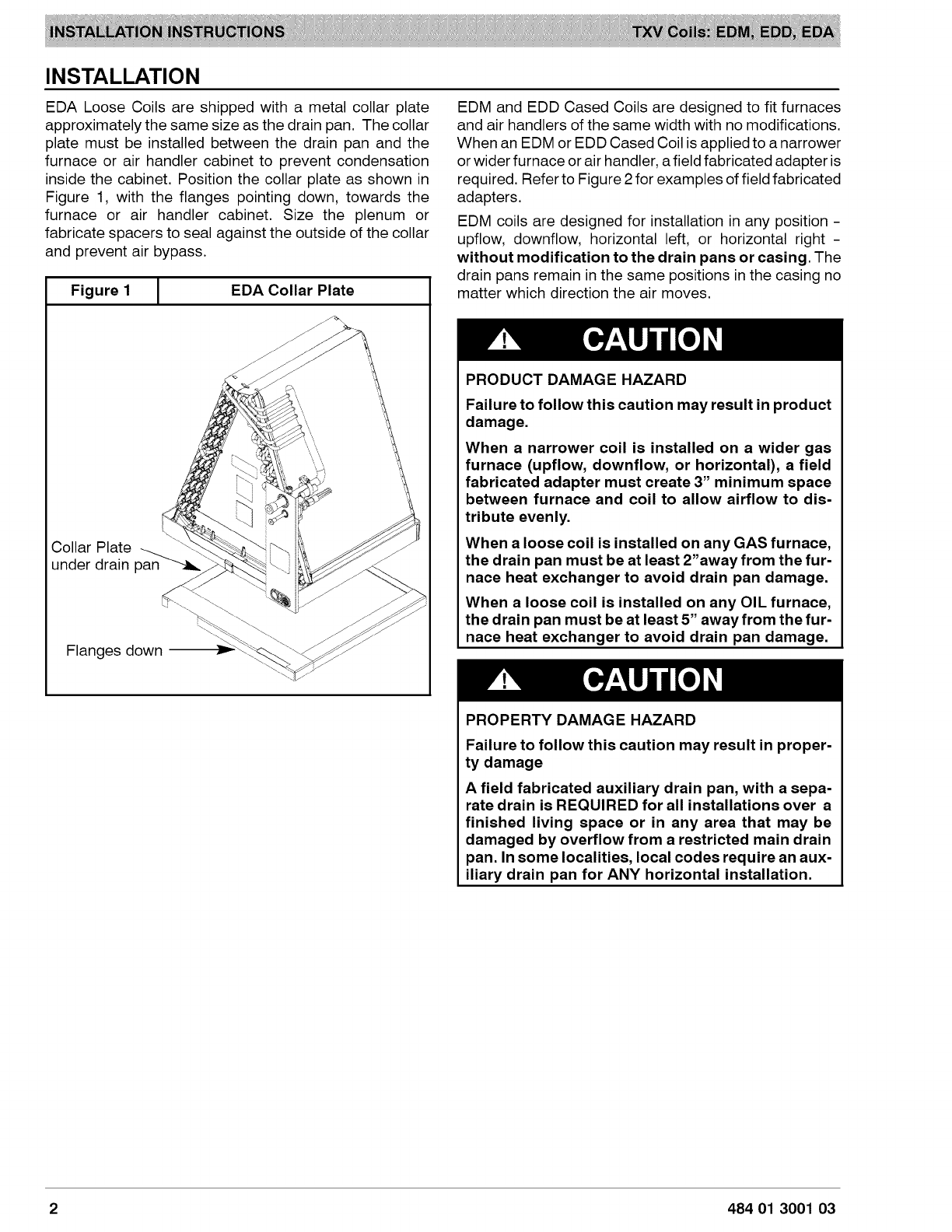
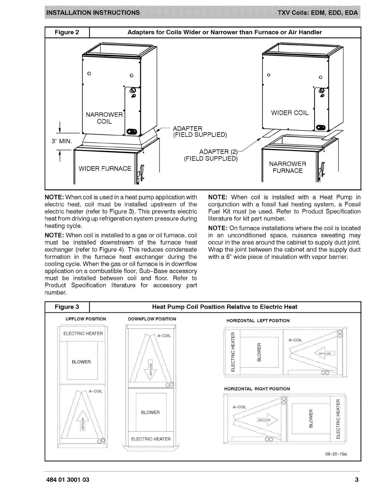
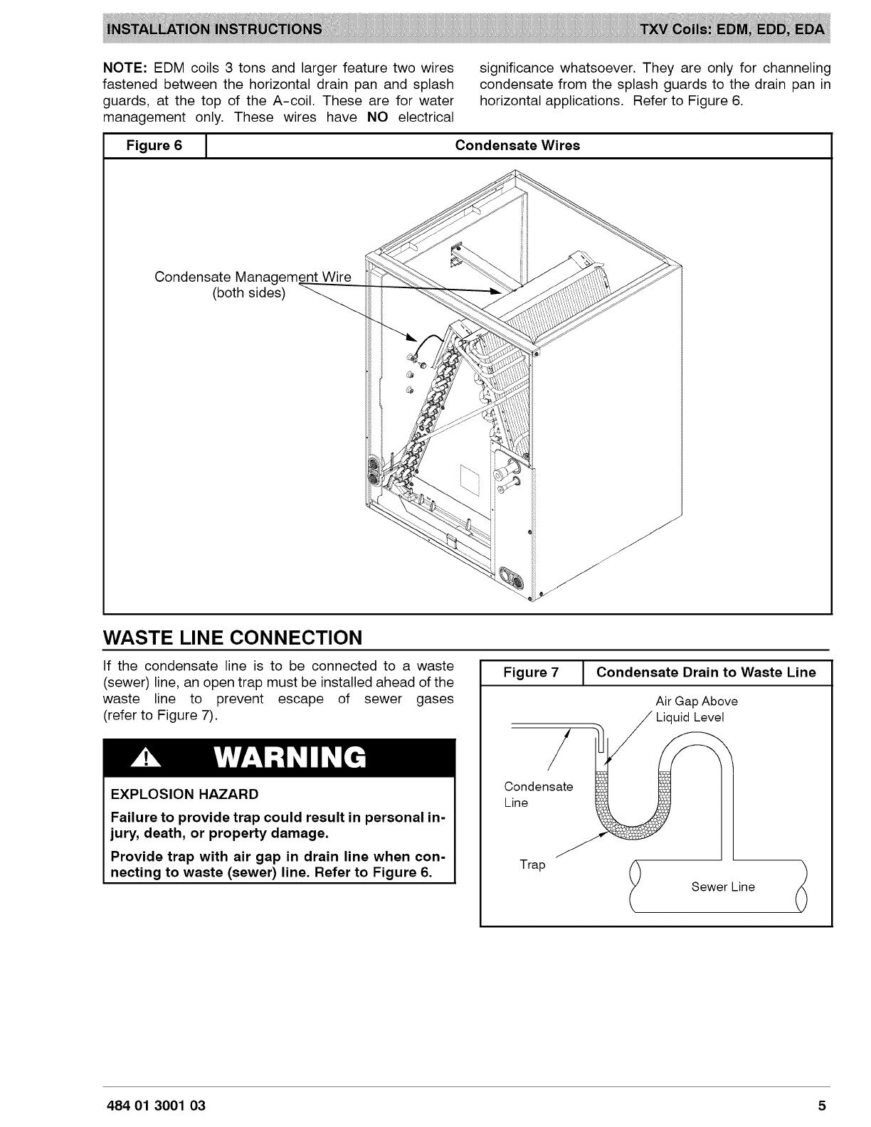
ICP EDM Series User manual
Other ICP Heat Pump manuals

ICP
ICP PDX336080K01A1 User manual

ICP
ICP HMC036KDT1 User manual

ICP
ICP PHX4 User manual

ICP
ICP PYPA Series User manual

ICP
ICP WPH324 User manual

ICP
ICP iMAT 32VBI-ELV User guide

ICP
ICP C4H318GKD200 Installation instructions

ICP
ICP PHD548 User manual

ICP
ICP PHAD60N1K1 User manual

ICP
ICP N4H318AKE100 Installation instructions

ICP
ICP PHF348000K00A1 Quick start guide

ICP
ICP PDX424040K00A1 User manual

ICP
ICP PH55 Series User manual

ICP
ICP RHH120 User manual

ICP
ICP FEM4P Series User manual

ICP
ICP iMAT 14 User guide

ICP
ICP N4H4 User manual

ICP
ICP N4H3 User manual

ICP
ICP HC4H3 User manual

ICP
ICP CHS180 Dimensions and installation guide


Popular Heat Pump manuals by other brands


Mitsubishi Electric
Mitsubishi Electric PUZ-SWM60VAA Service manual

Dimplex
Dimplex LI 16I-TUR Installation and operating instruction

Carrier
Carrier WSHP Open v3 Integration guide

TGM
TGM CTV14CN018A Technical manual

Carrier
Carrier 38MGQ Series installation instructions

Kokido
Kokido K2O K880BX/EU Owner's manual & installation guide

Viessmann
Viessmann VITOCAL 300-G PRO Type BW 2150 Installation and service instructions

Carrier
Carrier 48EZN installation instructions

Viessmann
Viessmann KWT Vitocal 350-G Pro Series Installation and service instructions for contractors

Ariston
Ariston NIMBUS user manual

Weishaupt
Weishaupt WWP L 7 Installation and operating instruction

GE
GE Zoneline AZ85H09EAC datasheet