manuals.online logo
Brands
  1. Home
  2. •
  3. Brands
  4. •
  5. ICP
  6. •
  7. Heat Pump
  8. •
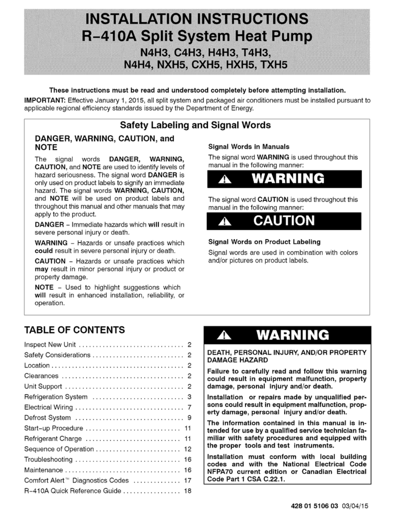
  9. ICP N4H318AKE100 Installation instructions

ICP N4H318AKE100 Installation instructions

This manual suits for next models

13

Other ICP Heat Pump manuals

ICP EDM Series User manual

ICP

ICP EDM Series User manual

ICP HMC036KDT1 User manual

ICP

ICP HMC036KDT1 User manual

ICP WPH324 User manual

ICP

ICP WPH324 User manual

ICP RHH120 User manual

ICP

ICP RHH120 User manual

ICP PDX336080K01A1 User manual

ICP

ICP PDX336080K01A1 User manual

ICP PDX424040K00A1 User manual

ICP

ICP PDX424040K00A1 User manual

ICP HC4H3 User manual

ICP

ICP HC4H3 User manual

ICP PHM324K00A1 User manual

ICP

ICP PHM324K00A1 User manual

ICP PHF Series User manual

ICP

ICP PHF Series User manual

ICP PH55 Series User manual

ICP

ICP PH55 Series User manual

ICP HMC009KD User manual

ICP

ICP HMC009KD User manual

ICP N4H3 User manual

ICP

ICP N4H3 User manual

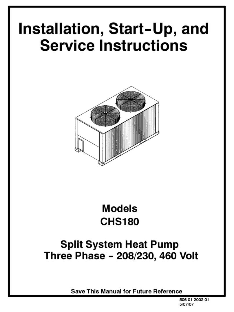
ICP CHS180 Dimensions and installation guide

ICP

ICP CHS180 Dimensions and installation guide

ICP PHF348000K00A1 Quick start guide

ICP

ICP PHF348000K00A1 Quick start guide

ICP FEM4P Series User manual

ICP

ICP FEM4P Series User manual

ICP PYPA Series User manual

ICP

ICP PYPA Series User manual

ICP PHX330000K00A1 User manual

ICP

ICP PHX330000K00A1 User manual

ICP iMAT 14 User guide

ICP

ICP iMAT 14 User guide

ICP C4H418GKD200 Installation instructions

ICP

ICP C4H418GKD200 Installation instructions

ICP PHJ3 Instruction Manual

ICP

ICP PHJ3 Instruction Manual

ICP PHAD60N1K1 User manual

ICP

ICP PHAD60N1K1 User manual

ICP C4H318GKD200 Installation instructions

ICP

ICP C4H318GKD200 Installation instructions

ICP PHX4 User manual

ICP

ICP PHX4 User manual

ICP N4H4 User manual

ICP

ICP N4H4 User manual

Popular Heat Pump manuals by other brands

Daikin RXL12QMVJU Service manual

Daikin

Daikin RXL12QMVJU Service manual

AIREDALE BluCube CUR092V16-1CO-0 Installation and maintenance manual

AIREDALE

AIREDALE BluCube CUR092V16-1CO-0 Installation and maintenance manual

Calyenty RBH 125 Customer's manual

Calyenty

Calyenty RBH 125 Customer's manual

GRE HPGI50 owner's manual

GRE

GRE HPGI50 owner's manual

Carrier 30XW Installation, operation and maintenance instructions

Carrier

Carrier 30XW Installation, operation and maintenance instructions

Hayward SUMHEAT HP5131DT3 Installation instructions manual

Hayward

Hayward SUMHEAT HP5131DT3 Installation instructions manual

REMKO SQW 400 Electrical wiring

REMKO

REMKO SQW 400 Electrical wiring

Sanyo SAP120FCH Service manual

Sanyo

Sanyo SAP120FCH Service manual

Daikin EHYHBH05AA Operation manual

Daikin

Daikin EHYHBH05AA Operation manual

Panasonic WH-SDF03E3E5 Design handbook

Panasonic

Panasonic WH-SDF03E3E5 Design handbook

Airxcel 45000 Series Installation, operation and maintenance instructions

Airxcel

Airxcel 45000 Series Installation, operation and maintenance instructions

Mitsubishi Electric PUZ-SWM60VAA Service manual

Mitsubishi Electric

Mitsubishi Electric PUZ-SWM60VAA Service manual

Dimplex LI 16I-TUR Installation and operating instruction

Dimplex

Dimplex LI 16I-TUR Installation and operating instruction

Carrier WSHP Open v3 Integration guide

Carrier

Carrier WSHP Open v3 Integration guide

Mitsubishi Electric EHSE-YM9EC Service manual

Mitsubishi Electric

Mitsubishi Electric EHSE-YM9EC Service manual

TGM CTV14CN018A Technical manual

TGM

TGM CTV14CN018A Technical manual

Carrier 38MGQ Series installation instructions

Carrier

Carrier 38MGQ Series installation instructions

Kokido K2O K880BX/EU Owner's manual & installation guide

Kokido

Kokido K2O K880BX/EU Owner's manual & installation guide

manuals.online logo
manuals.online logoBrands
  • About & Mission
  • Contact us
  • Privacy Policy
  • Terms and Conditions

Copyright 2025 Manuals.Online. All Rights Reserved.

428 04 5102 01 August 2012
TECHNICAL SUPPORT MANUAL
Split System Heat Pump
N4H3
DANGER, WARNING, CAUTION, and
NOTE
The signal words DANGER, WARNING, CAU-
TION, and NOTE are used to identify levels of haz-
ard seriousness. The signal word DANGER is only
used on product labels to signify an immediate haz-
ard. The signal words WARNING, CAUTION, and
NOTE will be used on product labels and through-
out this manual and other manuals that may apply
to the product.
DANGER -- Immediate hazards which will result in
severe personal injury or death.
WARNING -- Hazards or unsafe practices which
could result in severe personal injury or death.
CAUTION -- Hazards or unsafe practices which
may result in minor personal injury or product or
property damage.
NOTE -- Used to highlight suggestions which will
result in enhanced installation, reliability, or opera-
tion.
Signal Words in Manuals
The signal word WARNING is used throughout this
manual in the following manner:
The signal word CAUTION is used throughout this
manual in the following manner:
Signal Words on Product Labeling
Signal words are used in combination with colors
and/or pictures on product labels.
WARNING
Safety Labeling and Signal Words
!
!CAUTION
WARNING
TABLE OF CONTENTS
Model Number Identification 2.....................
R--410A Quick Reference Guide 3..................
Wiring Diagrams 4--7.............................
Charging Chart 8.................................
Tech Labels (Expanded Data) 9 -- 16................
Parts List 17 -- 22................................
Exploded Views 23 -- 25..........................
Cooling Multiplying Factors 26 -- 52.................
Heating Multiplying Factors 52 -- 78.................
MODELS
N4H318AKE100 N4H318GKE100
N4H324AKE100 N4H324GKE100
N4H330AKE100 N4H330GKE100
N4H336AKE100 N4H336GKE100
N4H342AKE100 N4H342GKE100
N4H348AKE100 N4H348GKE100
N4H360AKB400 N4H360GKB400
!WARNING
DEATH, PERSONAL INJURY, AND/OR PROPERTY
DAMAGE HAZARD
Failure to carefully read and follow this warning
could result in equipment malfunction, property
damage, personal injury and/or death.
Installation or repairs made by unqualified per-
sons could result in equipment malfunction, prop-
erty damage, personal injury and/or death.
The information contained in this manual is in-
tended for use by a qualified service technician fa-
miliar with safety procedures and equipped with
the proper tools and test instruments.
Installation must conform with local building
codes and with the National Electrical Code
NFPA70 current edition or Canadian Electrical
Code Part 1 CSA C.22.1.
TECHNICAL SUPPORT MANUAL Split System Heat Pump: N4H3
2428 04 5102 01
OUTDOOR UNIT MODEL NUMBER IDENTIFICATION GUIDE (single phase)
Digit Position: 1 2 3 4 5, 6 7 8 9 10 11 12
Example Part Number: N 4 H 3 18 G K E 1 0 0
Product Family
4 = R--410A REFRIGERANT
A = Air Conditioner
H = Heat Pump TYPE
3 = 13 SEER
4 = 14 SEER
5 = 15 SEER NOMINAL EFFICIENCY
18 = 18,000 BTUH = 1½tons
24 = 24,000 BTUH = 2 tons
30 = 30,000 BTUH = 2½tons
36 = 36,000 BTUH = 3 tons
42 = 42,000 BTUH = 3½tons
48 = 48,000 BTUH = 4 tons
60 = 60,000 BTUH = 5 tons NOMINAL CAPACITY
A = Standard Grille
G = Coil Guard Grille
C = Coastal FEATURES
K = 208/230--1--60 VOLTAGE
Sales Code
Engineering Revision
Extra Digit
Extra Digit
ACCESSORIES PART NUMBER IDENTIFICATION GUIDE
Digit Position: 123456, 7 8, 9 10, 11
Example Part Number: N A S A 0 01 01 CH
N = Non--Branded BRANDING
A = Accessory PRODUCT GROUP
S = Split System (AC & HP) KIT USAGE
A = Original
B = 2nd Generation MAJOR SERIES
0 = Generic or Not Applicable
2=R--22
4 = R--410A REFRIGERANT
Product Identifier Number
Package Quantity
Type of Kit(Example: CH = Crankcase Heater)
TECHNICAL SUPPORT MANUAL Split System Heat Pump: N4H3
428 04 510201 3
R--410A QUICK REFERENCE GUIDE
•R--410A refrigerant operates at 50% -- 70% higher pressures than R--22. Be sure that servicing equipment and
replacement components are designed to operate with R--410A.
•R--410A refrigerant cylinders are rose colored.
•Recovery cylinder service pressure rating must be 400 psig, DOT 4BA400 or DOT BW400.
•R--410A systems should be charged with liquid refrigerant. Use a commercial type metering device in the
manifold hose when charging into suction line with compressor operating.
•Manifold sets should be 750 psig high--side and 200 psig low--side with 520 psig low--side retard.
•Use hoses with 750 psig service pressure rating.
•Leak detectors should be designed to detect HFC refrigerant.
•R--410A, as with other HFC refrigerants, is only compatible with POE oils.
•Vacuum pumps will not remove moisture from oil.
•Do not use liquid line filter--driers with rated working pressures less than 600 psig.
•Do not install a suction line filter--drier in liquid line.
•POE oils absorb moisture rapidly. Do not expose oil to atmosphere.
•POE oils may cause damage to certain plastics and roofing materials.
•Wrap all filter--driers and service valves with wet cloth when brazing.
•A liquid line filter--drier is required on every unit.
•Do not use with an R--22 TXV.
•If indoor unit is equipped with an R--22 TXV, it must be changed to an R--410A TXV.
•Never open system to atmosphere while it is under a vacuum.
•When system must be opened for service, break vacuum with dry nitrogen and replace all filter--driers. Evacuate
to 500 microns before recharging.
•Do not vent R--410A into the atmosphere.
•Do not use capillary tube indoor coils.
•Observe all WARNINGS,CAUTIONS, NOTES, and bold text.
International Comfort Products, LLC
Lewisburg, TN 37091 USA
TECHNICAL SUPPORT MANUAL Split System Heat Pump: N4H3
442804510201
1. Symbols are electrical representation only.
2. Compressor and fan motor furnished with inherent thermal protection.
3. To be wired in accordance with National Electric N.E.C. and local codes.
4. N.E.C. class 2, 24 V circuit, min. 40 VA required, 60 VA on units installed with LLS.
5. Connection for typical heat pump thermostat. For other arrangements see installation instructions.
6. Use copper conductors only. Use conductors suitable for at least 75° C (167° F).
7. If indoor section has a transformer with a grounded secondary, connect the grounded side to “C” on the circuit board.
8. When start capacitor and relay are installed, start thermistor (PTC) is not used.
9. CH not used on all units.
10. If any of the original wire, as supplied, must be replaced, use the same or equivalent wire.
11. Check all electrical connections inside control box for tightness.
12. Do not attempt to operate unit until service valves have been opened.
13. Do not rapid cycle compressor. Compressor must be off 3 minutes to allow pressures to equalize between high and low
side before starting.
Model Sizes: 18, 24, 30, 36, 42, 48
Notes:
336749--101 REV.A
TECHNICAL SUPPORT MANUAL Split System Heat Pump: N4H3
428 04 510201 5
Model Sizes: 18, 24, 30, 36, 42, 48
336749--101 REV.A
TECHNICAL SUPPORT MANUAL Split System Heat Pump: N4H3
642804510201
1. Symbols are electrical representation only.
2. Compressor and fan motor furnished with inherent thermal protection.
3. To be wired in accordance with National Electric N.E.C. and local codes.
4. N.E.C. class 2, 24 V circuit, min. 40 VA required, 60 VA on units installed with LLS.
5. Connection for typical heat pump thermostat. For other arrangements see installation instructions.
6. Use copper conductors only. Use conductors suitable for at least 75° C (167° F).
7. If indoor section has a transformer with a grounded secondary, connect the grounded side to “C” on the circuit board.
8. When start capacitor and relay are installed, start thermistor (PTC) is not used.
9. CH not used on all units.
10. If any of the original wire, as supplied, must be replaced, use the same or equivalent wire.
11. Check all electrical connections inside control box for tightness.
12. Do not attempt to operate unit until service valves have been opened.
13. Do not rapid cycle compressor. Compressor must be off 3 minutes to allow pressures to equalize between high and low
side before starting.
Notes:
Model Size: 60
TECHNICAL SUPPORT MANUAL Split System Heat Pump: N4H3
428 04 510201 7
Model Size: 60
TECHNICAL SUPPORT MANUAL Split System Heat Pump: N4H3
8428 04 5102 01
R--410A CHARGING CHART
Measured Liquid
Pressure (psig)
Rating Plate (required) Subcooling Temperature °F(°C)
°F (°C) °F (°C) °F (°C) °F(° C) F(° C) F (°C)
6 3 8 4 10 612 714 816 9
R--410A Required Liquid Line Temperature °F(°C)
251 78 26 76 24 74 23 72 22 70 21 68 20
259 80 27 78 26 76 24 74 23 72 22 70 21
266 82 28 80 27 78 26 76 24 74 23 72 22
274 84 29 82 28 80 27 78 26 76 24 74 23
283 86 30 84 29 82 28 80 27 78 26 76 24
291 88 31 86 30 84 29 82 28 80 27 78 26
299 90 32 88 31 86 30 84 29 82 28 80 27
308 92 33 90 32 88 31 86 30 84 29 82 28
317 94 34 92 33 90 32 88 31 86 30 84 29
326 96 36 94 34 92 33 90 32 88 31 86 30
335 98 37 96 36 94 34 92 33 90 32 88 31
345 100 38 98 37 96 36 94 34 92 33 90 32
364 104 40 102 39 100 38 98 37 96 36 94 34
374 106 41 104 40 102 39 100 38 98 37 96 36
384 108 42 106 41 104 40 102 39 100 38 98 37
395 110 43 108 42 106 41 104 40 102 39 100 38
406 112 44 110 43 108 42 106 41 104 40 102 39
416 114 46 112 44 110 43 108 42 106 41 104 40
427 116 47 114 46 112 44 110 43 108 42 106 41
439 118 48 116 47 114 46 112 44 110 43 108 42
450 120 49 118 48 116 47 114 46 112 44 110 43
462 122 50 120 49 118 48 116 47 114 46 112 44
474 124 51 122 50 120 49 118 48 116 47 114 46
TECHNICAL SUPPORT MANUAL Split System Heat Pump: N4H3
428 04 510201 9
MULTIPLYING FACTORS
(Refer to pages 7--13)
† Total capacities are net (I.D. blower heat subtracted) system capacities based on 25’ line set.
If additional tubing length and/or indoor unit is located above outdoor unit, a slight variation in capacity may occur.
†† At TVA rating indoor condition (75 °Fdb, 63 °Fwb), all other indoor air temperatures are at 80 °Fdb
If additional tubing length and/or indoor unit is located above outdoor unit, a slight variation in capacity may occur.
* System amps are total of indoor and outdoor amps.
‡ Chart data is for 80°F indoor dry bulb. For indoor db temperatures other than 80°F, measure Indoor db and Indoor CFM, and plug these into the
formula below. Measure outdoor db and indoor wet bulb, apply these to the chart above, find MBh and S/T, and plug these into the formula below.
(Note: if indoor db is the only thing changing, total capacity, MBh, stays the same.)
Sensible Capacity at Indoor db LOWER than 80 °F=(MBhxS/T) -- ( 80 -- Indoor db ) x 835 x Indoor CFM
1000
()
Sensible Capacity at Indoor db HIGHER than 80 °F=(MBhxS/T)+
( Indoor db -- 80 ) x 835 x Indoor CFM
1000
()
TECHNICAL SUPPORT MANUAL Split System Heat Pump: N4H3
10 428 04 5102 01
2776††3626752776††3626752776††3626752776††3626752776††362675MFC
MBh† 16.57 17.25 17.63 19.20 21.1 8 15.8 6 16.3 4 16.6 9 18.1 7 20.2 1 14.8 6 15.1 6 15.6 2 17.06 19.0 7 13.70 13.73 13.86 15.82 17.7 4 12.5 3 12.5 6 12.2 7 13.8 5 16.30
S/T‡ 1.00 0.91 0.72 0.69 0.51 1.00 0.93 0.74 0.71 0.52 1.00 0.97 0.76 0.73 0.53 1.00 1.00 0.80 0.75 0.54 1.00 1.00 0.85 0.80 0.55
AMPS* 5.36 5.37 5.38 5.41 5.45 5.98 6.00 6.01 6.06 6.12 6.59 6.62 6.67 6.76 6.85 7.32 7.32 7.32 7.50 7.66 8.14 8.14 8.13 8.22 8.51
HI PR 269 272 273 276 282 311 313 314 31 9 325 352 354 358 365 372 400 400 400 41 3 424 453 453 452 458 477
LO PR 125 129 13 1 140 152 128 132 134 143 155 134 135 136 146 159 14 0 140 141 149 163 146 147 145 154 166
MBh† 17.35 17.73 18.07 19.62 21.5 8 16.5 9 16.7 7 17.0 5 18.5 8 20.5 9 15.7 4 15.7 7 15.9 6 17.40 19.4 4 14.46 14.49 14.24 16.13 18.0 8 13.1 8 13.2 0 12.5 6 14.2 1 16.60
S/T‡ 1.00 0.95 0.75 0.72 0.52 1.00 0.98 0.77 0.74 0.53 1.00 1.00 0.79 0.76 0.54 1.00 1.00 0.84 0.79 0.56 1.00 1.00 0.89 0.85 0.58
AMPS* 5.48 5.49 5.48 5.51 5.56 6.10 6.11 6.12 6.17 6.23 6.78 6.79 6.79 6.88 6.96 7.46 7.46 7.44 7.63 7.77 8.28 8.28 8.24 8.35 8.65
HI PR 272 273 274 278 283 314 314 315 32 0 326 359 359 360 366 373 403 403 402 41 5 425 456 456 453 461 480
LO PR 130 133 13 4 143 155 134 135 137 146 158 138 138 139 149 162 14 4 144 143 152 166 151 151 147 156 169
MBh† 18.03 18.14 18.39 19.94 21.8 6 17.2 0 17.2 2 17.3 4 18.8 8 20.8 8 16.3 2 16.3 4 16.2 2 17.66 19.7 1 15.13 15.16 14.5 5 16.3 7 18.3 6 13.7 3 13.7 6 12.8 1 14.4 9 16.80
S/T‡ 1.00 0.99 0.78 0.75 0.54 1.00 1.00 0.80 0.77 0.55 1.00 1.00 0.83 0.80 0.56 1.00 1.00 0.87 0.83 0.58 1.00 1.00 0.93 0.89 0.60
AMPS* 5.58 5.58 5.58 5.61 5.67 6.22 6.22 6.23 6.27 6.35 6.92 6.92 6.91 6.99 7.08 7.61 7.62 7.56 7.75 7.89 8.41 8.41 8.36 8.48 8.78
HI PR 274 274 275 279 285 316 316 317 321 328 362 362 361 36 8 375 408 408 404 417 427 459 459 455 463 482
LO PR 135 136 13 7 146 157 139 139 139 149 161 142 143 141 152 164 14 8 148 145 154 168 154 154 149 158 171
570756570756570756570756570756570756570756570756MFC
MBh† 5.41 5.1 5 4.8 7 7.5 4 7.2 7 6.9 9 10.0 8 9.5 8 9.2 7 12.3 8 12.1 5 11.9 2 14.9 0 14.6 3 14.3 5 17.6 9 17.39 17.0 7 19.9 8 19.8 0 19.5 9 22.1 5 22.0 3 21.88
T/R 10.30 9.80 9.20 14.40 13.8 0 13.3 0 19.2 0 18.2 0 17.6 0 23.6 0 23.1 0 22.6 0 28.40 27.80 27.20 33.70 33.00 32.4 0 38.0 0 37.6 0 37.1 0 42.2 0 41.9 0 41.50
AMPS* 4.78 4.98 5.19 5.01 5.22 5.45 5.26 5.46 5.70 5.48 5.73 5.99 5.74 6.00 6.28 6.06 6.36 6.65 6.32 6.62 6.94 6.61 6.94 7.28
HI PR 216 231 247 231 247 264 251 266 283 269 287 306 293 31 1 329 319 339 358 340 360 381 362 384 406
LO PR 39 39 40 50 50 50 62 62 63 76 76 77 92 92 93 11 0 11 0 11 1 124 126 127 138 140 142
MBh† 5.52 5.2 7 4.9 8 7.6 7 7.4 1 7.1 3 10.2 3 9.7 5 9.4 4 12.5 5 12.3 3 12.0 9 15.1 3 14.8 5 14.5 7 17.81 17.6 0 17.3 3 19.8 1 19.7 2 19.5 7 21.6 2 21.6 5 21.60
T/R 9.20 8.80 8.30 12.80 12.3 0 11.8 0 17.0 0 16.2 0 15.7 0 20.9 0 20.5 0 20.1 0 25.20 24.70 24.20 29.70 29.30 28.70 33.0 0 32.8 0 32.5 0 36.0 0 36.0 0 35.80
AMPS* 4.84 5.04 5.25 5.04 5.26 5.48 5.27 5.47 5.71 5.45 5.70 5.96 5.69 5.95 6.22 5.94 6.23 6.53 6.15 6.46 6.77 6.36 6.70 7.04
HI PR 213 229 245 227 243 260 244 259 277 261 279 297 282 30 0 319 304 324 344 321 342 364 338 361 384
LO PR 39 39 40 50 50 50 62 62 63 76 76 76 92 92 93 108 11 0 11 1 120 123 125 131 135 137
MBh† 5.62 5.3 7 5.0 9 7.7 9 7.5 4 7.2 6 10.3 6 9.9 3 9.5 9 12.7 1 12.4 8 12.2 4 15.3 2 15.0 4 14.7 6 17.79 17.6 6 17.4 7 19.6 1 19.5 4 19.4 7 20.9 9 21.1 1 21.18
T/R 8.30 7.90 7.50 11.5 0 11.1 0 10.7 0 15.3 0 14.7 0 14.1 0 18.8 0 18.5 0 18.1 0 22.70 22.2 0 21.80 26.3 0 26.10 25.8 0 29.1 0 28.9 0 28.7 0 31.1 0 31.20 31.20
AMPS* 4.90 5.10 5.32 5.09 5.31 5.53 5.29 5.50 5.74 5.45 5.70 5.96 5.67 5.93 6.19 5.87 6.15 6.45 6.05 6.35 6.66 6.19 6.52 6.87
HI PR 211 226 243 223 240 256 239 255 272 254 272 290 274 29 2 311 292 312 333 307 328 350 319 342 365
LO PR 39 39 39 50 50 50 62 62 63 76 76 76 91 92 92 106 108 11 0 11 7 120 122 125 129 132
Entering Indoor Temperature -- Degrees F, Dry Bulb
525
600
675
018 Size Outdoor With FS(M,U)4P18**A* Indoor Heating
Outdoor Ambient Temperature -- Degrees F, Dry Bulb
76757473727173--
HEATING
Entering Indoor Temperature --DegreesF,WetBulb
525
600
675
018 Size Outdoor With FS(M,U)4P18**A* Indoor Cooling
Outdoor Ambient Temperature -- Degrees F, Dry Bulb
511501595857
COOLING