manuals.online logo
Brands
  1. Home
  2. •
  3. Brands
  4. •
  5. ICP
  6. •
  7. Heat Pump
  8. •
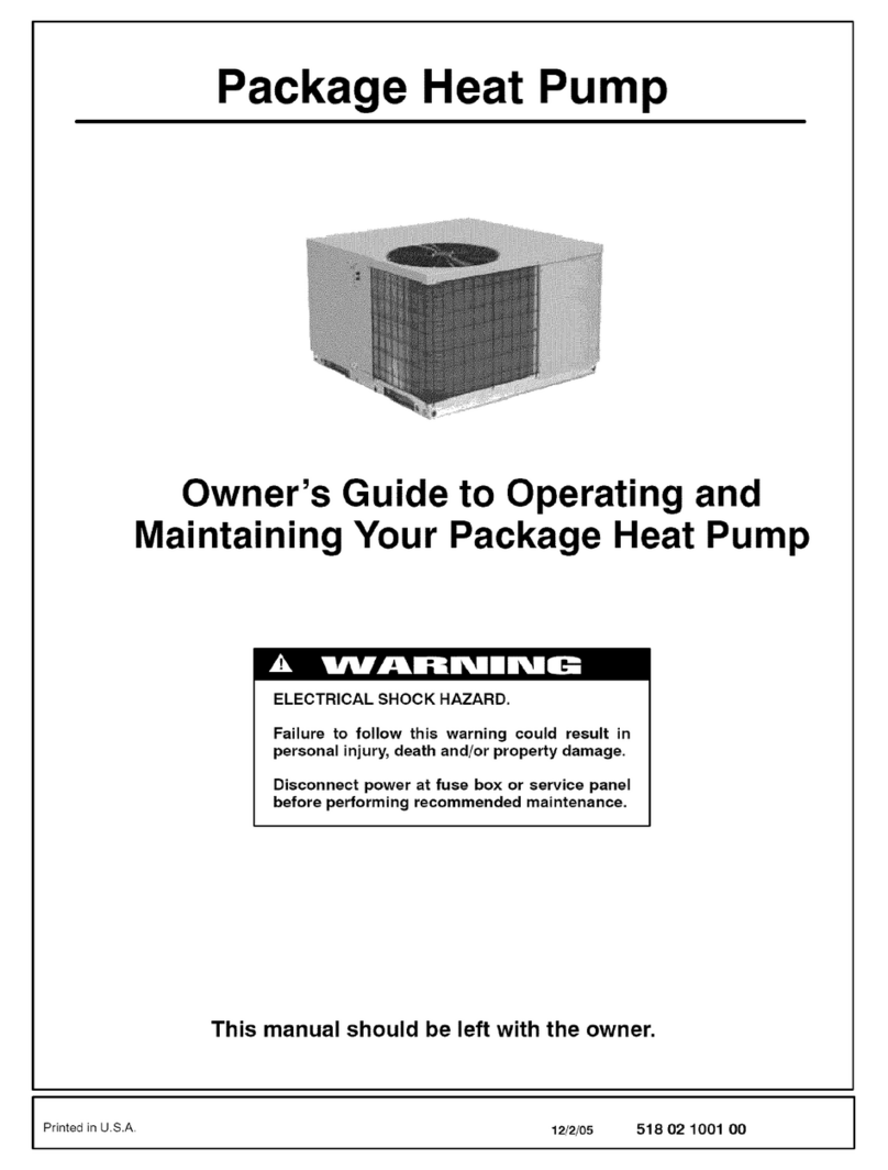
  9. ICP PYPA Series User manual

ICP PYPA Series User manual

This manual suits for next models

1

Other ICP Heat Pump manuals

ICP N4H4 User manual

ICP

ICP N4H4 User manual

ICP HMC009KD User manual

ICP

ICP HMC009KD User manual

ICP PH55 Series User manual

ICP

ICP PH55 Series User manual

ICP PHF Series User manual

ICP

ICP PHF Series User manual

ICP C4H418GKD200 Installation instructions

ICP

ICP C4H418GKD200 Installation instructions

ICP RHH120 User manual

ICP

ICP RHH120 User manual

ICP PHX4 User manual

ICP

ICP PHX4 User manual

ICP PDX424040K00A1 User manual

ICP

ICP PDX424040K00A1 User manual

ICP iMAT 14 User guide

ICP

ICP iMAT 14 User guide

ICP HC4H3 User manual

ICP

ICP HC4H3 User manual

ICP EDM Series User manual

ICP

ICP EDM Series User manual

ICP C4H318GKD200 Installation instructions

ICP

ICP C4H318GKD200 Installation instructions

ICP N4H3 User manual

ICP

ICP N4H3 User manual

ICP PHM324K00A1 User manual

ICP

ICP PHM324K00A1 User manual

ICP PDX336080K01A1 User manual

ICP

ICP PDX336080K01A1 User manual

ICP CHS180 Dimensions and installation guide

ICP

ICP CHS180 Dimensions and installation guide

ICP PHD548 User manual

ICP

ICP PHD548 User manual

ICP PHAD60N1K1 User manual

ICP

ICP PHAD60N1K1 User manual

ICP iMAT 32VBI-ELV User guide

ICP

ICP iMAT 32VBI-ELV User guide

ICP PHJ3 Instruction Manual

ICP

ICP PHJ3 Instruction Manual

ICP HMC036KDT1 User manual

ICP

ICP HMC036KDT1 User manual

ICP PHF3 User manual

ICP

ICP PHF3 User manual

ICP N4H318AKE100 Installation instructions

ICP

ICP N4H318AKE100 Installation instructions

ICP WPH324 User manual

ICP

ICP WPH324 User manual

Popular Heat Pump manuals by other brands

Daikin RXL12QMVJU Service manual

Daikin

Daikin RXL12QMVJU Service manual

AIREDALE BluCube CUR092V16-1CO-0 Installation and maintenance manual

AIREDALE

AIREDALE BluCube CUR092V16-1CO-0 Installation and maintenance manual

Calyenty RBH 125 Customer's manual

Calyenty

Calyenty RBH 125 Customer's manual

GRE HPGI50 owner's manual

GRE

GRE HPGI50 owner's manual

Carrier 30XW Installation, operation and maintenance instructions

Carrier

Carrier 30XW Installation, operation and maintenance instructions

Hayward SUMHEAT HP5131DT3 Installation instructions manual

Hayward

Hayward SUMHEAT HP5131DT3 Installation instructions manual

REMKO SQW 400 Electrical wiring

REMKO

REMKO SQW 400 Electrical wiring

Sanyo SAP120FCH Service manual

Sanyo

Sanyo SAP120FCH Service manual

Daikin EHYHBH05AA Operation manual

Daikin

Daikin EHYHBH05AA Operation manual

Panasonic WH-SDF03E3E5 Design handbook

Panasonic

Panasonic WH-SDF03E3E5 Design handbook

Airxcel 45000 Series Installation, operation and maintenance instructions

Airxcel

Airxcel 45000 Series Installation, operation and maintenance instructions

Mitsubishi Electric PUZ-SWM60VAA Service manual

Mitsubishi Electric

Mitsubishi Electric PUZ-SWM60VAA Service manual

Dimplex LI 16I-TUR Installation and operating instruction

Dimplex

Dimplex LI 16I-TUR Installation and operating instruction

Carrier WSHP Open v3 Integration guide

Carrier

Carrier WSHP Open v3 Integration guide

Mitsubishi Electric EHSE-YM9EC Service manual

Mitsubishi Electric

Mitsubishi Electric EHSE-YM9EC Service manual

TGM CTV14CN018A Technical manual

TGM

TGM CTV14CN018A Technical manual

Carrier 38MGQ Series installation instructions

Carrier

Carrier 38MGQ Series installation instructions

Kokido K2O K880BX/EU Owner's manual & installation guide

Kokido

Kokido K2O K880BX/EU Owner's manual & installation guide

manuals.online logo
manuals.online logoBrands
  • About & Mission
  • Contact us
  • Privacy Policy
  • Terms and Conditions

Copyright 2025 Manuals.Online. All Rights Reserved.

Installation Instructions
I DIRECT DRIVE BLOWER
PH55/PYPA SERIES
THREE PHASE
SINGLE PACKAGE HEAT
_) PUMPS
ELECTRIC HEAT c
(OPTIONAL)
TABLEOFCONTENTS
1, SAFETYLABELINGANDSIGNALWORDS .................... 2
2. UNITDIMENSIONS ...................................... 2
3, SAFEINSTALLATIONREQUIREMENTS....................... 2
4. LOCATINGTHE UNIT .................................... 2
5, UNITELECTRICALWIRING................................ 4
6. ELECTRICHEATINSTALLATIONGENERALINFORMATION....... 6
7.AIR DISTRIBUTIONSYSTEM .............................. 8
8. START-UPPROCEDURES................................ 8
9. SEQUENCEOFOPERATION ............................. 10
Printed in U.S.A. LP-1 10/15/01 427 01 1005 00
1. Safety Labeling and Signal Words
Danger, Warning and Caution
The signal words DANGER, WARNING and CAUTION are used to identify levels of hazard seriousness. The signal word DANGER is
only used on product labels to signify an immediate hazard. The signal words WARNING and CAUTION wil! be used on product labels
and throughout this manual and other manuals that may apply to the product.
2. Dimensions
NOTE: DUCTCOLLARSATTACHEDTOSUPPLYANDRETURNMUSTBEREVERSEDATINSTALLATION.SEEINSTRUCTIONSONPAGE3.
ALL DIMENSIONS IN INCHES
261/2
PRESSURE
PORTS
COIL
ACCESS
PANEL
26 s/4
51 \
CONDENSATE DRAIN
CONNECTION
ROUND FLANGE
WILL 3/8 DIA HOLE**
ACCOMMODATE
14" DIA.
RETURN DUCT
m___ 10
3 11/2
41
* ELECTRICAL ACCESS FOR LINE VOLTAGE POWER SUPPLY-ONE FOR UNIT, ONE FOR HEATER
** FOR LOW VOLTAGE WIRING
1/4 DIA.*
1/4 DIA.*
9
_1 1/2
ROUND SHAPED FLANGE WILL
ACCOMMODATE 12" DiA
SUPPLY DUCT
3. Safe Installation Requirements 4. Locating The Unit
Installation or repairs made by unqualified persons can
result in hazards to you and others. Installation MUST
conform with local building codes or, in the absence of
local codes, with the National Electrical Code
NFPA70-1990 or current edition.
The information contained in this manual is intended
for use by a qualified service technician familiar with
safety procedures and equipped with the proper tools
and test instruments.
Failure to carefully read and follow all instructions in
this manual can result in unit malfunction, property
damage, personal injury and/or death.
The unit is designed for outdoor installation only. Place the unit on
a platform at ground level. The unit may be installed on a concrete
slab of 48" (1219mm) x 48" (1219mm) dimensions. Cement
blocks on a 3" sand footing will also work. The slab or blocks
SHOULD NOT be in contact with any part of the structure. Check
local codes covering zoning, noise, platforms, etc..
If practical avoid locating next to fresh air intakes, vent or bed-
room windows. Noise may carry into the openings and disturb
people inside.
Avoid installations under roof overhangs without guttering. Water
draining from the roof onto the unit could produce excessive
noise, and may cause ice to build up on coil or fan.
Placement of the unit should be in a well drained area or the unit
MUST be supported high enough so runoff will not enter the unit.
Do not locate unit where heat, lint or exhaust fumes wil! be dis-
charged on unit (as from dryer vents.)
• Seal supply and return air ducts.
• Check to see that filters are installed correctly and are the
proper type and size.
NOTE: It is the personal responsibility and obligation of the cus-
tomer to contact aqualified installer to ensure that the installation
is adequate and conforms to governing codes and ordinances.
CAUTION
Do NOT operate unit in a corrosive atmosphere containing
chlorine, fluorine, or any other corrosive chemicals.
Clearances
Minimum clearances, as specified in FIGURE 1, MUST be main-
tained from adjacent structures to provide adequate air circula-
tion and room for service personnel.
While minimum clearances are acceptable for safety reasons,
they may not allow adequate air circulation around the unit for
proper operation. Whenever possible, it is desirable to allow addi-
tional clearance, especially around the condenser inlet and dis-
charge openings.
Do NOT install the unit in a recessed or confined area that will per-
mit discharged air from the condenser to recirculate to the con-
denser inlet. 427 01 1005 00
2
Minimum Clearances to Combustible Construction
SERVICE ACCESS CLEARANCES
Blower Access Panel Side ................... 30" (762mm)
Electrical Access Panel Side ................. 30" (762mm)
OPERATIONAL CLEARANCES
Combustible Base
(Wood or Class A, B or C
roof covering material) .................... 0"
Supply and Return Air Ducts ........................... 0"
Duct Connection Side
....................................... 0 _
Clearance between Overhang
and Top of Unit ............... 48" (1219mm)
Clearance around Condenser Coil area to wall or shrubs .10"
FIGURE Minimum Clearances and Access Panels
Overhang
Evaporator 48" Minimum Overhang Clearance
Access Panel
10"around
b( condenser
coil area
Blower/Electrical
Access Panel
Cover Plate
Installation
CAUTION
The unit must be installed with a slope no greater than 1/8"
per foot (lOmm per meter). For side to side leveling, the con-
densate drain side side MUST always be lower.
The unit MUST be situated in such a way as to provide safe
access for servicing.
The platform may be made of either concrete or pressure
treated wood and MUST be level and strong enough to
support the unit's weight.
Position platform separate from the building's foundation.
Install in a well-drained area, with the top surface of the
platform above grade level and above the average winter
snow levels to prevent coi! blockage.
Platform MUST be high enough to allow for proper conden-
sate drainage.
Installing Duct Collars
Duct collars are supplied with the unit and are attached to the sup-
ply and return openings with the flanges to the inside and must be
reversed before unit's installation.
1. Remove the screws from the collars and reverse them so
the flange is to the outside.
2. Make sure when pushing the collars into place that the "V"
flange of the collars seats into the supply and return holes
securely.
3. Re-install screw in each collar so it goes through both of the
holes in the collar end. It does not matter how the ends of
the collar overlap in order to accomplish this.
FIGURE 3 I Duct Collar Installation
427 01 1005 O0
3
Condensate Drain
The condensate drain outlet is a 3/4" (19.1 mm) threaded female
PVC connection located at the bottom of the unit to the left of the
evaporator access panel.
The circulating blower and the condenser fan create a negative
pressure on the condensate drain line that will prevent the con-
densate from draining properly without a trap. To combat this neg-
ative pressure, a field supplied condensate trap that will allow a
standing column of water of at least 2" (50.8mm) MUST be
installed. The outlet of the trap must be at least 1" below the unit
drain connection. Install the trap as near to the unit as possible
for proper drainage.
A 3/4" (19.1 mm) drain line MUST be installed if required by local
codes or if location of unit requires it. Run the drain line to an open
drain or other suitable disposal point.
4ICondensate Drain Information*
3/4" (19,1mm)
Threaded Female
PVC Fitting
(25.4mm) 3/4" (19,1mm)
Drain Line
(82.! 2" (50.8rnm)
*Condensate trap MUST be installed.
Ground Connections
A ground lug is installed on the control plate (or electric heat
mounting plate) for the ground connection. Use a copper conduc-
tor of the appropriate size from the unit to agrounded connection
in the electrical service panel or to a properly driven and electrical-
ly grounded ground rod. See warning on this page.
Line Voltage Wiring
Do NOT complete line voltage connections until unit is perma-
nently grounded. All line voltage connections and the ground con-
nection MUST be made with copper wire.
Connections for line voltage are made on the unit electrical con-
trol plate (see NO TAG). For access, remove the Blower/Electri-
cal access panel.
Refer to applicable wiring diagram in this Manual. Complete the
line service connections to the contactor 'L1, L2, L3' terminals on
the electrical control plate. Check all screw terminals to ensure
they are tight.
NOTE: If an Electric Heat Accessory is installed, refer to the Elec-
tric Heat Accessory section of this manual to determine line volt-
age connections. The Electric Heat Accessory mounts inside the
unit in the heater box. Field supplied line voltage wires for the
Electric Heat Accessory (separate from the field supplied line
voltage wires to the unit) connect to the appropriate circuit break-
er (if used) in the Electric Heat Accessory.
Converting 230V Units to 208V
To convert 230V units to 208V:
1. Turn electric power OFF
5. Unit Electrical Wiring 2. Remove the blower/electrical access panel.
3. Locate the 24V control transformer.
Electrical shock hazard.
Disconnect power at fuse box or service panel before
making any electrical connections.
Unit MUST be grounded to electrical service panel.
Failure to follow this warning can result in property
damage, personal injury, and/or death.
NOTE: All electrical work MUST conform with the requirements of
local codes and ordinances and in the United States with National
Electrical Code ANSI/NFPA 70-1990 (or current edition). Provide
line voltage power supply from a separate fused circuit with a dis-
connect switch (when required) located within sight of the unit.
Supply voltage, amperage, fuse and disconnect switch sizes
MUST conform with local codes and ordinances.
Wiring MUST be protected from possible mechanical damage
and MUST NOT interfere with removal of access panels, filters,
etc.
All exposed line voltage connections MUST be made through liq-
uid tight conduit to prevent water from entering the unit through
the electrical access..
4. Remove wire from the terminal labeled "240V" on the 24V
control transformer and reconnect it to the 208V terminal of
the 24V control transformer.
5. Replace the blower /electrical access panel.
Low Voltage Wiring
For access, remove the electrical blower /electrical access panel.
Refer to the connection wiring diagram for the applicable model
and to the instructions included with the thermostat.
Route low voltage wires through the port located on the rear panel
and up to the control box.
NOTE: If an Electric Heat Accessory is installed, see the Electric
Heat Accessory Installation Section of this manual for low voltage
connections.
Thermostat Connections
The location of the thermostat has an important effect on the op-
eration of the unit. See the thermostat instructions for proper con-
nection. See NO TAG for Low Voltage Wire Harness
Connections
427 01 1005 00
4
Field Installed Equipment
Wiring to be done in the field between the unit and other devices,
or between separate devices which are field installed and located,
MUST NOT exceed the temperature limitations for type T wire
and MUST be installed according to the manufacturer's instruc-
tions for the devices.
Final Electrical Check
Make a final wiring check to be sure system is correctly wired. In-
spect field installed wiring and the routing to ensure that rubbing
or chafing due to vibration will not occur.
NOTE: Wiring MUST be installed so it is protected from possible
mechanical damage.
FIGURE 5J HarnessElectr°niCConnectionTherm°statDiagramL°WVoltage Wi ri ng
-NQT Typical Thermostat Subbase
ES: * Common maybe "B" or "X" on some T-stats.
•* "W" may be "W2" on some T-stats.
I I I I
I I I I
, (where,used)
W2
', [Orange] "_,XX
Com Fan 24V Com- Elect. When outdc)or \
(when Hot pressor Heat thermostat is \
used) Acces. used, route this. I
Reversing
valve
(energized
in cooling)
[,c]*
I
i
I I I I
I I I I /
A A A A A
I I I I I
I
[Blue] [Green] [F_ed][Y_llow] [White]
Unit Low Voltage Wiring Harness.
FIGURE 6 JTypicalConnections at Unit
.............................. R ................................................................................. 2_98/23eV 6f_HZ 3PH
,'I BL _ =y--_
,,'L---R ............................ _-, _ _d_bN
............ ;..................... _ ', LJpR_
I"1 RCOYW
" PACK_OZ iiii ',i i ',_W--(W)_.OSTHE_T
+ (WHEN USED) ;L+:............. _' ', ,, Ly-++-e.{y) EOMPRESSOR
!---+ ............... ' LD ...... .='(D) HEAT/COOL
:................. _ ........ _=,(c)COHNON
.................... _ _.................... R........... o=,{R) 24 VAC
BR Cr
FIGURE 7 I Control Box Configuration
Condensor Fan
Capacitor
Ground lug_
Contactor
Blower
Sequencer
Opening
Transformer
Defrost Board
Control Box
Line Volt Wire Entrance
Low Volt Wire Entrance
427 01 1005 O0
5
6. Electric Heat Installation
General Information
Adjusting Thermostat Anticipator
Set the heat anticipator of the thermostat to the proper value. See
instructions provided with the thermostat before making this ad-
justment.
Model Number Anticipator Setting
AMMH10AHB .36
AMMH15AHB .36
Limit Controls
The limit controls are mounted on the face of the heater and are
wired into the supply wires to each element. Ifthere is not enough
air flowthrough the heater, the limit will open and break the power
circuit. The limit will reset when the electric accessory cools
down.
Operation
The heater elements are switched ON and OFF through a contac-
tor which operates through the low voltage thermostat circuit.
Install Heater
1. Shut OFF electric power at unit disconnect switch or service
panel.
2. Remove the blower access panel from unit,
NOTE: Installation of field wiring and conduit for heaters
to the unit prior to installing the heater will simplify wir-
ing of heaters.
3. From inside the blower compartment, remove the six screws
on the heater cover plate and save the screws. Discard the
heater cover plate.
The screws will be used later to mount the electric heat ac-
cessory and its cover.
4. Remove the cardboard wrapper from the heater's elements.
5. Insert the heater into the heater/blower box. Exercise cau-
tion to prevent damage to heater elements.
6. Secure heater to heater/blower box with four of the six
screws removed in Step 3.
FIGURE 8 Electric Heat Accessory
:Z_ ii i
;;;_ 9!
t; b>:!!_
FIGURE 9 I Installing The Electric Heat Accessory
Heater Wiring
Grounding
Permanently ground the electric heat accessory in accordance
with local codes and ordinances and in the United States with Na-
tional Electrical Code ANSl/NFPA70-1990 or current edition.
Use a copper conductor of the appropriate size from the electric
heat accessory to the ground lug on the top of the heater as
shown in NO TAG.
Installing Wiring
When an electric heat accessory is installed, two separate field
power supplies MUST be provided - one for the electric heat ac-
cessory and one for the unit. 427 01 1005 00
6
1. Shut OFF electric power at unit disconnect or service panel.
2. Install the appropriate field supplied conduit fitting into the
heater knockout located in the rear panel of the unit. The
knockout is sized 11/4" in diameter.
3. Connect field installed copper ground wire to the ground lug
on the heater mounting plate.
4. Route the field supplied line voltage wires through the con-
duit, up the left corner from field supplied disconnect to top of
heater. Leave approximately 8" of excess wire so the wiring
harness may be moved to service. Make line connections to
L1, L2, L3 on the fuse panel.
5. Connect the black wire with terminal from the heater wire
harness to the loose black wire at the unit blower or appropri-
ate speed tap if lower speed is desired in electric heat mode.
NOTE: Do not exceed 60 °F temperature rise on heater.
6. Connect the red wire with terminal in the heater wire harness
to the loose red wire from the unit sequencer /relay.
7. Connect the white wire from the heater wire harness to the
white wire from the thermostat at the field supplied low volt
wire harness in the control box.
8. Connect the grey wire from the heater wire harness to the
blue wire from the unit 24V common.
F,GU.Eio Typical Wiring Installation
Unit Line Voltage
Wires Knockout
Ground
Lug
Access hole for
low voltage
Knockout for unit
field supplied line
voltage wires
31-10-16
Heater
Ground Lug
FIGURE 11
HEATER
MODEL
AMMH!0AHB
withfuses
AMMH!5AHB
withfuses
Accessory Electric Heater Electrical Data
Used With
3,4, 5Ton
3,4,5Ton
Supply Voltage
240-3-60
208-3-60
240-3-60
208-3-60
KWRating
9.9
7.4
14.4
10.8
Nominal Heating
BTUH
33,788
25,341
49,147
36,860
Supply
Circuit No,
L4 - L5-L6
L4 - L5-L6
L4,L5,L6
L4,L5,L6
Heater
Amps
24.1
20.9
34.7
30.1
Mininum Circuit
Ampacity
30.2
26.2
43.4
37.7
MaximumOvercurrent
ProtectiveDevice
(Amps)
45
3O
45
40
FIGURE 12 Acceesor'
Heater
Model
AMMH10AHB
withfuses
AMMH15AHB
withfuses
Electric Heater Temperature Rise *Temperature Rise°F @ CFM
UseWith Supply Voltage 600 800 1000 1200 1400 1600 1800 2000 2200
3,4, 5 Ton 240-3-60 52.1 39.1 31.3 26.1 22.3 19.6 17.4 15.6 14.2
208-3-60 38.9 29.2 23.3 19.5 16.7 14.6 12.9 11.7 10.6
3,4, 5 Ton 240-3-60 59.6 45.5 37.9 32.5 28.4 25.2 22.7 20.7
208-3-60 56.8 42.6 34.1 28.4 24.3 21.3 18.9 17.0 15.5
* Do not exceed 60 ° F temperature dee on heater.
427 O1 1OO500
7. Air Distribution System
For airflow data (blower performance data, blower speed tap set-
tings, etc.) see the Technical Data Sheet attached to the unit.. Refer to unit rating plate for proper Electric Heat Accessory sizing
and see the Temperature Rise Check section in the Electric Heat
Accessory Installation Section of this manual.
Ductwork
NOTE: The total heat gain of the structure to be conditioned as
expressed in total Btu/hr should be calculated by manufacturer's
method or in accordance with "A.S.H.R.A.E. Guide" or "Manual J
- Load Calculations" published by the Air Conditioning Contrac-
tors of America. The total heat gain calculated should be equal to
or less than the cooling capacity output based on D.C.E. test pro-
cedures, steady state efficiency times input.
Ductwork, supply registers, and return air grilles MUST be de-
signed and sized to handle the unit's cooling air volume require-
ments. If the unit is connected to an existing system, the ductwork
MUST be checked to make sure it is adequate. Extra runs or larg-
er duct sizes may have to be installed.
Maximum recommended velocity in trunk ducts is 1000 feet per
minute (5.08m/s). Velocity in branches should not exceed 800
feet per minute (4.06m/s). Refer to the Technical Data Label on
the unitfor unit air volume requirements and system sizing recom-
mendations.
NOTE: Ductwork sizing affects temperature rise and cooling tem-
perature differential. Be sure to properly size ductwork to the ca-
pacity and airflow characteristics of your unit. Failure to do so can
affect limit controls, compressors, motors, and other components
and will lead to premature failure of components. This wil! also
adversely affect day to day unit performance.
Flexible Duct Kits are available from your supplier to effect proper
sizing and installation to Mobile Homes and other standard
construction..
Ductwork Insulation
It is recommended that ductwork installed outdoors have a mini-
mum of 2" (51 mm) of fiberglass insulation and be covered by a
weatherproof vapor barrier that is protected against damage.
Caulking and flashings, or other means adequate to provide a
permanent weather seal, must be used.
It is recommended that ductwork installed in attics or other areas
exposed to outdoor temperatures have a minimum of 2" (51 mm)
fiberglass insulation and have an indoor type vapor barrier.
Ductwork Connections
The use of flexible, non -combustible connectors between main
trunk ducts and supply and return air plenums is recommended to
minimize vibration transmission.
NOTE: Connect supply and return air plenums to unit in a manner
that will allow the top of the unit to be removed without removing
plenums. Plenums MUST be individually sealed to unit casing.
Ducts MUST be terminated inside structure.
Filters
All return air MUST pass through afield supplied filter before en-
tering the unit. Ifused, an electronic air cleaner MUST be installed
in thereturn air ductwork. Minimum recommended filter areas are
listed in NO TAG and are based on a velocity of 300 ft/min
(1.2m/s) for disposable filters and 500 ft/min (2.54m/s) for wash-
able high velocity filters. CAUTION
Do NOT operate the unit without all filters in place.
FIGURE 13 Recommended Filter Sizes
NOTE: Some filters are marked with an arrow to indicate the proper direction of air flow through the filter. The air flow direction will be
towards the blower motor. Make sure filter is installed correctly.
3
4
5
Nominal Tons
Air Conditioning
Nominal Air Flow
Cubic Feet
per Minute
1100-1300
1500-1700
1900-2100
Recommended Filter Sizes
Sq. In. Surface Arefi/Nominal Size
Disposable Filters Cleanable Filters
576 or 14 x 25 (2Req.) 356 or 16 x 25
753 or 20 x 25 (2 Req.) 466 or 20 x 25
960 or 20 x 30 (2 Req.) 575 or 24 x 25
427 01 1005 00
8
8. Start-up Procedures
Electrical shock hazard.
Use extreme care during all of the following checks
and procedures.
Make sure electric power is turned OFF as instructed
in appropriate steps.
Failure to follow this warning can result in property
damage, personal injury, and/or death.
Circulating Air Blower
Final Electrical Check
Make a final wiring check to be sure system is correctly wired. In-
spect field installed wiring and the routing to ensure that rubbing
or chafing due to vibration will not accur.
NOTE: Wiring Must be installed so it is protected from possible
mechanical damage.
CAUTION
Do NOT operate unit on cooling when the outdoor tempera-
ture is below 60°F. This is necessary to prevent possible
damage to the compressor.
Determining Blower Speed
1. Turn electric power OFF.
2. From the system design, determine the total external static
pressure (ESP) for the supply ducts, return ducts and regis-
ters, diffusers, grilles, dampers, heaters and filters.
3. To your system ESP determined in Step 2, add 0.05 In. W.C.
for a wet coi!.
4. From the system design, determine the desired cooling air-
flow in cubic feet per minute (CFM).
5. Locate the unit's Blower Performance Data table on the tech
data label for the unit's voltage. (The tech data sheet is at-
tached to the evaporator access panel on the unit.) From the
table, determine the speed tap required to achieve the de-
sired airflow.
6. See next section, Speed Taps, to set the blower motor
speed terminal block (speed taps) to the cooling speed deter-
mined in the previous steps.
Speed Taps
After determining the required CFM and speed tap data from the
tech data sheet, follow the steps below to change speeds if nec-
essary.
FIGURE i4 [ Blower Speed Tap Settings
10 SEER 3 TON LOW
10 SEER 4 TON LOW
10 SEER 5 TON HI
NOTE: The speed taps that the manufacturer sets from the facto-
ry for this product are based on a nominal 400 CFM per ton cool-
ing and the basic mid range on the temperature rise for heating.
Since the manufacturer cannot establish the static pressure that
will be applied to the unit, it is the responsibility of the installing
dealer /contractor to select the proper speed taps for the applica-
tion when the unit is installed.
FIGURE 15 I Blower Motor Speed Taps
L
Blower Speed Tap Block
Auxiliary Electric Heat B
Wire (if used)
connects here
BE SURE TO CHECK BLOWER MOTOR SPEED DATA ON THE
UNITS TECHNICAL DATA LABEL LOCATED ON THE UNIT.
NOTE: On Heat Pumps Electric heater blower wire must be at-
tached to the same speed tap required for cooling/heat pump op-
eration. See FIGURE 11 notes, The yellow lead MUST always
be connected to the speed tap block at the common quick connect
terminal. The terminal is identified as COM.
Refer to NO TAG and the appropriate unit wiring diagram in-
cluded in this manual. Wire the black wire to the required speed
tap terminal to achieve required airflow determined in Step 5.
Cooling, Heating (Heat Pump) and Auxiliary
Electric Strip Heat
NOTE: The cooling, heat pump and strip heat airflows are all on
the same speed tap. The refrigerant system requires the same
specific CFM for proper operation in the cooling and the heat
pump mode. For this reason, cooling and heating airflow must be
the same. DO NOT SPLIT OUT INTO A COOLING SPEED AND
HEATING SPEED. If auxiliary electric heat is installed, the auxil-
iary electric heat blower speed wire must be connected to the
black wire insulated quick connect terminal.
Check Before Starting
1. Check that the blower motor speed terminal block is set to
the proper cooling speed. Refer to the unit wiring diagram
and the various airflow tables in this manual.
2. Check to see that clean, properly sized field supplied air
filters are installed in the return air duct.
427 01 1005 00
9
3.Inspecttheinsideoftheunittobesurethatallwiresarein Defrost Control Time Interval Adjustment
place and all tools, etc. are removed.
4. Replace all service access panels.
Check the unit's operation as outlined in the following instruc-
tions. If any unusual sparking, odors or noises are encountered,
shut OFF electric power immediately. Recheck for wiring errors,
or obstructions in or near blower motors.
Auxiliary Heating
NOTE: Repeat circulating air blower procedure above if Auxiliary
Electric Heat is being installed after unit has been installed and
checked out.
Temperature Rise Check
Temperature rise is the difference between the supply and return
air temperatures. The temperature rise should be ÷ 2°F (!. 1°C) of
the temperature rise shown in NO TAG.
NOTE: The temperature rise can be adjusted by changing the
heating speed tap at the unit's blower terminal block. Refer to the
unit's Installation Instructions for airflow information.
A temperature rise greater than 60°F (33.3°C) is not recom-
mended. (This applies to electric heat only).
1. To check the temperature rise through the unit, place ther-
mometers in the supply and return air ducts as close to the
unit as possible.
2. Open ALL registers and duct dampers.
3. Set thermostat Heat-Coo! selector to HEAT.
Electrical shock hazard.
Turn OFF electric power supply at disconnect switch
or service panel before removing any access or ser-
vice panel from unit.
Failure to follow this warning can result in property
damage, personal injury, and/or death.
To adjust defrost interval:
1. Turn off all power to Heat Pump.
2. Remove control box cover.
3. Locate electronic defrost control board.
4. The Defrost Control Board has a jumper plug that can be
set at 30, 60, 90 or TEST. Remove the plug and insert on
the appropriate 2 pins indicated by ) on the board.
FIGURE 1I Defrost Control Board Jumper Plugs
1
j Jumper Plugs
4. Set the thermostat temperature setting as high as it will go. 9. Sequence of Operation
5. Turn electric power ON.
6. Operate unit AT LEAST 5 minutes, then check temperature
rise.
NOTE: The maximum outlet air temperature for all models is
200°F (93.35C). Maximum temperature rise for electric heat is
60°F (33.35C)
If temperature rise is excessive, verify proper airflow through the
unit. If temperature rise is inadequate, check for proper electrical
supply to the heater and verify correct airflow.
7. Set thermostat to normal temperature setting.
NOTE: If power to the unit has been interrupted, there will be a 3
minute delay before the compressor starts.
Cooling Mode: Energized (R,G,Y, O) De-energized
(N/A)
(a) When high and low voltage have been applied to unit
for more than 3 minutes:
(1)On a call for cooling ......... :
The compressor and condenser fan will energize. The evap-
orator blower motor will have a delay on and will energize
after 30 seconds.
(2)When the cooling eetpoint has been satisfied ......... :
The compressor and condenser fan will de-energize immedi-
ately. The evaporator blower motor will have a delay off and
will de-energize after 30 seconds.
8. Turn electric power OFF. Heat Mode (Heat Pump Only): Energized (R,G,Y)
De-energized (0)
9. Change blower speed tap if 60°F (33.3°C) Temperature Rise was
exceeded and repeat.
10.Be sure to seal all holes in ducts if any were created during
this process.
(a) When high and low voltage have been applied to unit
for more than 3 minutes:
(1) On a call for heating ......... :
The compressor and condenser fan will energize. The in-
door blower motor wil! have a delay on and wil! energize af-
ter 30 seconds.
427 01 1005 00
10