ICP SST-900B User manual

SST-900B 900 MHz RS-232/RS-485 Wireless Modem- QuickStart (Apr/2019)
ICP DAS USA, Inc. | www.icpdas-usa.com | 1-310-517-9888 | 24309 Narbonne Ave. Suite 200. Lomita, CA 90717
1
SST‐900B
900MHzRS‐232/RS‐485WirelessModem
QuickStartGuide
1 What’s in the shipping package?
SST-900B Wireless Modem
CA-0910 Quick Start
CD
3dBi 900M Hz Antenna
Guide
2 External switch introduction

SST-900B 900 MHz RS-232/RS-485 Wireless Modem- QuickStart (Apr/2019)
ICP DAS USA, Inc. | www.icpdas-usa.com | 1-310-517-9888 | 24309 Narbonne Ave. Suite 200. Lomita, CA 90717
2
3 Configuring via external switch
RF Channel:
SST-900B supports 16 channels.
The same channel of each module will be connected.
Group ID:
SST-900B supports 16 Group ID.
The same Group ID of each module will be connected.
AP Mode:
Three AP Modes are allowed, which are separated into Master/P2P,
Slave/P2P and Slave/Broadcast. When any one of the three modes is set,
the Power LED (red) will be lit when the module boots. The Power LED will
remain off when the setting is Master/Broadcast.

SST-900B 900 MHz RS-232/RS-485 Wireless Modem- QuickStart (Apr/2019)
ICP DAS USA, Inc. | www.icpdas-usa.com | 1-310-517-9888 | 24309 Narbonne Ave. Suite 200. Lomita, CA 90717
3
Data Format:
The Data Format supports 3 modes – N81, O81 and E81.
Baud Rate:

SST-900B 900 MHz RS-232/RS-485 Wireless Modem- QuickStart (Apr/2019)
ICP DAS USA, Inc. | www.icpdas-usa.com | 1-310-517-9888 | 24309 Narbonne Ave. Suite 200. Lomita, CA 90717
4
Debug mode:
In this mode, the Baud Rate is 115200 bps and the Data Format is N.8,1.
It will send the settings from the RS-232/485 when it boots
Normal mode:
Data can only be transferred in this mode.
Debug message:
1. TM=11
11(0011) – Denotes that the AP mode is Slave/Broadcast
2. BD=70
7(0111) - Denotes that the Baud Rate 115200 bps
0(0x00) - Denotes that the Data Format is N,8,1
3. ID=30303131
30303131(0011) - Denotes that the Group ID is 3
4. CH=0C
0C(0x0C) - Denotes that channel C is being used.
SST-900B QUICK START GUIDE
English/ June 2011/ Version 1.0

SST-900B 900 MHz RS-232/RS-485 Wireless Modem- QuickStart (Apr/2019)
ICP DAS USA, Inc. | www.icpdas-usa.com | 1-310-517-9888 | 24309 Narbonne Ave. Suite 200. Lomita, CA 90717
5
4 Wire Connection
RS-232:
RxD
D-Sub 9 Female D-Sub 9 male
05 GND
05
GND
TxD
09 RI
GND
04 DTR 04 DTR
08 CTS
03
R
x
D
03
T
x
D
07 RTS
02 TxD 02 RxD
01 DCD
05 DSR
01 DCD
VsGND
+Vs
RS-485:
DATA-
DATA+
VsGND
+Vs
SST-900B QUICK START GUIDE
English/ June 2011/ Version 1.0

SST-900B 900 MHz RS-232/RS-485 Wireless Modem- QuickStart (Apr/2019)
ICP DAS USA, Inc. | www.icpdas-usa.com | 1-310-517-9888 | 24309 Narbonne Ave. Suite 200. Lomita, CA 90717
6
5 Testing the SST-900B
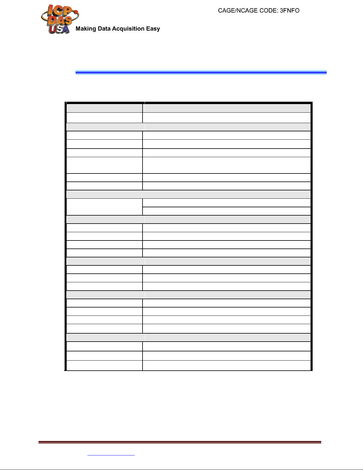
Set the dip switches to the correct positions to select the Channel, Group ID,
AP Mode, Data Format and Baud Rate that you plan to use for your SST-900B
module. Make sure that bit 8 is set for Normal Mode (0x01)
There is a example as following below.
6
7 8 9A
6
78 9A
ON
5
B5
B
4
C4
C
3 2
1
0
F
E
D
32
1
0
F
E
D
1 2 3 4 5 6 7 8
6
7 8 9A
6
78 9A
ON
5
B5
B
4
C4
C
3 2
1
0
F
E
D
32
1
0
F
E
D
1 2 3 4 5 6 7 8
Channel: 0 Group ID:
0 Broadcast/Slave
Data Format: N,8,1
Baud Rate: 115200
Mode: Normal
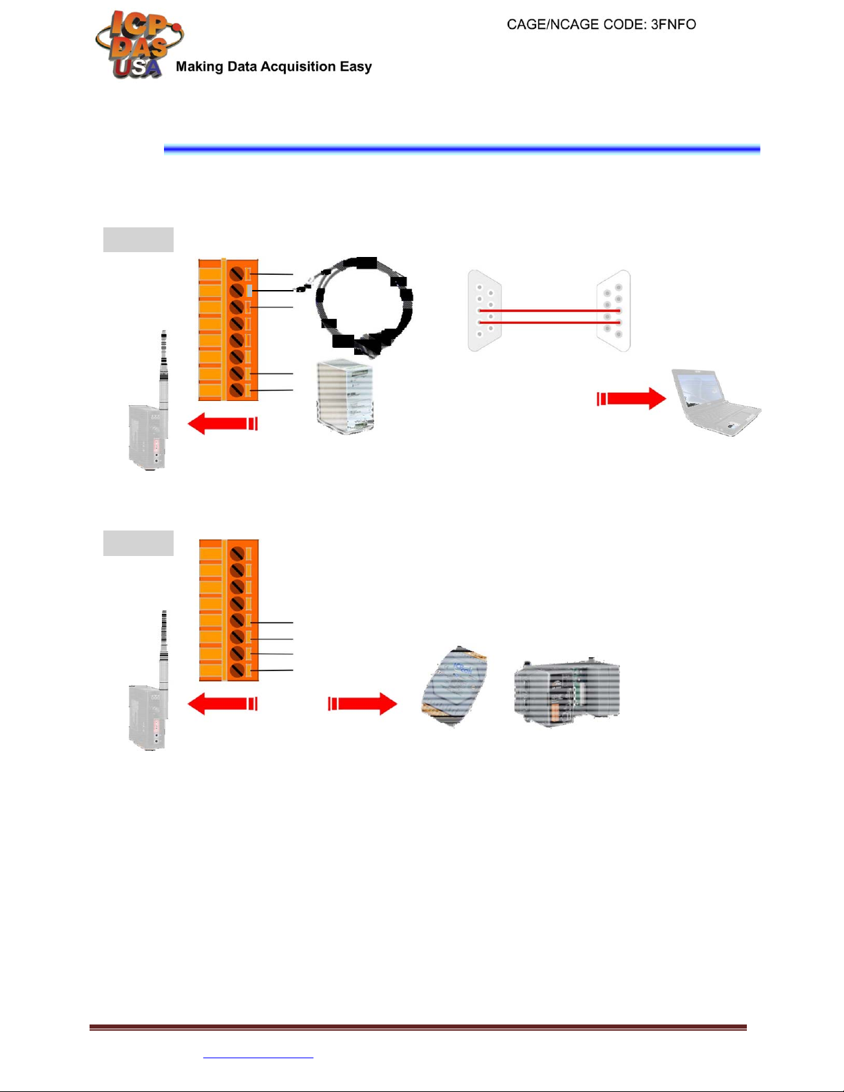
We can use any tools sending test string for simulating serial port
transmission. If the SST-900B external switch in the correctly position, we can
use the SST-900B like a real wire.
When the SST-900B sending any wireless signal, the green LED indicate will
be blinking, and so is the yellow LED indicate receiving data.

SST-900B 900 MHz RS-232/RS-485 Wireless Modem- QuickStart (Apr/2019)
ICP DAS USA, Inc. | www.icpdas-usa.com | 1-310-517-9888 | 24309 Narbonne Ave. Suite 200. Lomita, CA 90717
7
6
Appendix
Module
SST-900B
Modulation Technique
FSK (Frequency-shift keying)
Wireless
RF Channels
16
Receive Sensitivity
-100 dBm @ 150k bps
T
ransmit Power
Up to 20 dBm
Antenna
3 dBi Omni-directional antenna,
Reverse Polarity SMA (RP-SMA) Plu
g
(Male)
T
ransmission Range
1000 meters (LOS)
Maximum RF Data Rate
150k bps
Communication Interface
COM0
RS-232
RS-485
COM0 Settings
Baud Rate
1200~115200 bps
Data Bit
8
Parity Check
Even, Odd, None
Stop Bit
1
LED Indicators
Green
RF TxD
Y
ellow
RF RxD
Red
Power State
Power
EMS Protection
ESD, Surge, EFT and Hi-Pot
Required Supply
+10 VDC ~ +30 VDC
Power Consumption
0.48W
Connection
8-pin 5.08 ㎜ Removable Terminal Block
Environment
Operatin
g
Temperature
-25 ~ +75℃
Storage Temperature
-40 ~ +80℃
Relative Humidity
0~90% RH, non-condensing
This manual suits for next models
1
Table of contents