ICStation RDA5807 87-108MHz FM Radio DIY Kit
4
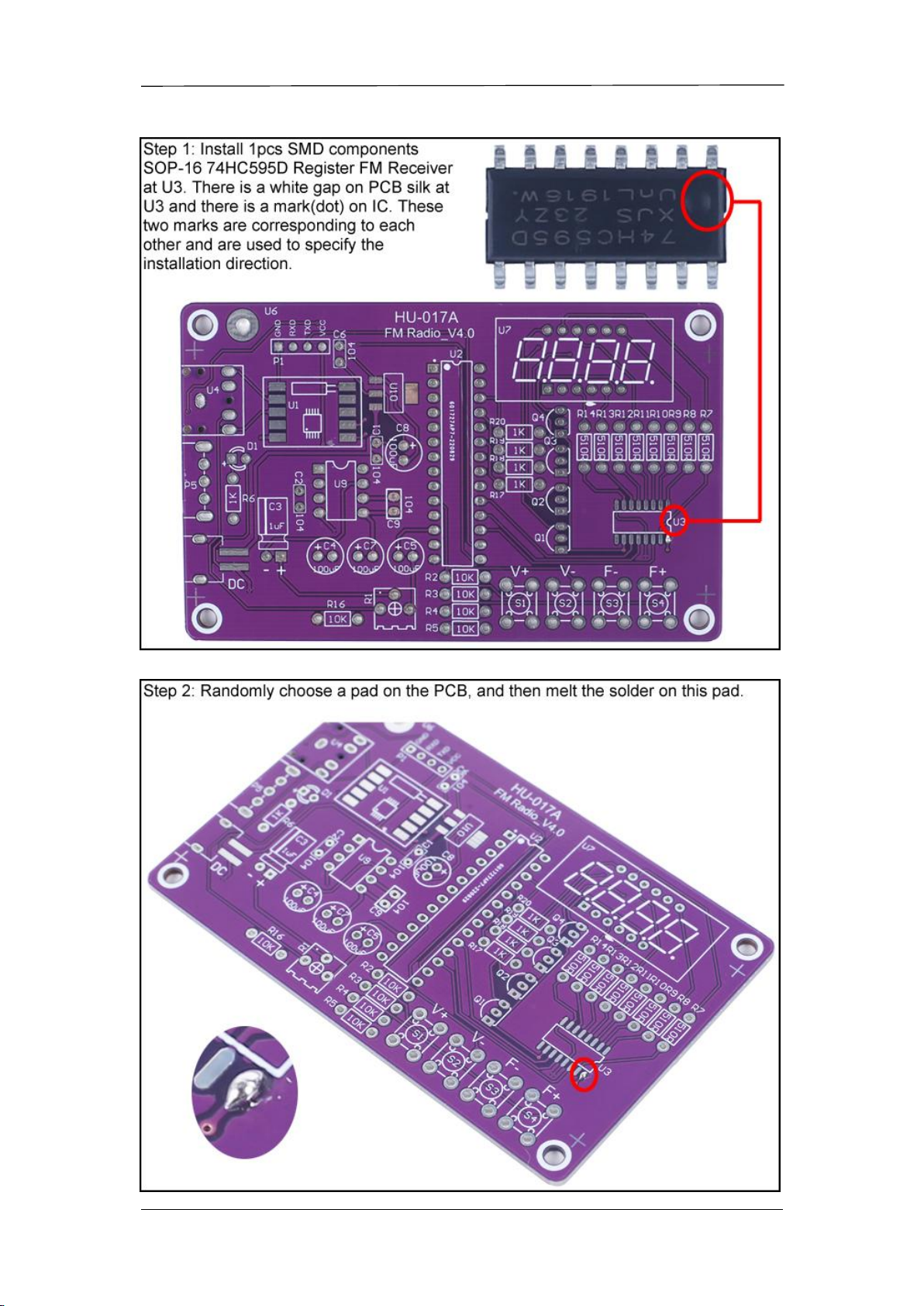
there is a gap mark on PCB silk screen where the IC Socket can place on.These two marks are
corresponding to each other and are used to specify the installation direction of the IC Socket.
12>
12>.Step 12: Install 1pcs DIP-8 IC Socket at U9.There is a gap mark on one end of the IC Socket and
there is a gap mark on PCB silk screen where the IC Socket can place on.These two marks are
corresponding to each other and are used to specify the installation direction of the IC Socket.
13>.Step 13: Install 1pcs 3mm Red LED at D1. Note: The longer pin connect to ‘ + ’ pad.
14>.Step 14: Install 4pcs 0.1uF 104 Ceramic Capacitor at C1,C2,C6,C9.
15>.Step 15: Install 1pcs 3.5mm AUX Audio Socket at U4.
16>.Step 16: Install 1pcs Toggle Switch at P5.
17>.Step 17: Install 4pcs 100uF 16V Electrolytic Capacitor at C4,C5,C7,C8. Pay attention to
distinguish between positive and negative.The Longer pin is positive pole.
18>.Step 18: Install 1pcs TO-92 S8550 Transistor at Q1-Q4. Pay attention to the installation direction.
The arc on the PCB corresponds to the arc of the components.
19>.Step 19: Install 1pcs 4Bit Red Digital Tube at U7.Pay attention to the installation direction of the
decimal point.
20>.Step 20: Install 1pcs 1uF 50V Electrolytic Capacitor at C3.Pay attention to distinguish between
positive and negative.The Longer pin is positive pole. Note: The capacitor needs to be placed horizontally,
keep a distance of 2mm between the capacitor and the PCB when installing.
21>.Step 21: Install 1pcs 200Kohm Potentiometer at R1.
22>.Step 22: Install 4pcs 6*6*8mm Black Button at S1-S4. Ensure that the buttons are installed
vertically to avoid affecting the next installation of acrylic plates.
23>.Step 23: Install 1pcs DIP-28 STC15W404AS MCU at U2.There is a gap mark on one end of the
IC and there is a gap mark on DIP-28 IC Socket where the IC can place on.These two marks are
corresponding to each other and are used to specify the installation direction of the IC.
24>.Step 24: Install 1pcs DIP-8 TDA2822M Amplifier at U9.There is a gap mark on one end of the IC
and there is a gap mark on DIP-8 IC Socket where the IC can place on.These two marks are
corresponding to each other and are used to specify the installation direction of the IC.
25>.Step 25: Install 1pcs Red/Black wire to 0.5W 8ohm Speaker.
26>.Step 26: Connect 0.5W 8ohm Speaker to PCB.
27>.Step 27: Fix FM Radio Antenna at U6 on PCB back by M2*6mm Screw and M2 Nut. Then use a
large amount of solder tin to cover the screw and nut to ensure that the antenna will not fall off during
use.
28>.Step 28: Connect AA*2 battery box to PCB. Red wire to ‘ + ’ pad.
29>.Step 29: Paste the speaker and battery box on the PCB back with double-sided adhesive tape,
and pay attention to the white line area on the PCB to define their positions.
30>.Step 30: Fix 4pcs M3*8+6mm Nylon Column Screw on PCB by 4pcs M3 Nut.
31>.Step 31: Tear off the protective film on the surface of the acrylic shell.
32>.Step 32: Fix Bottom Acrylic Board by 4pcs M3*5mm Screw.
33>.Step 33: Place 4pcs Side Acrylic Board.
34>.Step 34: Fix Top Acrylic Board by 4pcs M2*22mm Screw and 4pcs M2 Nut.
35>.Step 35: Connect to power supply and enjoy the effect.