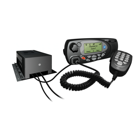
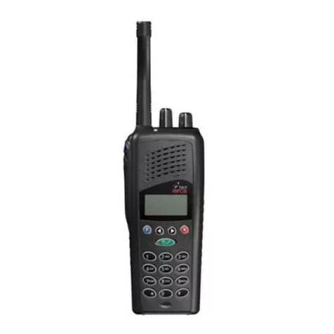
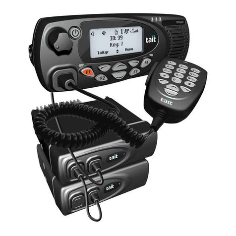
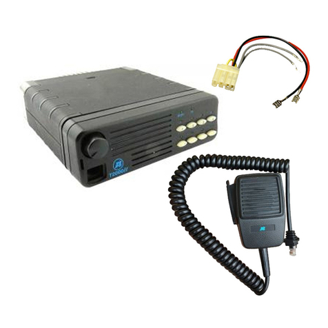
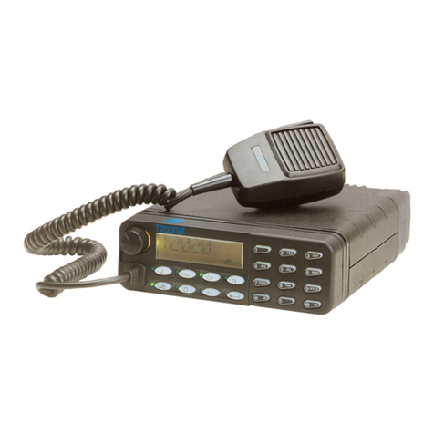
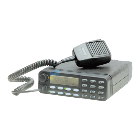
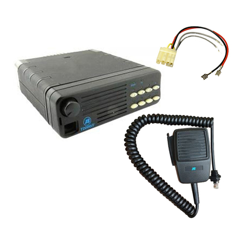
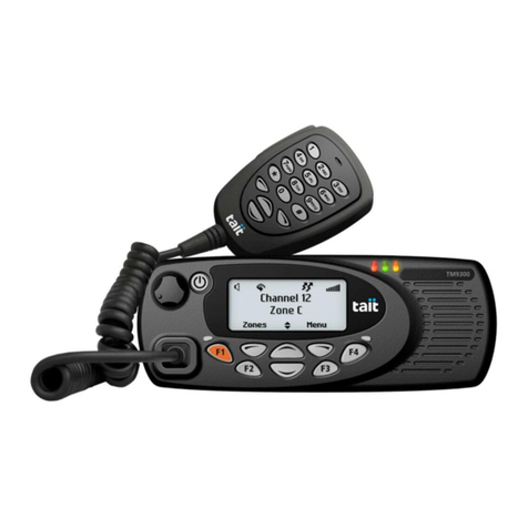
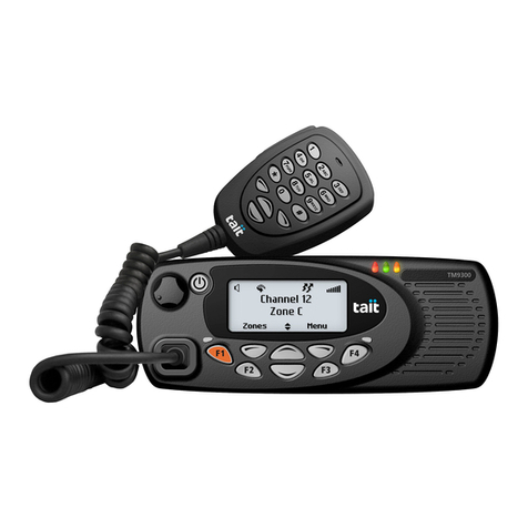
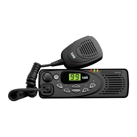
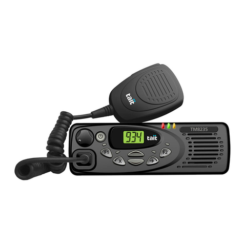
TAIT T500 RADIO
First thing to do is put the radio on to the ench and look around to the ottom of the radio
and see the two recessed screws in the ottom of the set with the radio microphone
nearest to you you will see the screws a out half an inch from the front panel, these can
now e removed from the radio these should e pozidriv and a out 1/4 of an inch in
length, once these are removed ease the ottom of the radio at the front up slowly tilting it
ackwards as the ack will still e secure to the set in some grove set in to the heat sink at
the rear of the radio, now slide The ottom panel slowly forward and you should e left
with 2 wires still connected to the oard Yellow and Black going to the Speaker remove
these very carefully remem ering were they go. If the radio has a CTCSS oard in it you
will see this to then left of the radio. Undo the screw holding this and ease the CTCSS
oard up with your fingers and put on the ench as you will not need this oard for this
conversion. To the front right of the set you will see a small oard with lots of diodes on it
and you will now have to remove this oard and looking at the truth charts decide with
frequencies you wish to put on your radio you will see that these are la elled (N9 8 7 6 5 4
3 2 1 0 A5 4 3 2 1 0) if you look at the truth chart you will see how to program these lines.
Once you have chosen the frequency's that you require and programmed the n code the
next step is to set the VCO and this can e done very ease as well what you will need for
this is your power supply and volt meter and dummy load and power meter. When
operating the Tait on frequencies elow 150MHz, connect C204 (2p7) in circuit y shorting
the pads of LK-1
RX Alignment
1. Connect power supply the radio making sure of the polarity efore turning on.
2. Connect the power meter and dummy load to the RF out put of the radio
3. Now connect you Volt meter to TP2 centre pin and check for 4-volts this is situated
a out 1/4 on inch ehind this diode oard you have just put ack in to the radio.
4 You can now a just CV208 for RX 4 volts and this is the left one of the two
capacitors in the metal can just ehind the test point and is marked RX and TX a
just the RX first and then go in to tx mode y depressing the PTT and a just CV210
for 4 volts as well,you will fine that power has come up very well to pro a ly a out
20-25 watts already.
5. You can now check your tx freq and a just L30 which is situated to the front of the
radio under the diode oard and can e adjusted through the small gap. Once the
desired freq is achieved you can now move on to the RX side of the project.
RX Alignment
With RX side you will now have to disconnect the power meter and dummy load and
connect a signal generator to the out put and set this for a out 200rnV and adjust L19 L15
L13 L12 L10 reducing the sig gen as you hear the signal increase until you have reduce it to
a out 0.1mV. You will need to go through this process several times until the desired
sensitivity is acquired and you’re happy.
Setting the deviation is not a pro lem as this can e done y adjusting RV79 to the left of
the radio a 1/3 of the way down.
One last thing I have not mentioned is there is a 90sec time out if you are like me and like to
waffle l this might e a good idea to leave this in place if you do wish to remove it then give
me a call and I will let you know how to do this.
Happy conversions rom G0WFQ Malcolm malcolm.troy@virgin.net

