ICWUSA.com, Inc.
If you have any questions, please call 1-800-558-4435
MD ARM INSTALLATION INSTRUCTIONS
MD ARM INSTALLATION INSTRUCTIONS - rev 11/13/2012 mf
page 1
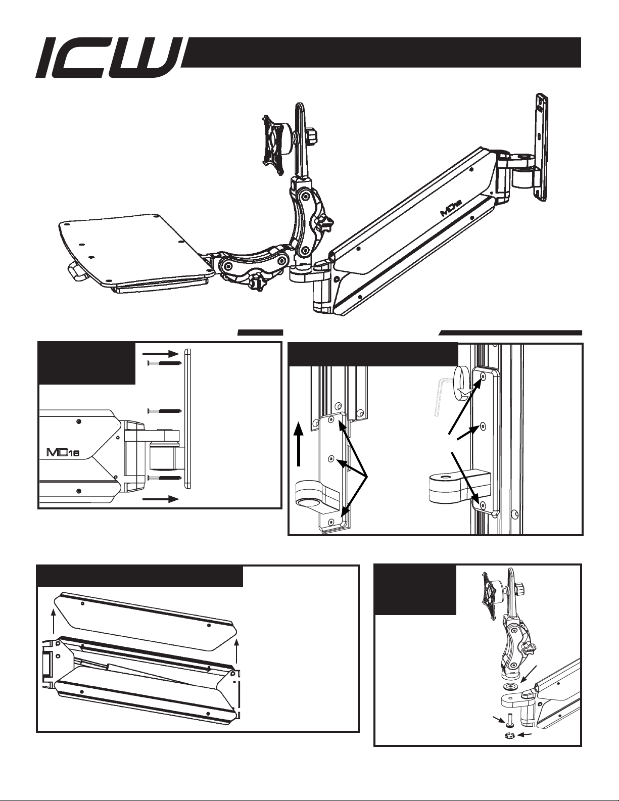
ATTACH MD
WALL MOUNT
Locate a stud in a
wall you intend to
mount your arm on.
Mark the top hole,
drill 11/64 pilot hole
and insert an ICW
provided #14 screw
and tighten slightly.
Using a level, mark
the 3 lower holes and
drill pilot holes, insert
the last three #14
screws and with the
mount level, tighten
all screws securely.
Lift the wall
mount up to
the bottom
of the TMD
track, or lower
over the top
of the track if
easier. Slide
the clamp
plates into the
groove in the
TMD track.
Track
clamp
plates
Once the
wall plate is
at the height
that you
want it, use
the 5/32 hex
key to lock it
into place by
turning the
3 clamping
screws in
to place
clockwise.
Clamp
screws
ATTACH WALL PLATE TO TRACK
IF MOUNTING DIRECTLY TO WALL IF MOUNTING TO TRACK
ATTACH
PARALINK
TO MD ARM
Attach the Paralink to
MD arm using 3/8 bolt
assembly and 1” bearing
assembly provided. Insert
bolt assembly up through
ear at end of arm. Place 1”
bearing assembly over bolt
on top of ear. Place Paralink
over bolt and bearing and
turn bolt until Paralink is
secure and smoothly turns
against the bearing. Beauty cap
3/8 bolt
1” bearing
REMOVE COVERS FROM MD ARM Using a Phillips head
screwdriver, remove the four
screws from the upper cover,
exposing the cable channel.
WARNING - PINCH POINT:
Keep fi ngers away from
the inner arm area where
the gas spring is located.
The lower cover can also
be removed by lowering the
arm into the down position,
removing the screws and
sliding the cover forward off
of the arm.


