ID Photonics CoBrite Series User manual

800.887 .5065
©


______________________________________________________________________
CoBrite User Manual
2
Content
1General Information............................................................................................................3
2Unit Overview –Operating principle and block diagram......................................................7
3Quick Start –Remote Control...........................................................................................13
4Getting Started .................................................................................................................14
5Description of front panel operation CoBriteDX.................................................................19
6Description of instrument operation using the Web GUI....................................................24
7Remote Control ................................................................................................................28
8Copyright..........................................................................................................................41

_____________________________________________________________________
3
CoBrite User Manual
1General Information
1.1 Warning Laser Safety
The laser sources specified by this user guide are classified according to IEC 60825-1 (2007)
Laser Notice No. 50 dated 2007-June-24 and comply with CFR 1040.10 except deviations per
Laser Notice No. 50, July 2001 Key Feature Number 4.
This device is a Class 1M laser product for use only under the recommended operating
conditions and ratings specified in this document. Use of controls or adjustments or
performance of procedures other than these specified in this product datasheet may result in
hazardous radiation exposure.
Do not view the laser output from this device directly with optical instruments (e.g., eye loupes,
magnifiers, microscopes). Viewing the laser output with certain optical instruments within a
distance of 100mm may pose an eye hazard. The class 1M laser product definition is based on
all conditions defined in this section.
Please pay attention to the following laser safety warning: Under no circumstances look into the
end of an optical cable attached to the optical output when the device is operational. The laser
radiation can seriously damage your eyesight. Do not enable the laser when there is no fiber
attached to the optical output connector. The laser is enabled by pressing the ’Laser on’ button
in the operating software delivered with the instrument. The laser is on when the red LED on the
front panel of the instrument is lit. The use of optical instruments with this product will increase
eye hazard.
In doubt about laser safety requirements consult a trained laser safety instructor for local safety
requirements of this product.
1.2 Compliance Statement Electromagnetic Compatibility and device safety
Hereby, we confirm that the system has been demonstrated and audited for compliance for the
following directives.
1.2.1 International
IEC 60950-1:2005, modified+Cor.:2006 + A1:2009, modified
CISPR 11:2003 in accordance with EN 61326-1: 2006
1.2.2 United States of America
FCC 47 CFR Part 15, Subpart B Class A, Measurement process ANSI C63.4 (2009)
1.2.3 European Union
EN 55022:2011
EN 61326-1: 2006
EN 61000-6-2: 2006
EN 61000-6-4: 2011
EN 61000-3-2: 2010
EN 61000-3-3: 2009
1.3 Limitation of communication interfaces
Operation of all USB Ports is limited to a maximum cable length of 3m and a maximum length of
30m for all Ethernet ports present.
1.4 European WEEE Directive Compliance
ID PHOTONICS has established processes in compliance with the Waste Electrical and
Electronic Equipment (WEEE) Directive, 2002/96/EC. This product should not be disposed of as
INVISIBLE LASER RADIATION
DO NOT VIEW WITH
OPTICAL INSTRUMENTS
CLASS 1M LASER PRODUCT
(IEC 60825-1/2007)

______________________________________________________________________
CoBrite User Manual
4
unsorted municipal waste and should be collected separately and disposed of according to your
national regulations. In the European Union, all equipment purchased from ID PHOTONICS can
be returned for disposal at the end of its useful life. ID PHOTONICS will ensure that all waste
equipment returned is reused, recycled, or disposed of in an environmentally friendly manner,
and in compliance with all applicable national and international waste legislation. It is the
responsibility of the equipment owner to return the equipment to ID PHOTONICS for appropriate
disposal. If the equipment was imported by a reseller whose name or logo is marked on the
equipment, then the owner should return the equipment directly to the reseller. If you have
questions concerning disposal of your equipment, contact ID PHOTONICS’s at WEEE@id-
photonics.com.
1.5 Line Voltage Selection
CoBrite Mainframes operate from any single-phase AC power source that supplies 100 ~
240VAC at a frequency at 50/60 Hz. The input line voltage setting is done automatically by
CoBrite power supply.
1.6 Service
Do not attempt to service or adjust this instrument unless an authorized person is present. Do
not install substitute parts or perform any unauthorized modifications to this instrument. Contact
ID Photonics or your local distributor to obtain service support.
1.7 Help and User feedback
ID Photonics GmbH is dedicated to continuously improve customer experience of our products.
Thus, if you have any feedback that might help us to improve our products send us an E-Mail to:
feedback@id-photonics.com
1.8 Optical output of Laser Ports
Each laser port features a polarization maintaining Fiber output which can be both used with
standard single mode fibers and polarization maintaining fibers. The emitted E-field is oriented
along the slow axis of the fiber.
1.9 Safety
1.9.1 General Safety Precautions
The following general safety precautions must be observed during all phases of operation of this
instrument. Failure to comply with these precautions or with specific warnings elsewhere in this
manual violates safety standards of design, manufacture, and intended use of the instrument.
ID Photonics assumes no liability for the customer’s failure to comply with these
requirements.
Before operation, review the instrument and manual for safety markings and instructions. You
must follow these to ensure safe operation and to maintain the instrument in safe condition.
Slow Axis
Stress Rods
Connector Key

_____________________________________________________________________
5
CoBrite User Manual
1.9.2 General
This product is a Safety Class 1 instrument (all units except CoBrite DX1, provided with a
protective earth terminal). The protective features of this product may be impaired if it is used in
a manner not specified in the operation instructions.
1.9.3 Environment Conditions
This instrument is intended for indoor use in an installation category II, pollution degree 2
environments. It is designed to operate at a maximum relative humidity of 95% and at altitudes
of up to 2000 meters.
Refer to the specification tables for the ac mains voltage requirements and ambient operating
temperature range.
Note: Before connecting electrical power to the unit, make sure the unit could
acclimatize to ambient temperature for at least 2 hours to avoid damage by i.e.
condensed humidity on electrical parts inside the unit.
1.9.4 Fuse Replacement
For continued protection against the possibility of fire, replace the fuse only with a fuse of the
specified voltage, current and type ratings.
1.9.5 Before Applying Power
Verify that all safety precautions are taken. The power cable inlet of the instrument serves as a
device to disconnect from the mains in case of hazard. The instrument must be positioned so
that the operator can easily access the power cable inlet. When the instrument is rack mounted
the rack must be provided with an easily accessible mains switch.
1.9.6 Maximum ratings
ALWAYS operate the unit within the maximum ratings. Ignoring these limits may result in
permanent damage to the unit and loss of warranty.
1.9.7 Ground the Instrument
(this section does not apply to DX1 type chassis)
To minimize shock hazard, the instrument chassis and cover must be connected to an electrical
protective earth ground. The instrument must be connected to the ac power mains through a
grounded power cable, with the ground wire firmly connected to an electrical ground (safety
ground) at the power outlet. Any interruption of the protective (grounding) conductor or
disconnection of the protective earth terminal will cause a potential shock hazard that could
result in personal injury.
1.9.8 Do Not Operate in an Explosive Atmosphere
Do not operate the instrument in the presence of flammable gases or fumes.
1.9.9 Do Not Remove the Instrument Cover
Operating personnel must not remove instrument covers. Component replacement and internal
adjustments must be made only by qualified personnel.
Instruments that appear damaged or defective should be made inoperative and secured against
unintended operation until they can be repaired by qualified service personnel.
Opening the instrument will result in loss of all warranty given for the instrument and may exhibit
lethal health risks.
Keep away from live circuits inside the equipment. Operating personnel must not remove
equipment covers. Only factory authorized service personnel or other qualified service
personnel may remove equipment covers for internal subassembly or component replacement
or any internal adjustment. Do not install substitute parts or perform any unauthorized
modification of the equipment or the warranty may be voided.
1.9.10 Ventilation
Keep a space of 30 cm or more between the rear side of the device and any other objects such
as walls to guarantee sufficient cooling of the device.

______________________________________________________________________
CoBrite User Manual
6
Never block the air fan and ventilation openings.
1.9.11 Cleaning the Instrument
To avoid personal injury, power down the device and disconnect it from line voltage before
performing any of the following procedures.
To clean the exterior surface, perform the following steps:
Remove loose dust on the outside of the instrument with a lint-free cloth.
Use a soft cloth dampened with water to clean the device. Use 75% isopropyl alcohol
solution as a cleaner. Do not use any abrasive or chemical cleaning agents.
1.9.12 Safety Symbols on Instruments
1.9.12.1 Warning or Caution
If you see this symbol on the product, you must refer to the manuals for specific Warning or
Caution information to avoid personal injury or damage to the product.
1.9.12.2 ESD Safety Warning
This sign indicates that the respective modules, boards or RF inputs and outputs are
susceptible to damage by electro static discharge (ESD), and require proper protection
procedures for storage and handling.
1.9.12.3 Output of Laser Radiation Warning
This sign does indicate a source of optical radiation that may emit close to the location this label
is present. Follow according laser safety procedures as listed below and defined in general rules
at all times.
1.9.12.4 Wear Eye Protection
Wear eye protection if exposure to high-intensity rays or laser radiation exists according to
Laser safety rules and best practices.
1.9.12.5 Do Not Directly View Optical Laser Port Output
Under no circumstances should you use any optical instruments to view the optical laser port
output directly.

_____________________________________________________________________
7
CoBrite User Manual
1.9.12.6 Precautions with Connectors
It is essential to ensure that all optical connectors are in good condition. Dirty connectors can
lead to poor performance, while broken connectors can cause damage to other equipment!
Before an optical connector is used, check it visually by using an optical microscope as
recommended by the manufacturer of the connector. If the connector needs to be cleaned,
apply the cleaning procedure recommended by the manufacturer of the connector.
Make sure you are familiar with these issues to avoid damage to your device and possible
violation of warranty. Important!
Before connecting the inputs or outputs to any measurement equipment or device under test,
make sure that a suitable attenuator, if necessary, is fitted.
2Unit Overview –Operating principle and block diagram
2.1 CBDX

______________________________________________________________________
CoBrite User Manual
8
2.2 CBDX2
CoBrite is tunable laser instrument series capable of hosting up to 4 tunable laser ports that can
be independently controlled. The series shares the same software and control architecture as
well as the same portfolio of laser variants.
The CoBriteDX variant features a local touch panel display and supports up to 4 laser ports.
The more compact CoBriteDX2 supports up to 2 laser ports and is controlled remotely via the
installation free browser-based GUI.
Different laser types are offered allowing users to adapt for various use cases such as coherent
transmission, EDFA testing and insertion loss profile measurement.
User data transfer is provided via a SCPI interface utilizing USB and Ethernet interfaces. The
unit supports multiple user connections and multiple user access right level administration. The
user interface does not require any specific API Software or similar to be installed on host
computers while providing a standardized communication protocol so that any user environment
is able to communicate with unit.
The unit provides a built-in webserver that allows the control of the unit via any device such as
PCs or smartphones that are able to run a Web Browser.
Using USB; the device provides a virtual Ethernet interface allowing to access the unit via
browser or a telnet session. Additionally, a virtual COM port for straightforward serial access
and a virtual Mass storage device (USB Stick) is installed providing access to the manual,
programming examples and drivers.
The unit provides hardware triggers allowing triggering Laser setting executions as well as
indication of laser tuning events.
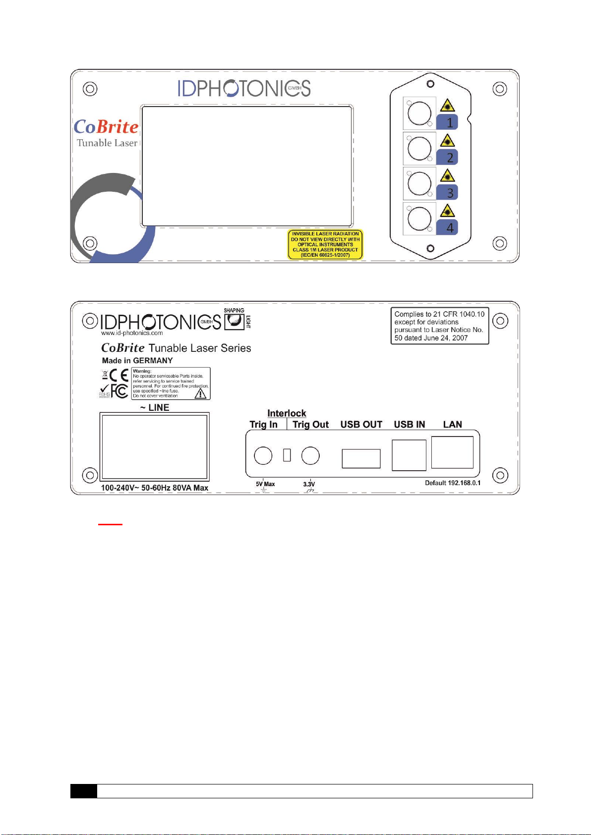
2.3 CBDX –Front side of unit
The front side is dominated by a large Touch Panel Color Display for intuitive control of the
instrument. The optical connector plate type depends on the laser configuration equipped on the
specific unit. The 2 screws allow to easily detach the front plate to allow removal and cleaning of
the connector.
Note The fibers attached to the plate are 250um buffered type and therefore sensitive to
breakage under mechanical stress. So, take care if removing the connector plate to
not damage optical fibers.
_____________________________________________________________________
9
CoBrite User Manual
2.4 CBDX –Rear side of unit
The rear side hosts electrical connectors that can be utilized by the user.
Note This unit contains a fan for forced air cooling. The inlet and outlet are slits located at
the sides of the unit. Never block these areas to avoid overheating and failure of the
unit.
2.4.1 Power socket
Electrical power is supplied using a VDE 0625, EN 60 320, C13 type electrical connector. Only
use the supplied cable or an identical cable that conforms to the aforementioned standard to
connect to the unit. The unit automatically adapts to local power line specifications within the
range printed on the unit.
______________________________________________________________________
CoBrite User Manual
10
2.5 CBDX2 –Top side of unit
Note This unit utilizes the top cover for heat dissipation of internal components. Do not
reduce the thermal dissipation by blocking the airflow in this area by placing items
on it to avoid overheating of the unit.
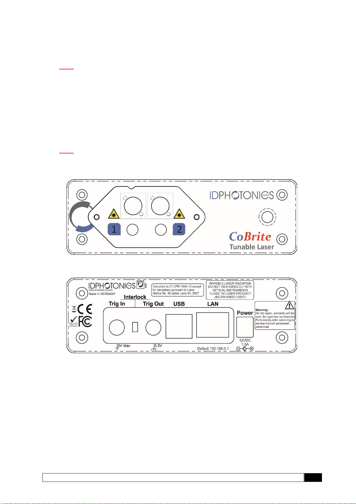
2.6 CBDX2 –Front side of unit
The front side is dominated by a large Touch Panel Color Display for intuitive control of the
instrument. The optical connector plate type depends on the laser configuration equipped on the
specific unit. The 2 screws allow to easily detach the front plate to allow removal and cleaning of
the connector.
Note The fibers attached to the plate are 250um buffered type and therefore sensitive to
breakage under mechanical stress. So, take care if removing the connector plate to
not damage optical fibers.
2.7 CBDX2 –Rear side of unit
The rear side hosts electrical connectors that can be utilized by the user.
2.7.1 Power socket
Electrical power is supplied using a coaxial 12V DC jacket. Only use the supplied external
AC/DC adaptor to power the unit. The AC/DC adapter unit automatically adapts to local power
line specifications within the range and complies to standards printed on the adaptor.
2.8 CoBrite series - Common Ports
2.8.1 Trigger Ports
The SMA type sockets can be used to achieve timewise synchronization of the CoBrite with
other equipment. Both ports support 3.3V LV TTL standardized signals.
Trigger IN allows triggering tunable laser setting if the feature is enabled via Remote control or
GUI. Polarity and user set delays can be also configured this way. For positive polarity, the scan
is started with the positive flank und will be fully executed regardless of the trigger in status
afterwards. For negative polarity, the scan is triggered by the negative flank on the unit.

_____________________________________________________________________
11
CoBrite User Manual
Each laser port installed on the chassis can be en- or disabled to be considered for the H/W
trigger input using the command “TRINACT”. All considered ports are will only start to tune if a
new setting has been set via software once the trigger in port has been initiated.
Note: Per default, “trigger tuning” for all Lasers are disabled. Use SCPI commands to alter
configuration.
Trigger OUT provides an output signal indicating periods at which the one or more laser ports
are tuning. The polarity of the signal and the logic of the signal can be changed via Remote
control or GUI.
Each laser port installed on the chassis can be en- or disabled to be considered for the H/W
trigger output using the command “TROUTACT”. All considered ports are combined via a logical
“OR” for the tuning active true state.
Note: Per default, “tuning active” signals of all Lasers are considered for the joint trigger
out.

______________________________________________________________________
CoBrite User Manual
12
2.8.2 Interlock
Removing the interlock jumper disables the laser optical output. Note that the lasers will be
disabled regardless of any software setting and cannot be overridden by software as this jumper
directly acts on the laser hardware itself. The interlock status is indicated on the front panel(DX)
as well as via remote software readout query.
2.8.3 Data Ports
Ethernet –The RJ45 jacket is used to connect the unit to Ethernet networks based on the IEEE
802.3 standard. Per factory default, the unit is set to a fixed IP Address 192.168.0.1. The IP
address configuration can be changed via Remote control or GUI. We recommend to initially
connecting via USB to set up the Ethernet interface first.
See section 4.2.3 for details on how to establish an application layer connection to remote
control the unit.
USB IN –The USB 2.0 type B jacket is used to connect the unit a host computer to be able to
operate the supplied GUI or perform remote control on the unit. See section 0 for details on how
to establish an application layer connection to remote control the unit.
USB OUT –The USB 2.0 type A jacket is intended for future use and serves no functionality at
this point.
2.9 Optional Accessories
2.9.1 Single 19” Rackmount Adaptor CBDX-19-1
This adaptor is used to mount one CoBriteDX chassis in a standardized 19” Rack in a 2 HE slot.
2.9.2 Single 19” Rackmount Adaptor CBDX2-19-1
This adaptor is used to mount one CoBriteDX2 chassis in a standardized 19” Rack in a 1 HE
slot.
2.9.3 Single 19” Rackmount Adaptor CBDX-19-2
This adaptor is used to mount two CoBriteDX chassis in a standardized 19” Rack in a 2 HE slot.
2.9.4 Single 19” Rackmount Adaptor CBDX2-19-2
This adaptor is used to mount two CoBriteDX2 chassis in a standardized 19” Rack in a 1 HE
slot.
For mounting instructions, see the separate guide which is supplied in case you have ordered
these accessories or open the corresponding PDF on the USB stick or download it via the Web
Interface of the instrument.

_____________________________________________________________________
13
CoBrite User Manual
3Quick Start –Remote Control
This section contains redundant information from other chapters but is useful for a first-time
usage of the instrument.
1. Power up the unit using the main power switch located at the back of the unit
2. Wait until the boot sequence is completed. The local screen should look similar to
this (DX)
3. Connect the USB Port located at the rear of the unit to your Windows10 PC or
connect the Ethernet Port to your LAN.
a. For USB based access, all drivers will be installed automatically, Windows
device manager should show now 3 devices:
1. A storage device containing manual etc.
2. A virtual Ethernet Interface “RNDIS”
3. A virtual COM Port
Both virtual COM and Ethernet Ports can be used to remote control the unit.
The installed COM Port number can be retrieved from Windows device
manager. The IP address by the command shell “ping cobrite.local”.
b. For Ethernet based access, the default IP of the unit is 192.168.0.1. Make
sure that the host PC IP is in the same subnet as the laser unit (192.168.0.x).
If this is not the case, you can change the IP settings of the unit via the touch
screen or using the USB Port of the unit. Use “cobrite.local” as an alternative
to the IP address to connect to the unit.
4. Open your Web browser, enter “cobrite.local” in the address field and hit <enter>.
The Webpage allowing to control the laser remotely should open now.
Note: Depending on the configuration of your host PC DNS structure, the “cobrite.local”
name representation might not be resolved into the correct IP address. In such a case, for a
DX unit, retrieve the IP Address on the local touch panel under “Device Config – Network
Config” and use it instead of the name. For a DX2 unit, open a connection to the USB
virtual serial interface and type the command “USBIPADDR?;” to retrieve the USB IP
Address or “IPADDR?;” for the IP address of the Ethernet interface.

______________________________________________________________________
CoBrite User Manual
14
4Getting Started
This section contains more in-depth information on how to setup the remote interfaces on a host
PC and basic principles of the laser.
4.1 Connection of Hardware
•Connect optical fibers to the laser output ports or make sure that no laser radiation can
be uncontrollably emitted by the unit.
•Connect the power supply of the unit using the supplied Power Cord and switch on the
unit using the switch located at the back of the unit.
•Wait for the unit to finish initializing. For DX4, the procedure is completed when the
startup screen showing the ID Photonics logo is cleared and the laser parameters are
shown. For DX1, the procedure is completed when the Power LED stops flashing. Now
proceed with Software installation as described below.
4.2 Ethernet connection
This section covers connectivity using Ethernet, skip it if you plan on using USB.
The default IP address is 192.168.0.1, DHCP off. If you plan to connect using the Ethernet
interface make sure the host PC is within the same subnet as the CoBrite Ethernet Interface
(The PC IP Address is 192.168.0.x then). The connectivity can be tested by opening a
command shell (type “cmd” in windows search field and hit <enter>, a “black window with a
DOS shell should open) and executing the command “ping 192.168.0.1”.
If you do wish to change the IP settings and do not have remote access to the unit follow either
of the following sections depending on the type of chassis:
4.2.1 CoBriteDX
Use the local touch panel and press “Device Setup”. Then press “Network setup” and configure
the interface accordingly. Note that this change will require a reboot (soft reset of the unit) to
become effective.
4.2.2 CoBriteDX2
If you do wish to change the IP settings of the unit, we recommend first connecting via USB and
changing the IP settings via USB connection.
Note that changing the IP address requires the user to be connected with user level 1 or higher.
Send the command “pass IDP” or enter the password “IDP” in the GUI to elevate the user level
to 1. This change will require a reboot (soft reset of the unit) to become effective.
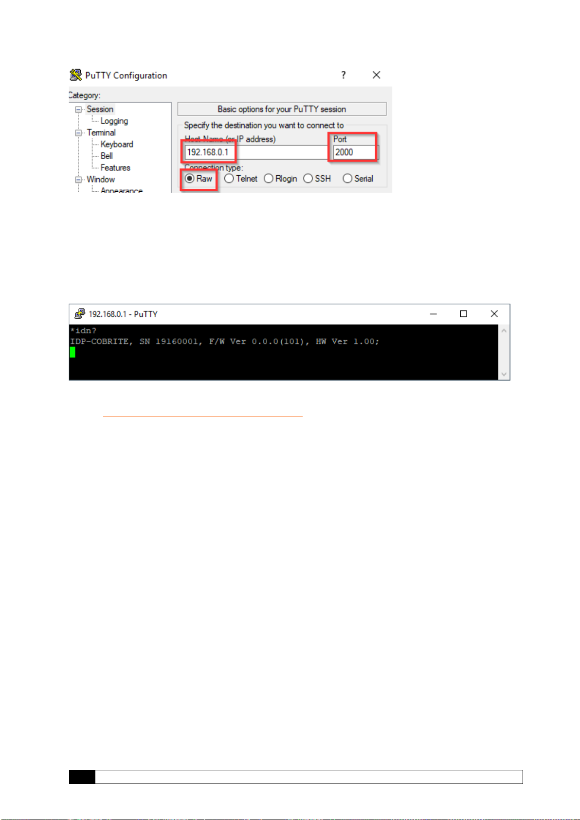
4.2.3 Opening a remote connection via Ethernet
The device supports a session based remote access on Port #2000.
Start the terminal program “putty.exe” supplied with the unit or use any other terminal program.
Set the following parameters in Putty and open the connection:
_____________________________________________________________________
15
CoBrite User Manual
Alternatively to the default IP Address shown above, enter “cobrite.local” or the IP address
currently set to the unit. If in doubt, use the touch panel display “Device config” – “IP config” to
retrieve the actual IP Address.
Note that the must be a valid route on the IP layer between the device and the host PC (i.e. the
ethernet port of the host PC is set to the same subnet as the device, for example 192.168.0.2)
must be established before continuing. Use a command shell and command “ping cobrite.local”
to test the route.
Once the connection is established, type in “*idn?” and hit <ENTER>. The unit responds with its
*idn? String.
Alternatively, a request based remote control via http Port 80 is possible. To test this, open a
browser window and type the following string into the address field:
http://cobrite.local/scpi/*idn?
For more details, see section 7.2.
4.3 USB Connection
This section covers connectivity using USB, skip it if you plan using Ethernet.
Once the unit is powered up and the USB cable is connected to the host computer for the first
time, a new device installation should be triggered automatically within Windows.
Once installation is complete, three devices are installed on the host computer:
1. Virtual Ethernet Interface
2. Virtual COM Port
3. Virtual Storage device that contains resources such as manual and programming
devices as well as drivers for Windows 7.
4.3.1.1 Windows 10
Windows 10 will automatically install 3 devices allowing to connect the unit
1. A virtual Ethernet interface (RNDIS)
2. A generic virtual COM port driver “Serial USB device”. If you have several COM ports
installed in the host PC, you may want to note the COM Port number under which the
unit got installed. For further details on USB connection, see section 4.3.1.3.
3. A storage device similar to an USB Stick containing resources for the laser unit
The virtual COM Port and the virtual Ethernet interface are concurrent ways to access the unit
for remote control. The web-based control is automatically accessed via entering “cobrite.local”
into your browser.
4.3.1.2 Windows 7
Windows 7 will install the same structure as described in the windows 10 section above. It will
automatically install a virtual Ethernet interface (RNDIS) and the USB storage device (“Linux
File- Store Gadget USB Device”). However, it does not have a preconfigured driver setup for the
virtual COM Port. It will try to locate a driver for the unit on the host PC first and then check

______________________________________________________________________
CoBrite User Manual
16
online. Stop the search and select the option “Install a custom driver”. Point the installation
routine to the driver located on the USB storage device provided by the unit in directory
“USBDriverWin7” and select file “CoBriteUSBSerialDriverWindows7.inf” in this folder. If the
installation has been completed already, open Windows Device Manager, locate “CDC Serial”,
right click on it and select “Update driver”. Proceed as described before.
Continue with the installation routine. Once installed, the virtual COM port should appear in
Windows Device Manager as shown below. The COM Port number will be different for your
system. Note down the number for later usage in remote control applications.
4.3.1.3 Connection to the device via USB via Host PC
Once installed properly, the USB connection provides a virtual COM Port and a virtual Ethernet
Port to the instrument. To access the unit via virtual Ethernet, follow the instructions as in
section 4.2.3 but note that the IP Address of the unit will be different as for the physical Ethernet
Port.
To access to the unit using the virtual COM port, open a terminal window using the installed
COM port number per description above.
4.4 Installation of Control Software
This instrument does not require any installation of software for operation. Once connected to a
host PC or a local network, simply enter “cobrite.local” into the address field of your Web
browser to access the unit.
4.5 What if “Cobrite.local” cannot be reached by host computer?
Depending on the configuration of your host PC DNS structure, the “cobrite.local” might not be
resolved into the correct IP address. In such a case, for a DX unit, retrieve the IP Address in
local Touch display under “Device Config – Network Config” and use it instead of the name or
use the following method described for DX2 units.
Note that there are 2 IP addresses shown, one for the physical Ethernet interface (Network
Interface) and one for the virtual Ethernet interface installed via USB.For a DX2 unit, open a
connection to the virtual serial interface and type the command “USBIPADDR?;” to retrieve the
IP Address for USB connection and “IPADDR?;” for physical Ethernet.
After retrieving the address, enter the corresponding IP address into your browser address field
to access the unit.

_____________________________________________________________________
17
CoBrite User Manual
4.6 Laser modes
Coarse tuning allows accessing the full specified tuning range while fine tuning (FTF) allows for
offsetting from the coarse tuning set point by a small range. The resulting set point is the sum of
coarse tuning set point and FTF/fine tuning value.
4.6.1 Coarse tuning
This tuning mode allows tuning the laser to any frequency of the available range specified for
the laser port. The tuning process will require the output to be disabled for a short period of
time.
Description of tuning process:
1. Output will be switched off (~1 second)
2. Output is switched on using new frequency
3. Power is increased until final output power is reached. Maximum tuning times for this
step differ from laser type to laser type.
4. Power is stabilized, tuning process is completed.
Note that the time to tune the laser is the actual time required to tune the laser, the software
based tuning indicator may indicate a tuning state for a longer time period than the actual tuning
requires.
4.6.2 Fine tuning (FTF)
Fine tuning allows detuning the laser within a small range from the target frequency set using
the coarse tuning parameter. The laser will detune to the target setting with output power on
during the tuning process which changes the output frequency in a linear ramp.
1. –Tuning is triggered
time
Power
time
Frequency
Wavelengt
1
2
3
4
f
fmax
fmin
1. Coarse tuning setpoint
2. fine tuning range
f
fmax
fmin

______________________________________________________________________
CoBrite User Manual
18
2. Tuning process taking ~1second per GHz. Power remains constant –Power remains
constant
3. Laser settles on new value
1
2
time
Power
time
Frequency
Wavelength
3

_____________________________________________________________________
19
CoBrite User Manual
5Description of front panel operation CoBriteDX
After the device has initialized, the front panel will look as depicted below:
(1) The central main field displays key parameters defining the current optical status of a
laser selected by the right-hand tab. Touch on any of the parameters to change them.
(2) The right-hand side tabs display the laser ports installed in the unit indicating
on/off/tuning status by the background color, current wavelength/frequency and optical
output Power. Touch a tab briefly to select the laser to display details in the central main
field. If the tab is pressed for a longer time, an increasing red progress bar will be
displayed. If at 100%, the laser will be toggled on if previously off or vice versa. A
flashing background indicates that the laser is currently tuning.
(3) Pressing “Settings Laser x“ will open a pop up allowing to change parameters of the
selected laser.
(4) “Device Setup” allows changes to the chassis set up such as IP configuration, base unit
wavelength/frequency etc. See below for details.
(5) “Switch on/off all lasers” will simultaneously en- or disable the laser output power.
The red “Remote” indicator will only be displayed if one ore more remote connections are active.
“Interlock” will only be displayed if the hardware laser safety jumper located at the rear of the
unit has been removed. In this state, all lasers are disabled and can only be switched on again if
the jumper is installed again.
“Error” will only be displayed in case of active errors present.
The screenshot below is taken in a regular operational state with 4 Laser outputs switched on.
Laser 1 is selected
To enable or disable the laser output, touch the laser selection button for about 1 second. If the
laser status is off, the field will start to fill red. Once the field is filled, the laser will be switched
on and vice versa for switching the laser off. The same method applies to the “All Lasers
On/Off” button.
Other manuals for CoBrite Series
1
This manual suits for next models
4
Table of contents
Other ID Photonics Measuring Instrument manuals

Popular Measuring Instrument manuals by other brands

PCB Piezotronics
PCB Piezotronics IMI SENSORS M621C40 Installation and operating manual

LTH Electronics
LTH Electronics BMD17 Operation guide

Rosemount
Rosemount 5401 Reference manual

Hanna Instruments
Hanna Instruments HI 96753C instruction manual

Macnaught
Macnaught MX Series manual

gefran
gefran KH-SIL2 Series Manual of Electrical Installation


