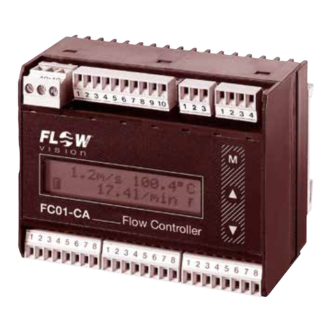
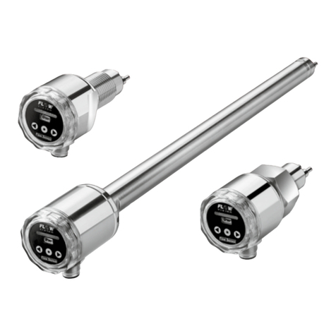
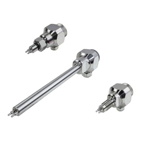
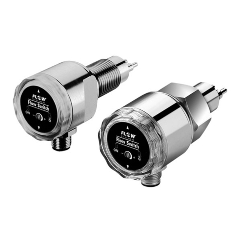
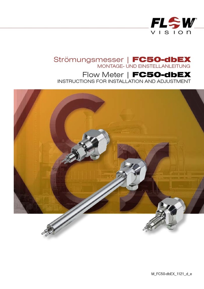
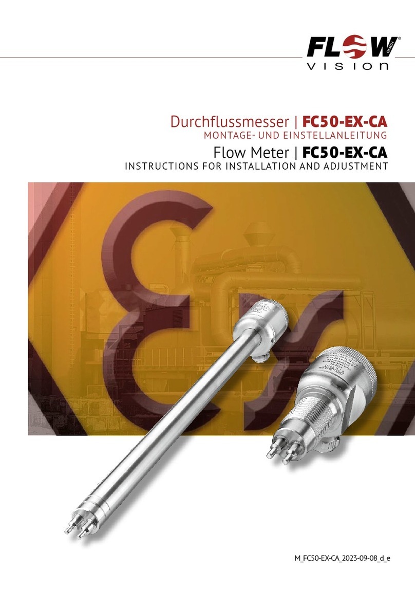
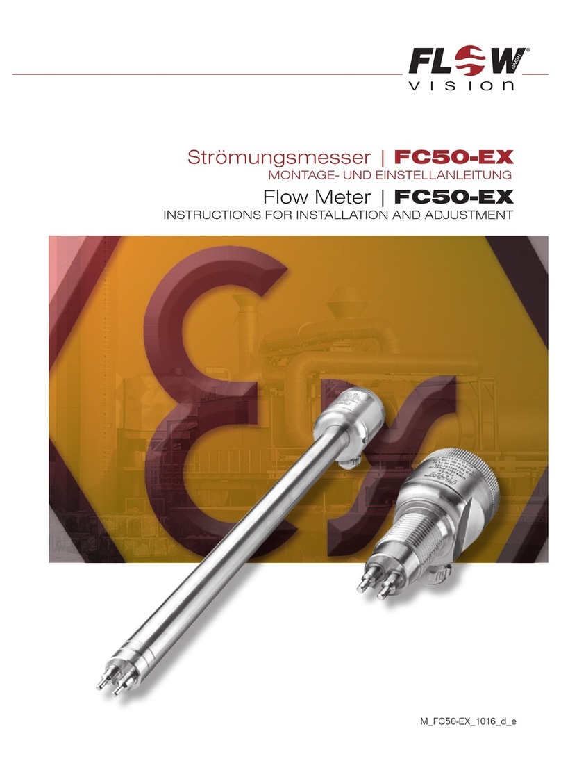
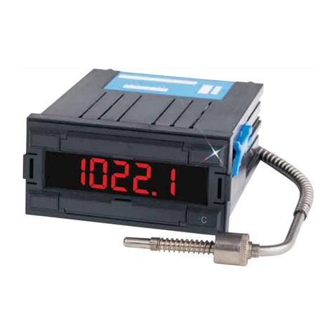
Flow vision FC01-Ex Instruction Manual

Flow Meter | FC
0
1- Ex
USER HANDBOOK
M_FC01-EX_0919_e

Flow Meter | FC
0
1- Ex
2
Please follow these installation and adjustment instructions carefully.
Failure to comply with these instructions or misuse of this equipment will void your war-
ranty coverage. The instructions cover software version 2.40.
Equipment installation, connection and adjustment by qualified personnel only.
Failure to comply, or misuse of this equipment, could result in serious damage both to the
equipment itself and to the installation. FlowVision is unable to accept responsibility for
customer or third party liability, warranty claims or damage caused by incorrect installation
or improper handling resulting form non-observance of these instructions.
Monitoring heads are not freely interchangeable with the FC01-Ex. The assembly of
mating parts must be maintained.
Electronic control unit and monitoring head are always packed and dispatched in
pairs.

FC
0
1- Ex | Flow Meter
TABLE OF CONTENTS
3
Table of contents
1 Description....................................................... 8
2 Ex atmosphere - Definitions and mounting instructions ................. 8
2.1 Information on explosion protection . . . . . . . . . . . . . . . . . . . . . . . . . . . . . . . . . . . . . . . . . . . . 8
2.2 Classification Zones ........................................................9
2.2.1 Equipment group II, category 1 (Zones 0 and 20)...........................9
2.2.2 Equipment group II, category 2 (Zones 1 and 21)...........................9
2.2.3 Equipment group II, category 3 (Zones 2 and 22) ..........................9
2.3 Materials used for calorimetric monitoring heads ................................10
2.3.1 Stainless steel 1.4571/AISI 316 Ti ......................................10
2.3.2 Nickel-based alloy Hastelloy C4/2.4610 .................................10
2.3.3 Titanium G7, 3.7235 .................................................10
2.4 Temperature limits ......................................................... 11
2.4.1 Gases ............................................................ 11
2.4.2 Dust .............................................................. 11
2.5 Cable length ............................................................. 11
2.6 Installation - Ex-components .................................................12
2.6.1 Installation - calorimetric monitoring head ................................12
2.6.1.1 Mechanical installation - thread-mounted monitoring head CST-Ex ....12
2.6.1.2 Mounting instructions ........................................13
2.6.1.2.1 Liquid media...................................... 14
2.6.1.2.2 Gases ...........................................15
2.6.1.2.3 Depth of threading .................................15
2.6.1.2.4 Sealing ..........................................15
2.6.1.3 Electrical connection ........................................16
2.6.2 Installation of electronic control unit FC01-Ex .............................18
2.6.2.1 Mechanical installation .......................................18
2.6.2.2 Electrical connection ........................................18
2.6.2.2.1 Circuit diagram FC01-Ex ...........................21
2.6.2.2.2 Electrical connection - frequency output
(version FC01-Ex-U1T4) ............................22
2.7 Maintenance .............................................................24
2.7.1 Monitoring head CST-Ex ..............................................24
2.7.2 Flow Meter FC01-Ex .................................................24

Flow Meter | FC
0
1- Ex
TABLE OF CONTENTS
4
3 Normal atmosphere - Definitions and mounting instructions.................25
3.1 Measuring procedure ......................................................25
3.2 System description . . . . . . . . . . . . . . . . . . . . . . . . . . . . . . . . . . . . . . . . . . . . . . . . . . . . . . . . 26
3.2.1 User interfaces .....................................................27
3.3 Customer calibration .......................................................29
3.3.1 Options and advantage of customer calibration ...........................29
3.3.2 Special flow and installation conditions ..................................29
3.3.3 How to achieve higher accuracy .......................................30
3.3.4 How to achieve the full scale range .....................................30
3.3.5 Pin-point adjustment (selective accuracy) ................................30
3.3.6. Reproduction of precise measuring instruments ..........................30
3.3.7 Use of standard monitoring heads ......................................30
4 Technical implementation of customer calibration......................31
4.1 Calculation ...............................................................31
4.2 Calibration ...............................................................31
4.2.1 Selection of CTD value (temperature differential)...........................31
4.2.2 Trim point selection - number and position . . . . . . . . . . . . . . . . . . . . . . . . . . . . . . . 34
4.2.3 MAX-MIN Calibration procedure........................................34
4.2.4 Zero point, directional discrimination and upper characteristic curve value .....35
4.2.5 New curve / Old curve ...............................................35
4.2.5.1 New curve .................................................35
4.2.5.2 Old curve .................................................36
4.2.6 Transfer of C- and T values - Re-establishment of T value ...................36
4.2.6.1 Establishing the T value - general ..............................36
4.2.6.2 Establishing the new T value ..................................37
4.2.7 Expanding the characteristic curve .....................................38
5 Operation ....................................................... 39
5.1 Operating system..........................................................39
5.1.1 Configuration .......................................................41
5.1.1.1 Selection of monitoring head (menu option: SENSOR SELECT) .......41
5.1.1.2 Monitoring head data (menu option: SENSOR CODE) ..............41
5.1.1.3 Medium selection (menu option: MEDIUM SELECT) ................41
5.1.1.4 Custom designed calibration (menu option: CUSTOMER TRIM) .......41
5.1.1.4.1 Access to menu option CUSTOMER TRIM ..............41
5.1.1.4.2 Old curve / New curve..............................42
5.1.1.4.3 Number of trim points ..............................42
5.1.1.4.4 Determining the temperature differential ................42
5.1.1.4.5 Automatic calibration ...............................42
5.1.1.4.6 Manual calibration .................................42

FC
0
1- Ex | Flow Meter
TABLE OF CONTENTS
5
5.1.1.4.7 Calibration temperature .............................43
5.1.1.4.8 Storing the characteristic curve.......................43
5.1.1.4.9 Potential errors during the calibration ..................43
5.1.1.5 Limit switch combinations (menu option: LIMIT SWITCHES) ..........44
5.1.1.6 Flow rate unit (menu option: FLOW UNIT) ........................45
5.1.1.7 Medium temperature unit (menu option: TEMP. UNIT) ...............45
5.1.1.8 Display (menu option: DISPLAY SELECT).........................45
5.1.1.9 Bar graph (menu option: BARGRAPH) ...........................46
5.1.1.10 Pipe size (menu option: PIPE SIZE) ............................46
5.1.1.11 Frequency output (menu option: FREQUENCY OUTPUT)............47
5.1.1.12 Analogue output - flow rate (menu option: ANA OUT FLOW).........48
5.1.1.13 Analogue output - medium temperature (menu option: ANA OUT TEMP.) . 48
5.1.1.14 Quitting the configuration menu ...............................48
5.1.1.15 Configuration menu . . . . . . . . . . . . . . . . . . . . . . . . . . . . . . . . . . . . . . . . . 50
5.1.1.16 Configuration submenus ....................................51
5.1.2 Parameter selection..................................................55
5.1.2.1 Measuring time (menu option: MEAS. TIME) ......................55
5.1.2.2 Limit switch 1 - switch-on value (menu option: LS1 ON = ......) .....55
Limit switch 1 - switch-off value
(
menu option:
LS1 OFF = ......
)....55
5.1.2.3 Limit switch 2 - switch-on value (menu option: LS2 ON = ......)......56
Limit switch 2 - switch-off value
(
menu option:
LS2 OFF = ......
)....56
5.1.2.4 Scaling factor (menu option: FLOWSCALE*) ......................56
5.1.2.5 Quitting the parameter selection menu ..........................56
5.1.2.6 Parameter selection menu ....................................58
6 On-line phases .................................................. 59
6.1 Switch-on performance .....................................................59
6.2 Measuring cycle ..........................................................59
6.2.1 Operating data .....................................................59
6.2.1.1 Measured value(s)...........................................59
6.2.1.2 Peak values (menu option: PEAK VALUE MIN / PEAK VALUE MAX) ...61
6.2.1.3 Last error (menu option: LAST ERROR)..........................61
6.2.1.4 Main menu.................................................62
7 Errors .......................................................... 63
7.1 Test and diagnosis.........................................................63
7.1.1 Priority group I ......................................................63
7.1.2 Priority group II .....................................................63
7.1.3 Priority group III.....................................................63
7.2 Potential errors ...........................................................64

Flow Meter | FC
0
1- Ex
TABLE OF CONTENTS
6
8 Technical data ................................................... 66
8.1 Ambient conditions FC01-Ex.................................................66
8.2 Monitoring head CST-Ex ......................................................
........................................................................
......................................................................66
8.3 Electrical characteristics ....................................................66
8.3.1 Power supply.......................................................66
8.3.1.1 DC voltage supply ...........................................67
8.4 Analogue outputs .........................................................68
8.4.1 Voltage output V1 - 5 V FS ............................................68
8.4.2 Voltage output V2 - 10 V FS . . . . . . . . . . . . . . . . . . . . . . . . . . . . . . . . . . . . . . . . . . 68
8.4.3 Current output C1 - 20 mA FS .........................................69
8.5 Signal outputs ............................................................69
8.5.1 Relay outputs R2 (change over contacts, DC or AC switching voltage) . . . . . . . . . 69
8.5.2 Transistor outputs (DC switching voltage) ................................70
8.6 Metrological data .........................................................71
8.6.1 Mass flow measurement:..............................................71
8.6.2 Temperature measurement: ...........................................71
8.6.3 FC01-Ex Electronic control unit ........................................71
8.7 Sensor interface - Electrical data ............................................72
9 Examples ....................................................... 73
9.1 Example 1: Calorimetric monitoring head- Medium water - New curve ................73
9.2 Example 2: Distribution of trim points..........................................79
Appendix 1 - Performance of the digital and analogue outputs
during the operating and error modes .................................81
Appendix ..........................................................81

FC
0
1- Ex | Flow Meter
TABLE OF CONTENTS
7

Flow Meter | FC
0
1- Ex
8
DESCRIPTION
1 Description
The Flow Meter FC01-Ex is used for stationary measuring, control and indication of flow velocity, flow
rate and medium temperature of liquid, gaseous and dust media with evaluation of the measuring data
of the calorimetric monitoring head CST-Ex with separate EC-type-examination certificate.
In addition the FC01-Ex provides power to, and processes output signals from the intrinsically safe
type CST-Ex monitoring head. Connections between the intrinsically safe area and the non-intrinsically
safe area are via safety barriers. The FC01-Ex is intended for the installation outside the hazardous
area.
2 Ex-atmosphere - Definitions and mounting instructions
2.1 Information on explosion protection
Safety barriers are installed between the Flow Meter FC01-Ex and the monitoring head CST-Ex. They
are designed according to the directives of the European standards EN 60079-0:2012, EN 60079-11:2012
and EN 60079-15:2010 to type protection:
II 3 (1) G Ex nA [ia Ga] IIC T4 Gc
II (1) D [Ex ia Da] IIIC
They bear the EC-TYPE-EXAMINATION CERTIFICATE number PTB 01 ATEX 2053 X.
The monitoring head CST-Ex is an intrinsically safe equipment. It has been designed for use in
potentially explosive atmospheres to directive 2014/34/EU and is meant for use in applications of
the equipment group II, category 1 (gas zone 0 or dust zone 20).
It has been designed according to the European standards EN 60079-0:2012+A11:2013, EN 60079-11:2012,
and EN 60079-26:2015 type of protection:
II 1/2 G Ex ia IIC T4 Ga/Gb
II 1 D Ex ia IIIC T100°C… T130°C Da
It bears the EC-TYPE-EXAMINATION CERTIFICATE number EPS 14 ATEX 1 682 X. (Available materials
and design versions see chap. 2.3 and 3.1.1)
Special conditions:
1. Instructions of the user manual have to be observed, particularly with regard to reduced ambient
temperatures.
2. Explosion protection depends in particular on the leak-tightness of the sensor tips. Therefore
the monitoring head shall only be used in media, to which the material is suited with regard to
corrosion resistance.
3. With Titanium sensors as wetted parts, a probable occurrence of impact or friction sparking has
to be excluded by using suitable mounting methods.
4. Maximum surface temperatures (for dust) as a function of medium temperatures:
max. medium temperature [°C] max. surface temperature [°C]
45 100
50 105
55 110
60 115
65 120
70 125
75 130

FC
0
1- Ex | Flow Meter
EX ATMOSPHERE
Definitions and mounting instructions
9
2.2 Classification Zones
Classification zones are described for areas where combustible gases, vapours or mist constitute
an explosive hazard. When determining the explosion hazard, i.e. when categorising explosive areas,
the European standard EN 13237, “Potentially explosive atmospheres - Terms and definitions for
equipment and protective systems intended for use in potentially explosive atmospheres” have to be
taken into account. In special cases or in case of doubt the determination is done by the supervising
authorities.
2.2.1 Equipment group II, category 1 (Zones 0 and 20)
Equipment of this category is for use in areas where an explosive atmosphere consisting of gas,
vapour, mist (zone 1) or of inflammable dust/air mixtures (zone 20) is present continuously or for long
periods. Normally this applies only to the inside of containers or apparatus (vaporizers, pipe systems
etc.). In these zones only electrical apparatus must be used carrying an EC type test certificate issued
by an acknowledged authority and only those which have been explicitly approved for these zones.
2.2.2 Equipment group II, category 2 (Zones 1 and 21)
Equipment of this category is for use in areas where an explosive atmosphere consisting of gas, vapour,
mist (zone 1) or a cloud of inflammable dust in air (zone 21) is likely to occur. This may be the case
for the surroundings of zones of category 1, the surrounding area of filling or draining systems.
For zone 21 these are also areas where dust deposits occur and during normal operation may build
up an explosive concentration of inflammable dust in combination with air.
2.2.3 Equipment group II, category 3 (Zones 2 and 22)
Equipment of this category is for use in areas where an explosive atmosphere consisting of gas,
vapour, mist (zone 2) or a cloud of inflammable dust in air (zone 22) is unlikely to occur. If it does, it
would be infrequent and for a short time. This may be the case for the surroundings of zones 0 and
1 as well as areas around flange connections or pipe lines in closed areas.
For zone 22 it could also be surroundings of dust-containing apparatus, protective systems and
components which might lose dust from leakages and build up dust deposits (e.g. mill rooms, clean
air side of filters in outlet air pipes).
(Information about zones and categories in accordance with EN 1127-1:2011 [detailed for inflammable
gas, vapour and dust: EN 60079-0:2012], rules for avoid danger by explosive atmosphere and classifica-
tion of explosion protection zones, with example library [BGR 104, Explosionsschutz-Regeln - EX-RL])

Flow Meter | FC
0
1- Ex
EX ATMOSPHERE
Definitions and mounting instructions
10
2.3 Materials used for calorimetric monitoring heads
The following information contains general recommendations which must be rechecked by the user
for the individual application.
2.3.1 Stainless steel 1.4571/AISI 316 Ti
The standard monitoring head material is stainless steel 1.4571, an austenitic, acid resisting stainless
steel that is commonly used throughout industry. Manufacturers claim it also withstands oxidizing
organic and anorganic acids, and partly even reductive media.
The resistance of this stainless steel should however be verified by the user, particularly when it is
used in medium mixtures that may from time to time be exchanged with cleansing agents. Its chemical
resistance also depends on temperature, flow rate and concentration of the medium.
Stainless steel owe their resistance to rust mainly to their alloy combination with chromium, the
formation of chromic oxide on the steel surface resulting in a passive state. Contamination, deposits
on the surface, or foreign rust may however neutralize the passivity. Therefore care should be taken
to keep the surfaces clean.
Stainless steel heads must not get in contact with steel parts other than stainless steel or with che-
mically dissimilar metals, as this would cause electrolytic corrosion.
2.3.2 Nickel-based alloy Hastelloy C4/2.4610
Hastelloy 2.4610 is a material with a chemical resistance generally exceeding that of stainless steel.
It is particularly suitable for alkaline media (pH > 7). It should however be examined for suitability for
each specific application using resistance tables and pragmatical values.
2.3.3 Titanium G7, 3.7235
Titanium is characterised by non-magnetizability and excellent corrosion resistance, particularly against
oxidising media. The resistance is due to the fact that the surface of titanium immediately builds up an
oxidation layer in presence of oxidation means protecting the material beneath against corrosion.
The technological characteristics of low-alloy titanium G7 are equal to those of plain titanium of the
same strength category. Adding approximately 0.2 % palladium does not influence the mechanical
properties, but also adds considerably to the corrosion resistance of plain titanium. So titanium G7
has proved to be extremely suitable for use in hydrochlorid or sulphuric acid solutions with little
concentration as well as – with due care – in oxalic acid.
A wide range of applications is possible in aggressive media an zones endangered by sea water.
Please note that physical contact between titanium and magnesium, aluminium, copper or their alloys
might lead to increased electrolytic corrosion of these materials.

FC
0
1- Ex | Flow Meter
EX ATMOSPHERE
Definitions and mounting instructions
11
2.4 Temperature limits
2.4.1 Gases
Maximum media temperature in zone 0 is 75°C. This value also depends on the medium used which
might limit the actually allowed temperature.
According to valid standards for use in equipment group II, category 1 (zone 0) and with
regard to avoiding potential ignition sources the temperatures of all surfaces – even with
very rare operating troubles – must not exceed 80% of the ignition temperature of an
inflammable gas, measured in °C.
Therefore the user has to take care that the temperature limits of his particular medium be expressly
stipulated in accordance with the known ignition temperature (see DIN EN 1127-1:2011, German
version, „Explosive atmospheres - Explosion prevention and protection - Part 1: Basic concepts and
methodology;“ chapter 6.4.2: hot surfaces, category 1).
For applications in category 2 the special temperature limit must only be exceeded in rarely occurring
operating troubles.
2.4.2 Dust
The labelling temperature (T100°C…T130°C) depends on the maximum admissible medium tempe-
rature, see table in special conditions.
Therefore the user has to take care that the temperature limits be expressly stipulated by
means of the determined ignition temperature (to the method stipulated in EN 50281-2-1)
of a cloud of dust or the smouldering temperature of a dust layer of his particular medium
(see EN 50281-1-2, electrical apparatus for use in areas with inflammable dust, para 6:
temperature limitation).
2.5 Cable length
The monitoring head CST-Ex is connected to the flow monitor FC01-Ex by means of an 8pole, paired
connection cable with overall shield.
The shield is grounded on both sides, on the potentially explosive and the non-hazardous side, to
prevent inductive interference. To prevent any potentially inflammable currents from flowing over the
shield, it is imperative to observe the following:
Installation has to ensure to a high degree that there is equipotential bonding between
each end of the circuit. In order to ensure that the shield will not become >1 Ohm and
induce potential differences, it may be necessary to ground the shield at additional
positions.
If this is technically not possible, the max. cable length has to be restricted to 50 m (ssee DIN EN
60079-14:2003, German version, Electrical installations in hazardous areas (other than mines), section
12.2.2.3, grounding inductive systems [with example]: special case b).

Flow Meter | FC
0
1- Ex
EX ATMOSPHERE
Definitions and mounting instructions
12
2.6 Installation - Ex-components
2.6.1 Installation - calorimetric monitoring head
2.6.1.1 Mechanical installation - thread-mounted monitoring head CST-Ex
Application: The monitoring head is designed for use as prescribed in explosive
atmospheres to directive 2014/34/EU.
The coated sensor tips are immersed into the medium of the equip-
ment group II, category 1 (zone 0 and 20)
Process connectors: G1/2“A (L = 27.5 mm)
G1/2“A (L = 36 mm)
1/2“NPT
Material of area exposed to medium:
stainless steel X6CrNiMoTi17 12 2, 1.4571 to DIN 17440 (V4A)
(standard material for water, acids, alkalines, gases)
nickel-based alloy Hastelloy alloy C4 2.4610
Titanium G7 3.7235
27.514
G1/2ASW27undercutDIN 3852/B
3614
G1/2ASW27undercutDIN 3852/BNPT1/2"-14
10
ø18
Zone 0 or 20Zone 1 or 21
CST-Ex-01xxxL08xxx
361410
ø17.5
20
CST-Ex-01xxxL10xxxCST-Ex-03xxxL10xxxfig. 1

FC
0
1- Ex | Flow Meter
EX ATMOSPHERE
Definitions and mounting instructions
13
SVertical pipelines:Medium should be rising.Horizontal pipelines:Monitoring head should bemounted on the underside.The two sensors must beside by side across thedirection of flow.The surface of the shaftend should project intothe inner pipe wall(approx. 1-2 mm).MSSMSMSMSM
2.6.1.2 Mounting instructions
Check that the monitoring head is suitable for the medium to be monitored. The
monitoring head must only be used for media against which the sensor material is
sufficiently chemically or corrosion resistant.
When using titanium installation has to ensure that impact and friction sparks cannot
occur.
• Compare monitoring head with pipe fitting and check, whether fitting or T-piece have the corre-
sponding internal thread and whether the length of the process connection is correct.
• The two sensors (M) should be screwed into the pipeline far enough to ensure that they are
aligned side by side directly across the direction of flow. The sensors are correctly positioned
when the wrench flats (S) are aligned parallel with the pipeline.
fig. 1

Flow Meter | FC
0
1- Ex
EX ATMOSPHERE
Definitions and mounting instructions
14 D = nominal pipe diameterD = nominal pipe diameter
D
20 x D5 x D5 x D
D
20 x D
2.6.1.2.1 Liquid media
• In the case of vertical pipelines the monitoring head should be installed where the flow is rising,
if possible.
• For horizontal pipelines the monitoring head should be mounted on the underside of the line.
(suspended).
• The monitoring head should be installed only in a straight section of piping. There should be a
distance of at least 20 pipe diameters before the monitoring head, and 5 pipe diameters after
the monitoring head before or after bends and changes in pipe diameter, to avoid any effects
of turbulence (fig. 3).
• Flow past the sensor should correspond to the direction of the arrow on the sensor.
fig. 3

FC
0
1- Ex | Flow Meter
EX ATMOSPHERE
Definitions and mounting instructions
15
ca. 1-2 mm
spanner flats parallel toflow directionS
2.6.1.2.2 Gases
If gases are to be monitored, the mounting attitude of the monitoring head is unimportant in either
vertical or horizontal pipelines. There should be a distance of at least 20 pipe diameters before the
monitoring head, and 5 pipe diameters after the monitoring head before or after bends and changes
in pipe diameter, to avoid any effects of turbulence (fig. 3).
2.6.1.2.3 Depth of threading
The two sensors should be screwed into the pipeline far enough to ensure that the sensors are posi-
tioned fully in the flow stream. However, care should also be taken that the sensor is not screwed in
too far, thus causing an undue restriction in the pipe bore. It is therefore recommended to connect
a union of suitable length to the pipe.
If installed in fittings or T pieces with appropriate internal thread the max. length of the connection
piece must be adjusted to the inner pipe wall.
Caution!
The sensors must be positioned fully in the flow stream.
Observe installation position, direction and required insertion depth.
Ex monitoring heads must be screwed in at least 7 threads.
2.6.1.2.4 Sealing
Use suitable thread sealing, e.g. hemp, teflon band, sealing glue:
- with fitting to DIN 3852, form A (with O-ring) → length 36 mm
- with fitting to DIN 3852, form B (with sealing face) → length 27.5 mm
Please pressurize the pipe system and check with regard to leakages.
fig. 4

Flow Meter | FC
0
1- Ex
EX ATMOSPHERE
Definitions and mounting instructions
16
2.6.1.3 Electrical connection
The power supply to monitoring head CST-Ex is an intrinsically safe, ungrounded passive
N-terminal output from XSK of the FC01-Ex via Stahl safety barriers, EG-TYPE-EXAMINATION
CERTIFICATE PTB 01 ATEX 2053.
Connection is by means of a light-blue LiYCY cable, 4 x 2 x 0.75 mm2, variable in length.
• Lay signal cable (shielded, blue) to DIN EN 60079-14:2003, chapter 12.2.2.3 (see also chap. 2.5).
cable
Kabel-Union
LiYCY 4 x 2 x 0.75 mm
2
light blue LE3H004
green
yellow
red
blue
pink
grey
brown
white
black
shield
safety barriers
from Stahl
round plug,
Coninvers
UC-12S1NR A80DU
X221 517 01
cabl e monitoring head
R(HEIZ)
R(Tdiff)
green 77
yellow 66
red3 3
pink
5
5
blue
88
grey 11
brown1010
white
R(HEIZ)
R( Tr ef)
flange plug,
Binder 623
99-4607-00-12
X221 518 01
red
violet
22
copper
green
44
1111
Connection:
heating circuit
sensor circuit
signal circuit
signal circuit
See circuit
diagram fig. 6
fig. 5

FC
0
1- Ex | Flow Meter
EX ATMOSPHERE
Definitions and mounting instructions
17
• Install equipotential bonding along the complete cable run of the intrinsically safe circuit from
the monitoring head to the grounding system near the flow meter.
Min. cross section for protected installation is 1.5 mm2, for unprotected installation 4 mm2.
• Hand tighten connector of the signal cable to the monitoring head.
AGNDISSGNDR(Tdiff)-HI
321
2x0.75 mm21.5 mm2 - 4 mm2 (see text)
yellow/green
XVXSKXTF
3
DC 24 VDC 24 VR(HEIZ)-LO
87654321
10
94321
8x0.14 mm2 single conductorblack: 0.5 mm2pinkgreyblackredbluewhitebrown greenyellow
210.5 mm212121212
9002/22-093-040-001
34343434
9002/22-032-300-1119002/22-093-040-0019002/13-199-225-001
USLKG 5equipotential bonding system
/PA
brownbluepinkgreyblackredbluewhitebrowngreenyellowR(HEIZ)-HIR(Tref)-HIR(Tref)-LOR(Tdiff)-LO
LiYCY4x2x0.75 mm
2
M
equipotential bonding monitoring head CST-Ex
≥1.5 mm2**
*identical with 9002/77-093-040-001fig. 6

Flow Meter | FC
0
1- Ex
EX ATMOSPHERE
Definitions and mounting instructions
18
2.6.2 Installation of electronic control unit FC01-Ex
2.6.2.1 Mechanical installation
• The enclosure is installed by 4 retaining screws.
• The surface mounted enclosure meets protection degree IP54.
2.6.2.2 Electrical connection
• Take the FC01-Ex equipotential bonding cables (≥ 1,5 mm2) from the monitoring head through
the cable gland 1 (fig. 7) and to the centre grounding system (fig. 6) and connect to terminal
USLKG5.
• Take the cable of the monitoring head through the blue cable gland and connect to the barriers
according to the connection scheme FC01-Ex (fig. 6).
• Take power supply feed through cable gland 2 and further required connection cables
through cable gland 3 (fig. 7) and connect to terminals XV (see connection scheme fig. 6).
fig. 7
100,5
229
90
120
Ø 5,2
240,5
1
2
3
M20x1,5 (blue)
M20x1,5
M20x1,5M16x1,5

FC
0
1- Ex | Flow Meter
EX ATMOSPHERE
Definitions and mounting instructions
19
Valid for all plug-in srew terminal strips:
Cable size: 0.14 mm² to 1.5 mm², single or stranded conductor
Stripping length: 6.5 mm
Clamping screw: M2 (nickel-plated brass)
Contact material: pre-tinned tin bronze XV - Power supply
Connection by 3 pole connector; Amax = 1.5 mm2; 3 x 0.75 mm2 cable recommended
Pin No. Signal name Function
1 SGND general reference ground/shield ground
2 +UV positive pole of supply voltage
3 -UV negative pole of supply voltage
XTF - Keyboard release
Connection by 3 pole connector, factory-wired
Jumper 2-3 inserted = keyboerd blocked
1231234
XV XSK XTF
XAS XAO XAH
12345678910
123
8
7654321
8
7654321
8
7654321
M
XV - power supply XAS-not released for user
XSK-calorimetric monitoring head XAO-analogue outputs
XTF - keyboard release XAH-signal outputs fig. 8

Flow Meter | FC
0
1- Ex
EX ATMOSPHERE
Definitions and mounting instructions
20
XAO - Analogue outputs
Connection by 8 pole connector; Amax = 1.5 mm2; LiYCY 2 x 0,25 mm2 cable recommended
Pin selection for analogue outputs V1, V2, C1
Pin No. Signal name Function
1 NC none
2 ANAO1 analogue output 1 - flow
3 ANA1GND reference potential for analogue output 1
4 SGNDA1 shield ground for analogue output 1 (ungrounded)*
5 SGNDA2 shield ground for analogue output 2 (ungrounded)*
6 ANAO2 analogue output 2 - temperature
7 ANA2GND reference potential for analogue output 2
8 NC none
XAH - Limit value signal outputs - relay outputs - change over contacts
Connection by 8 pole connector; Amax = 1.5 mm2, LiYCY 3 x 0.38 mm2 cable recommended
Pin No. Signal name Function
1 SGNDL1 shield ground 1
2 LIM1 non-inverted signal output 1 (N.O.)
3 LIM1COM common change over input 1
4 /LIM1 inverted signal output 1 (N.C.)
5 SGNDL2 shield ground 2
6 LIM2 non-inverted signal output 2 (N.O.)
7 LIM2COM common change over input 2
8 /LIM2 inverted signal output 2 (N.C.)
XAH - Signal outputs - transistor outputs (NPN, freely connectable)
Connection by 8 pole connector; Amax = 1.5 mm2, LifYCY 4 x 2 x 0,2 mm2 cable recommended
Pin No. Signal name Function
1 /ERROR E summarized error indication - emitter terminal
2 /ERROR C summarized error indication - collector terminal
3 /BUSY/PULSE E availability signal or frequency output -
emitter terminal
4 /BUSY/PULSE C availability signal or frequency output -
collector terminal
5 LIM2 E limit value 2 - emitter terminal
6 LIM2 C limit value 2 - collector terminal
7 LIM1 E limit value 1 - emitter terminal
8 LIM1 C limit value 1 - collector terminal
* Apply shield on one side only
This manual suits for next models
2
Table of contents
Other Flow vision Measuring Instrument manuals

Flow vision
Flow vision FC50-EX Guide

Flow vision
Flow vision FC50-dbEX-CA Guide

Flow vision
Flow vision FC50 User manual

Flow vision
Flow vision FS20-dbEX Guide

Flow vision
Flow vision FC50-EX User manual

Flow vision
Flow vision FS10-dbEX Guide

Flow vision
Flow vision FC50-CA Guide

Flow vision
Flow vision FC50-dbEX-CA User manual

Flow vision
Flow vision FC50 Guide

Flow vision
Flow vision FC50-EX-CA Guide