iDataLink DBI-ALRS-CG4-EN User manual

NOTICE: The manufacturer will accept no responsibility for any electrical damage resulting from
improper installation of this product, be that either damage to the vehicle itself or to the installed
device. This device must be installed by a certified technician. This guide has been written for
properly trained technicians; a certain level of skill & knowledge is therefore assumed. Please
reviewtheInstallation Guide carefullybefore beginning any work.
!
VERSION FRANÇAISE DISPONIBLE EN LIGNE AU www.idatalink.com
PLEASE VISIT www.idatalink.com/support FOR COMPLETE PRODUCT DETAILS
Automotive Data Solutions Inc.
INSTALL GUIDE
dBi-al(rs)-cH4-En
availaBlE for: ads-al ca
CH4
The brand names and logos found in this guide are property of their respective owners. Automotive Data Solutions Inc. © 2013
Rev. Date: February 13, 2013
Doc. No.: ##10835##
20130212

INSTALL TYPE SELECTION
ADS-RF(RS)-CH4 PAGE 2-4
MAKE
MODEL
YEAR
INSTALL TYPE
FEATURES
DATA IMMOBILIZER BYPASS
DOWNLOADABLE SOFTWARE
RS232 COMMUNICATION
2-WAY COMPATIBILITY
PRIORITY UNLOCK
DOOR LOCK
DOOR UNLOCK
ARM OEM ALARM
DISARM OEM ALARM
TRUNK/HATCH RELEASE
POWER LIFTGATE
POWER SLIDING DOOR (L)
POWER SLIDING DOOR (R)
DATA/MUX IGNITION CTRL
SECURE TAKEOVER
PARKING LIGHT CTRL
CHRYSLER
300 08-10 1 • • • • • • • • • • • • •
300 Limited 08-10 1 • • • • • • • • • • • • •
300c 08-10 1 • • • • • • • • • • • • •
300c SRT8 08-10 1 • • • • • • • • • • • • •
Town & Country 08-13 1 • • • • • • • • • • • • • • •
DODGE
Caravan 08-10 1 • • • • • • • • • • • • • • •
Challenger SXT 08-13 1 • • • • • • • • • • • • •
Challenger R/T 08-13 1 • • • • • • • • • • • • •
Challenger SRT8 08-13 1 • • • • • • • • • • • • •
Charger SE 08-10 1 • • • • • • • • • • • • •
Charger R/T 08-10 1 • • • • • • • • • • • • •
Charger SRT8 08-10 1 • • • • • • • • • • • • •
Durango 11-13 1 • • • • • • • • • • •
Grand Caravan 08-13 1 • • • • • • • • • • • • • • •
Journey 09-10 1 • • • • • • • • • • • •
Magnum 08 1 • • • • • • • • • • • • •
RAM 1500 09-12 1 • • • • • • • • • • •
RAM 2500 10-12 1 • • • • • • • • • • •
RAM 3500 10-12 1 • • • • • • • • • • •
JEEP
Commander 08-10 1 • • • • • • • • • • • •
Grand Cherokee 08-13 1 • • • • • • • • • • • •
RAM
C/V 10-131••••••••• ••••••
1500 10-12 1 • • • • • • • • • • •
2500 10-12 1 • • • • • • • • • • •
3500 10-12 1 • • • • • • • • • • •
VOLKSWAGEN
Routan 09-12 1 • • • • • • • • • • • • • • •
NOTE
I Install type 1 requires a T-Harness to
complete the installation.
II T-Harness sold separately.
Page 2 of 14 DBI-AL(RS)-CH4-EN 20130212
INSTALL GUIDE
Guides Français disponibles au www.idatalink.com
WWW.IDATALINK.COM/SUPPORT Automotive Data Solutions Inc. © 2013
ALL IN ONE
Chrysler/DoDge/Jeep
Doc. No.: ##10835##

Page 3 of 14 DBI-AL(RS)-CH4-EN 20130212
INSTALL GUIDE
Guides Français disponibles au www.idatalink.com
WWW.IDATALINK.COM/SUPPORT Automotive Data Solutions Inc. © 2013
ALL IN ONE
Chrysler/DoDge/Jeep
1Complete the installation as
shown in the wiring diagram. 1Complete the installation as
shown in the wiring diagram.
2Make the following connections
to control the positive parking
light (+).
3Follow the module programming
procedure.
2Make the following connections
to control the negative parking
light (-).
3Follow the module programming
procedure.
PARKING LIGHT NOTE
PARKING LIGHT (-) OUTPUT
DOORLOCK INVERTER
ADS-RLY-1A
12V (+)
PARKING LIGHT (+)
86
30
87
87A
85
10 AMPS
PARKING LIGHT (-) OUTPUT
12V (+)
PARKING LIGHT (-)
WHITE
WHITE/RED (NC)
WHITE/BLACK
REDRED
(NC)(NC)
BLUE/WHITEBLUE/WHITE
DOORLOCK INVERTER
ADS-RLY-1A
WHITE
WHITE/RED (NC)
WHITE/BLACK
REDRED
(NC)(NC)
BLUE/WHITEBLUE/WHITE
WARNING
MAX 25mA
WARNING
MAX 1 AMP
WARNING
MAX 25mA
5 AMPS
PARKING LIGHT (-) OUTPUT
DOORLOCK INVERTER
ADS-RLY-1A
12V (+)
PARKING LIGHT (+)
86
30
87
87A
85
10 AMPS
PARKING LIGHT (-) OUTPUT
12V (+)
PARKING LIGHT (-)
WHITE
WHITE/RED (NC)
WHITE/BLACK
REDRED
(NC)(NC)
BLUE/WHITEBLUE/WHITE
DOORLOCK INVERTER
ADS-RLY-1A
WHITE
WHITE/RED (NC)
WHITE/BLACK
REDRED
(NC)(NC)
BLUE/WHITEBLUE/WHITE
WARNING
MAX 25mA
WARNING
MAX 1 AMP
WARNING
MAX 25mA
5 AMPS
POSITIVE PARKING LIGHT (+) NEGATIVE PARKING LIGHT (-)
Doc. No.: ##10835##

TYPE 1 - WIRE CROSS REFERENCE CHART
ADS-RF(RS)-CH4 T1 PAGE X-X
MAKE
MODEL
YEAR
WIRE
DESCRIPTION
CONNECTOR
POSITION
WIRE
COLOR
POLARITY
LOCATION
COMPONENT
LOCATOR
NAME
COLOR
TYPE
CHRYSLER
300 08-10 Parking Light D2242 Black 10 pin 1 White/Brown (MUX) Switch ~
300 Limited 08-10 Parking Light D2242 Black 10 pin 1 White/Brown (MUX) Switch ~
300C 08-10 Parking Light D2242 Black 10 pin 1 White/Brown (MUX) Switch ~
300 SRT8 08-10 Parking Light D2242 Black 10 pin 1 White/Brown (MUX) Switch ~
Town & Country 08-10 Parking Light D2242 Black 10 pin 1 White/Brown (MUX) Switch ~
Town & Country 11-13 Parking Light D2242 Black 6 pin 3 White/Green (MUX) Switch ~
DODGE
Caravan 08-10 Parking Light D2242 Black 10 pin 1 White/Brown (MUX) Switch ~
Challenger R/T 08-13 Parking Light D2242 Black 10 pin 1 White/Brown (MUX) Switch ~
Challenger SXT 08-13 Parking Light D2242 Black 10 pin 1 White/Brown (MUX) Switch ~
Challenger SRT8 08-13 Parking Light D2242 Black 10 pin 1 White/Brown (MUX) Switch ~
Charger SE 08-10 Parking Light D2242 Black 10 pin 1 White/Brown (MUX) Switch ~
Charger R/T 08-10 Parking Light D2242 Black 10 pin 1 White/Brown (MUX) Switch ~
Charger SRT8 08-10 Parking Light D2242 Black 10 pin 1 White/Brown (MUX) Switch ~
Durango 11-13 Parking Light D2242 Black 6 pin 1 White/Green (MUX) Switch ~
Grand Caravan 08-10 Parking Light D2242 Black 10 pin 1 White/Brown (MUX) Switch ~
Grand Caravan 11-13 Parking Light D2242 Black 6 pin 3 White/Green (MUX) Switch ~
Journey 09-10 Parking Light ~ ~ ~ ~ White/Violet (+) Driver kick panel ~
Magnum 08 Parking Light D2242 Black 10 pin 1 White/Brown (MUX) Switch ~
Ram 1500 09-12 Parking Light D2242 Black 10 pin 1 White (MUX) Switch ~
Ram 2500 10-12 Parking Light D2242 Black 10 pin 1 White (MUX) Switch ~
Ram 3500 10-12 Parking Light D2242 Black 10 pin 1 White (MUX) Switch ~
JEEP
Commander 08-10 Parking Light ~ ~ ~ 1 Relay #7 (-) Power module in engine compartment ~
Grand cherokee 08-13 Parking Light ~ ~ ~ 1 Relay #7 (-) Power module in engine compartment ~
RAM
C/V 10 Parking Light D2242 Black 10 pin 1 White/brown (MUX) Switch ~
C/V 11-13 Parking Light D2242 Black 6 pin 1 White/green (MUX) Switch ~
1500 10-12 Parking Light D2242 Black 10 pin 1 White (MUX) Switch ~
2500 10-12 Parking Light D2242 Black 10 pin 1 White (MUX) Switch ~
3500 10-12 Parking Light D2242 Black 10 pin 1 White (MUX) Switch ~
VOLKSWAGEN
Routan 09-12 Parking Light D2242 Black 10 pin 1 White/brown (MUX) Switch ~
Page 4 of 14 DBI-AL(RS)-CH4-EN 20130212
INSTALL GUIDE
Guides Français disponibles au www.idatalink.com
WWW.IDATALINK.COM/SUPPORT Automotive Data Solutions Inc. © 2013
ALL IN ONE
Chrysler/DoDge/Jeep
Doc. No.: ##10835##

TYPE 1 - WIRING DIAGRAM
Page 5 of 14 DBI-AL(RS)-CH4-EN 20130212
INSTALL GUIDE
Guides Français disponibles au www.idatalink.com
WWW.IDATALINK.COM/SUPPORT Automotive Data Solutions Inc. © 2013
ALL IN ONE
Chrysler/DoDge/Jeep
DA
B
C
!
G
G
A
B
C
D
E
G
A
B
C
D
E
E
ADS-HRN CH4ADS-HRN CHTIP
ASSEMBLY ASSEMBLY
REQUIRED - SOLD SEPARATELYREQUIRED - SOLD SEPARATELY
VEHICLE HARNESS VEHICLE HARNESS
REFER TO
ASSEMBLY FOR PROPER
CONNECTIONS AND MATCH
EACH LETTER ACCORDINGLY
OR
RF KIT SOLD SEPARATELY
SEE DISTRIBUTOR FOR
AVAILABLE MODELS
HOOD SWITCH (-) INPUT - GREEN/BLACK
(NC) RED/WHITE
(NC) BROWN
(NC) BROWN
(NC) PURPLE/YELLOW
(NC) PURPLE/YELLOW
(NC) PURPLE/BLACK
(NC) PURPLE/BLACK
(NC) WHITE
(NC) WHITE
(NC) BLACK/WHITE
RAP SHUTDOWN (-) OUTPUT - GREEN
(NC) PURPLE/WHITE
HOOD SWITCH
DRIVER DOOR PIN
(NC) BLUE/BLACK
YELLOW/BLACK
YELLOW/RED (NC)
YELLOW/RED (NC)
YELLOW
IF VEHICLE IS EQUIPPED WITH
MUX PARKING LIGHT
CONNECT TO VEHICLE
IF VEHICLE IS EQUIPPED WITH
(+) OR (-) PARKING LIGHT
READ: PARKING LIGHT NOTE
OR
PARKING LIGHT CONNECTION
Doc. No.: ##10835##

XX-XX PAGE X-XADS-AL(DL)-CH4 1-2 PAGE X-X
ADS-AL(DL)-CH4 90
INSTALLATION MODE SELECTION
1Press and release
programming button
to select installation mode.
2Press and hold
programming button
until LED turns solid GREEN
to register selection.
!After registration, follow Factory Reset Procedure to
change installation mode and restart this procedure.
LED fl ashes (1X) once = DATA MODE
LED fl ashes (2X) twice = STANDARD HARDWIRE MODE
MODULE PROGRAMMING PROCEDURE
1Close driver door.
Re-open driver door to wake up
data bus.
6Turn key to OFF position.
OFF
2Insert key into ignition.
3Turn key to ON position.
ON
5Within 5 seconds, LED will fl ash
GREEN rapidly.
4LED will turn solid RED.
10 Module Programming
Procedure completed.
8Press UNLOCK on the OEM
remote.
If vehicle is not equipped with
OEM remote, press module
programming button.
UNLOCK
9Wait, LED will turn solid GREEN
for 2 seconds.
7Remove key.
Page 6 of 14 DBI-AL(RS)-CH4-EN 20130212
INSTALL GUIDE
Guides Français disponibles au www.idatalink.com
WWW.IDATALINK.COM/SUPPORT Automotive Data Solutions Inc. © 2013
ALL IN ONE
Chrysler/DoDge/Jeep
Doc. No.: ##10835##

XX-XX PAGE X-XADS-AL(DL)-CH4 2-2 PAGE X-X
INSTALLATION MODE SELECTION
1Press and release
programming button
to select installation mode.
2Press and hold
programming button
until LED turns solid GREEN
to register selection.
!After registration, follow Factory Reset Procedure to
change installation mode and restart this procedure.
LED fl ashes (1X) once = DATA MODE
LED fl ashes (2X) twice = STANDARD HARDWIRE MODE
MODULE PROGRAMMING PROCEDURE - PUSH TO START
1Close driver door.
Re-open driver door to wake up
data bus.
4Within 5 seconds, LED will fl ash
GREEN rapidly.
3LED will turn solid RED.
8Module Programming
Procedure completed.
6Press UNLOCK on the OEM
remote.
UNLOCK
7Wait, LED will turn solid GREEN
for 2 seconds.
2DO NOT PRESS BRAKE PEDAL
Push start button twice [2x] to
ON position.
x2
5DO NOT PRESS BRAKE PEDAL
Push start button once [1x] to
OFF position.
x1
Page 7 of 14 DBI-AL(RS)-CH4-EN 20130212
INSTALL GUIDE
Guides Français disponibles au www.idatalink.com
WWW.IDATALINK.COM/SUPPORT Automotive Data Solutions Inc. © 2013
ALL IN ONE
Chrysler/DoDge/Jeep
Doc. No.: ##10835##

VALET MODE PROGRAMMING PROCEDURE
NOTE
I In Valet Mode, the Remote starter is not functional. Keyless
entry, Lock and Unlock will remain functional.
II See RF kit user manual for alternate valet mode
programming.
1Insert key into ignition.
2TIME RESTRICTI
N
Complete this step
within 7 SECONDS.
Turn key to OFF position then
to ON position fi ve times [5x]
rapidly.
ON
OFF
x5
TIME RESTRICTI
N COMING UP !
3Wait, LED will turn solid RED for
2 seconds.
6Valet Mode Programming
Procedure completed.
!To exit valet mode: repeat steps 1 to 6.
5Remove key.
4Turn key to OFF position.
OFF
Page 8 of 14 DBI-AL(RS)-CH4-EN 20130212
INSTALL GUIDE
Guides Français disponibles au www.idatalink.com
WWW.IDATALINK.COM/SUPPORT Automotive Data Solutions Inc. © 2013
ALL IN ONE
Chrysler/DoDge/Jeep
Doc. No.: ##10835##

AFTERMARKET REMOTE PROGRAMMING
NOTE
I All aftermarket remotes must be programmed to the RF-Kit.
Refer to the RF-Kit user guide for aftermarket remote
features and programming procedures.
Page 9 of 14 DBI-AL(RS)-CH4-EN 20130212
INSTALL GUIDE
Guides Français disponibles au www.idatalink.com
WWW.IDATALINK.COM/SUPPORT Automotive Data Solutions Inc. © 2013
ALL IN ONE
Chrysler/DoDge/Jeep
Doc. No.: ##10835##

ADS-AL(RS)-CH4 PAGE X-X
MODULE NAVIGATION PROCEDURE
NOTE
I It is mandatory to exit the Module Navigation at the end of this
procedure. Failure to exit the Module Navigation will drain
vehicle battery.
II Use the Module Navigation Chart on the next page.
III Module must be programmed to the vehicle.
IV Set ignition to OFF position.
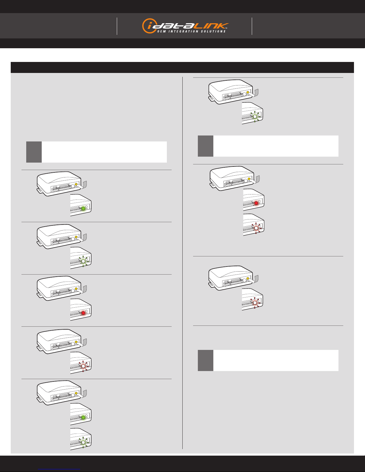
1To access the MENUS:
Press and hold programming
button until LED turns solid
GREEN.
Release programming button.
!To exit the Module Navigation at any time:
Follow step 8.
5To access the SETTINGS:
Press and hold programming
button until LED turns solid
GREEN.
Release programming button.
LED will fl ash GREEN as many
times as the current (or default)
setting number, continuously.
9Module navigation completed.
!To return to the MENUS: exit the Module Navigation and
redo the Module Navigation Procedure.
!Failure to exit the Module Navigation will drain vehicle
battery.
2In the MENUS:
Press the programming button
as many times as the menu
number indicates.
LED will fl ash GREEN an equal
amount of times continuously.
4In the OPTIONS:
Press the programming button
as many times as the option
number indicates.
LED will fl ash RED an equal
amount of times continuously.
3To access the OPTIONS:
Press and hold programming
button until LED turns solid
RED.
Release programming button.
6In the SETTINGS:
Press the programming button
as many times as neccesary to
access your setting.
LED will fl ash GREEN an equal
amount of times continuously.
8MANDATORY:
EXIT MODULE NAVIGATION
Press and hold programming
button for 7 seconds.
LED will fl ash RED rapidly.
Release programming button.
LED will turn OFF.
7To save and return to the
OPTIONS:
Press and hold programming
button until LED turns solid
RED.
Release programming button.
LED will fl ash RED as many
times as the current option
number continuously.
Confi gure every other setting
and proceed to step 8.
Page 10 of 14 DBI-AL(RS)-CH4-EN 20130212
INSTALL GUIDE
Guides Français disponibles au www.idatalink.com
WWW.IDATALINK.COM/SUPPORT Automotive Data Solutions Inc. © 2013
ALL IN ONE
Chrysler/DoDge/Jeep
Doc. No.: ##10835##

XX-XX PAGE X-X
MODULE NAVIGATION CHART
ADS-AL(RS)-CH4 PAGE X-X
MENUS OPTIONS SETTINGS
1
CONFIGURATION
1DISARM/UNLOCK BEFORE
START
1OFF
2ON
2RELOCK AFTER START
1OFF
2ON
3RELOCK AFTER SHUTDOWN
1OFF
2ON
4FORCE UNLOCK ALL ON FIRST
PRESS
1OFF
2ON
5TAKEOVER
1ENABLE
2DISABLE*
6SECURE TAKEOVER DELAY
145 SEC
290 SEC
303 MIN
404 MIN
7FACTORY KEYLESS
RS SEQUENCE
1DISABLE
2N/A
3LOCK + UNLOCK + LOCK
4LOCK + LOCK + LOCK
8MODULE RUN TIME
103 MIN
205 MIN
310 MIN
415 MIN
525 MIN
630 MIN
735 MIN
815 MIN
9WAIT TO START DELAY
102 SEC
205 SEC
308 SEC
410 SEC
515 SEC
620 SEC
725 SEC
830 SEC
10 N/A 1N/A
11 N/A 1N/A
12 N/A 1N/A
2N/A
3N/A
4Technical Support Only
5Technical Support Only
6Technical Support Only
7Technical Support Only
NOTE
I Default settings are listed in bold.
II Make sure the option is covered on the vehicle before
attempting to change the setting.
*Vehicle will shudown when a door is opened.
Page 11 of 14 DBI-AL(RS)-CH4-EN 20130212
INSTALL GUIDE
Guides Français disponibles au www.idatalink.com
WWW.IDATALINK.COM/SUPPORT Automotive Data Solutions Inc. © 2013
ALL IN ONE
Chrysler/DoDge/Jeep
Doc. No.: ##10835##

REMOTE STARTER ERROR CODES
NOTE
I WARNING: The following applies only when the parking lights
are connected and supported by the system.
II After a remote starter failure, the parking lights will fl ash [X]
number times to indicate an error code. See table.
[X] NUMBER OF
PARKING LIGHT
FLASHES
REMOTE STARTER ERROR CODES
3 Foot brake is ON.
4 Hood is open.
5 Engine tach signal is lost.
6 System is in Valet Mode.
7 Vehicle is moving (VSS).
8 Glow plug timeout error.
Page 12 of 14 DBI-AL(RS)-CH4-EN 20130212
INSTALL GUIDE
Guides Français disponibles au www.idatalink.com
WWW.IDATALINK.COM/SUPPORT Automotive Data Solutions Inc. © 2013
ALL IN ONE
Chrysler/DoDge/Jeep
Doc. No.: ##10835##

XX-XX PAGE X-XCLASSIC PAGE 1-1
LED STATUS
DIAGNOSTICS
DURING PROGRAMMING DURING REMOTE START WITH IGNITION OFF
Flashing RED Missing/wrong information from
fi rmware or vehicle Incorrectly programmed Incorrectly programmed or connected
Solid RED Waiting for more vehicle information Incorrectly programmed Not programmed waiting for more
vehicle information
Flashing GREEN Additional steps required to complete
programming
Correctly programmed and
operational
False ground when running status
from remote starter
Solid GREEN then OFF Correctly programmed Reset in progress Reset in progress
OFF No activity or already programmed Invalid ground when running status
from remote starter
At rest and ready for a remote start
sequence
MODULE DIAGNOSTICS
FACTORY RESET PROCEDURE
7Repeat programming procedure.
!Failure to follow procedure may result with a DTC or a
CHECK ENGINE error message.
1DISCONNECT all connectors
from module EXCEPT the black
4-PIN standard or optional data
connector.
6RECONNECT all connectors.
2DISCONNECT black 4-PIN
standard or optional data
connector.
4When LED fl ashes red,
RELEASE programming button.
5LED will turn solid red for 2
seconds.
RESET COMPLETED.
3PRESS AND HOLD programming
button while connecting either
4-PIN standard or optional data
connector.
IDENTIFY VEHICLE YEAR
1Locate the Vehicle Identifi cation
Number (VIN) and identify the
10th character.
2Match the VIN’s 10th character
to its corresponding year.
L > 1990 S > 1995 Y > 2000 5 > 2005 A > 2010
M > 1991 T > 1996 1 > 2001 6 > 2006 B > 2011
N > 1992 V > 1997 2 > 2002 7 > 2007 C > 2012
P > 1993 W > 1998 3 > 2003 8 > 2008 D > 2013
R > 1994 X > 1999 4 > 2004 9 > 2009 E > 2014
4 Y 1 N53 A 5 T A L 8 D 5 R 0 X
Page 13 of 14 DBI-AL(RS)-CH4-EN 20130212
INSTALL GUIDE
Guides Français disponibles au www.idatalink.com
WWW.IDATALINK.COM/SUPPORT Automotive Data Solutions Inc. © 2013
ALL IN ONE
Chrysler/DoDge/Jeep
Doc. No.: ##10835##

TAKE OVER PROCEDURE - TO THE VEHICLE OWNER
2Insert key into ignition.
3Turn key to ON position.
Wait 2 seconds for key
validation.
ON
5Take over procedure completed.
4Press and release BRAKE pedal.
!Failure to follow procedure will result in vehicle engine
shutdown.
NOTE
I All vehicle doors must be closed and locked prior to remote
start sequence.
1Press UNLOCK on after-market
remote.
TAKE OVER PROCEDURE - PUSH TO START - TO THE VEHICLE OWNER
4Take over procedure completed.
3Press and release BRAKE pedal.
!Failure to follow procedure will result in vehicle engine
shutdown.
NOTE
I All vehicle doors must be closed and locked prior to remote
start sequence.
1Press UNLOCK on after-market
remote.
2DO NOT PRESS BRAKE PEDAL
Push start button twice [2x] to
ON position.
Wait 2 seconds for key
validation.
x2
ADS-AL(RF)-CH4 PAGE X-X
Page 14 of 14 DBI-AL(RS)-CH4-EN 20130212
INSTALL GUIDE
Guides Français disponibles au www.idatalink.com
WWW.IDATALINK.COM/SUPPORT Automotive Data Solutions Inc. © 2013
ALL IN ONE
Chrysler/DoDge/Jeep
Doc. No.: ##10835##
This manual suits for next models
1
Table of contents
Other iDataLink Remote Starter manuals

iDataLink
iDataLink ADS-AL-HK2-EN User manual

iDataLink
iDataLink ADS-TB-FM3-EN User manual

iDataLink
iDataLink ADS-ALCA User manual

iDataLink
iDataLink ADS-TB-HA6-EN User manual

iDataLink
iDataLink BLADE Series User manual

iDataLink
iDataLink BLADE Series User manual

iDataLink
iDataLink ADS-AL(DL)-MI2-EN User manual

iDataLink
iDataLink BLADE-TB-FM3-EN User manual

iDataLink
iDataLink iDataStart VWX000A User manual

iDataLink
iDataLink BLADE Series User manual