Ideal Air BELIMO LM24A-SR User manual

idealairgroup.com.au
LM24A-SR
damper
actuator
LM24A-SR

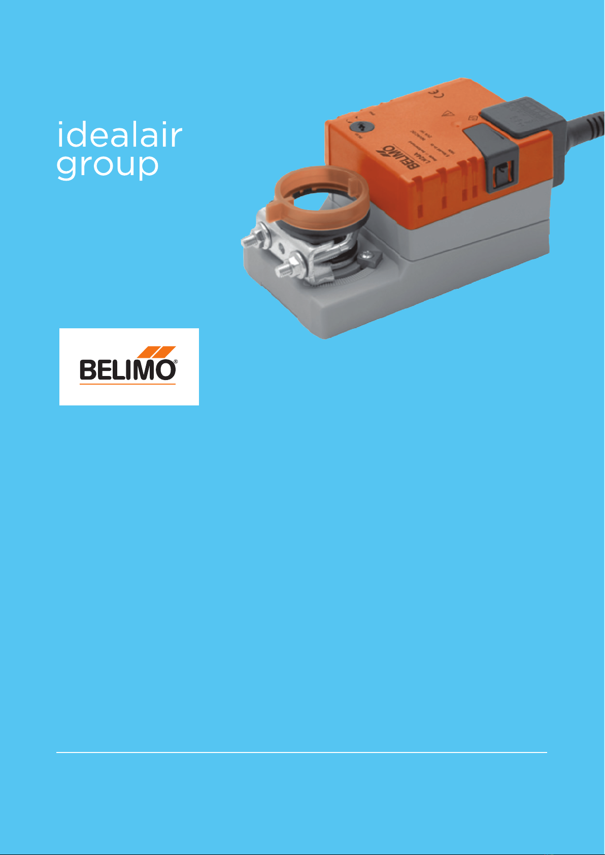
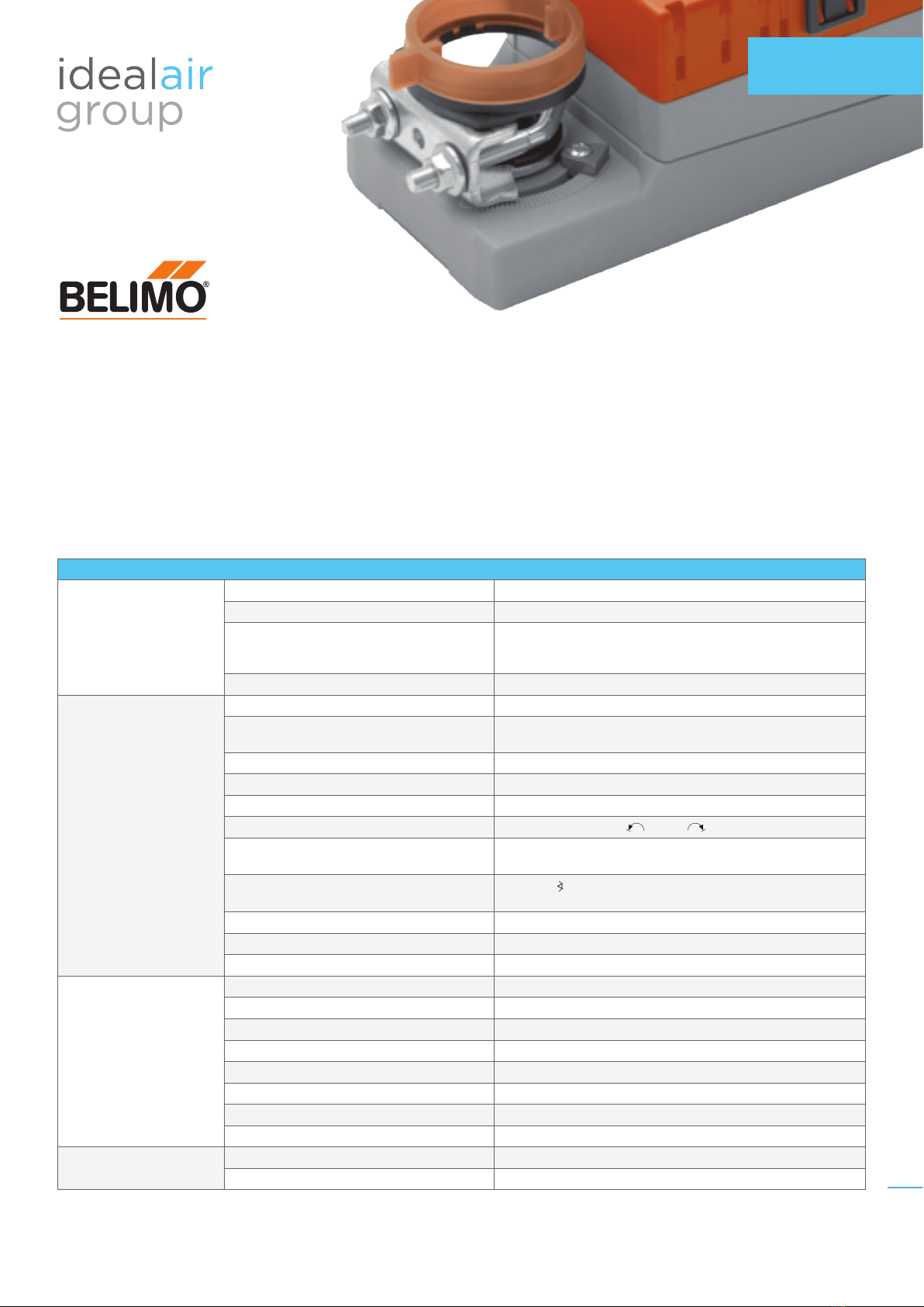
LM24A-SR DAMPER ACTUATOR
Overview
Damper actuator for operating air control dampers in ventilation and air-conditioning systems for building
services installations for air dampers up to approx. 1m2. Torque 5 Nm. Nominal voltage AC/DC 24V.
Control: modulating DC 0 ... 10 V, position feedback DC 2 ... 10 V.
Technical Data
Technical Data
Electrical Data
Nominal Voltage AC 24 V, 50/60 Hz / DC 24 V
Nominal Voltage Range AC/DC 19.2 ... 28.8 V
Power Consumption - In Operation
- At Rest
- For Wire Sizing
1 W @ nominal torque
0.4 W
2 VA
Connection Cable 1m, 4 x 0.75mm
2
Functional Data
Torque (Nominal Torque) Min. 5 Nm @ nominal voltage
Control - Control Signal Y
- Working Range
DC 0 ... 10 V, typical input impedance 100 kΩ
DC 2 ... 10 V
Position Feedback (Measuring Voltage) DC 2 ... 10 V, max. 1 mA
Position Accuracy ±5%
Direction of Rotation Reversible with switch 0 / 1
Direction of Rotation at Y = 0 V At switch position 0 resp. 1
Manual Override Gearing latch disengaged with pushbutton,
self-resetting
Angle of Rotation Max. 95° , limited on both sides by means of adjustable,
mechanical end stops
Running Time 150s
Sound Power Level Max. 35 dB (A)
Position Indication Mechanical, pluggable
Safety
Protection Class III Safety extra-low voltage
Degree of Protection IP54 in any mounting position
EMC CE according to 89/336/EEC
Mode of Operation Type 1 (to EN 60730-1)
Ambient Temperature Range –30 ... +50°C
Non-Operating Temperature –40 ... +80°C
Ambient Humidity Range 95% r.H., non-condensating (EN 60730-1)
Maintenance Maintenance-free
Dimensions / Weight Dimensions See Product Specications on page 3
Weight Approx. 500g
2
TECHNICAL
DATA SHEET
info@idealairgroup.com.au idealairgroup.com.au
122017

Safety Notes
• The actuator is not allowed to be used outside the specied eld of application, especially in aircraft
or any other form of air transport.
• Assembly must be carried out by trained personnel. Any legal regulations or regulations issued
by authorities must be observed during assembly.
•
The device may only be opened at the manufacturer‘s site. It does not contain any parts that can be replaced
or repaired by the user.
• The cable must not be removed from the device.
• When calculating the required torque, the specications supplied by the damper manufacturers
(cross section, design, installation site), and the air ow conditions must be observed.
• The device contains electrical and electronic components and is not allowed to be disposed
of as household refuse. All locally valid regulations and requirements must be observed.
Product Specications
Mode of Operation
The actuator is controlled by means of a standard control signal DC 0 ... 10 V. It opens to the
position dictated by this signal. The measuring voltage U allows the damper position (0 ... 100%)
to be electrically indicated and serves as a follow-up control signal for other actuators.
Simple Direct Mounting Simple direct mounting on the damper spindle with a universal spindle clamp, supplied with
an anti-rotation strap to prevent the actuator from rotating.
Manual Override Manual operation is possible with the self-resetting pushbutton (the gearing latch remains
disengaged as long as the pushbutton is pressed).
Adjustable Angle of Rotation Adjustable angle of rotation with mechanical end stops.
High Functional Reliability The actuator is overload-proof, requires no limit switches and automatically stops when the
end stop is reached.
116
47
61
22 94 41
66
Damper Spindle
Length min. 37
6 ... 20
33
info@idealairgroup.com.au idealairgroup.com.au
122017

Electrical Installation
Accessories
OPEN-CLOSE CONTROL
WIRING DIAGRAM
Y
U
1 32 5
DC 0…10 V
DC 2…10 V
– +
T
~
Note -
• Connect via safety
isolation transformer.
• Other actuators
can be connected
in parallel. Please note
theperformance data.
Description Data sheet
Electrical Accessories
Auxiliary Switch S..A.. T2 - S..A..
Feedback Potentiometer P..A.. T2 - P..A..
Range Controller SBG24 T2 - SBG24
Positioner SG..24 T2 - SG..24
Digital Position Indication ZAD24 T2 - ZAD24
Mechanical Accessories Shaft Extension AV6-20 T2 - Z-LM..A..
Technical Drawings
6...20
≥6≤20
≥37
DRAWING 1
2
1
DRAWING 2
1
2
1
≈1mm
DRAWING 3
6Nm
10
8
2
1
1
≈
1mm
DRAWING 4
65°
1
2
DRAWING 5
1
2
3
M
M
DRAWING 6
44
info@idealairgroup.com.au idealairgroup.com.au
122017

AC 24 V / DC 24 V
DC 48...110 V
(LM72A..)
123
–+
T
~
+
~
12
32
3
0...100%
S1 S2 S3
–+
T
~
+
~
1 S1 S2 S3
1
0
–+
T
~
+
~
LM24A.. LMC24A..
LM72A.. TMC24A..
LM24A-S.. TMC24A-S..
LM72A-S..
LM24AP5..
AC 24 V / DC 24 V
132 5
– +
T
~
+
~
Y
DC 0...10 V
U
DC 2...10 V
132 5
–
T
Y
DC 0...10 V
U
MP
LM24A-SR.. LMC24A-SR..
LM24A-MF.. TMC24A-SR..
LM24A-MP..
12
– +
T
~
VR..
LM24A-V
LM24A-V / VR..
AC 24 V / DC 24 V
(LM24A-V / VR..)
1
0
NL
123
1
0
1
0
–+
T
~
1 2 3
0
N L
– +
T
~
AC
100...240 V N LL
123 3
N LL
12
0...100%
S1 S2 S3
S1 S2 S3
1
0
S1 S2 S3
1
0
LM230A.. LMC230A..
TMC230A..
LM230A-S.. TMC230A-S..
DC 48...110 V
(LM72A-SR..)
Y
U
1 32 5
T
1 2
DC 0...10 V
DC 2...10 V
– +
SG..24
LM72A-SR..
AC
100...240 V Y
1 32 5
T
N L
1 2
DC 0...10 V
DC 2...10 V
SG..24
LM230ASR.. TMC230ASR..
U
55
info@idealairgroup.com.au idealairgroup.com.au
122017
Table of contents