IDEAL EXRKIT08 User manual

NOTICE
NOTICE
NOTICE
Exalt WHB & FSB
Natural Gas to Propane Conversion Instructions
Kit Part Number
•
EXRKIT08 (Heat Only 110)
•
EXRKIT10 (Heat Only/Combi 155)
•
EXRKIT12 (Heat Only/Combi 199)
Kit Includes
•
Rating Label
•
Conversion Label
•
(1) Propane Gas Venturi
•
Acoustic Foam (required for 110 and 155 models ONLY)
Recommended Tools
•
Adjustable Wrench / 10 mm Socket & Ratchet
•
Phillips Head Screwdriver
•
Flat Head Screwdriver
•
Calibrated Combustion Analyzer
Indicates a potentially hazardous situation
which, if ignored, can result in serious injury or
substantial property damage.
Indicates special instructions on installation, operation
or maintenance, which are important to equipment
but not related to personal injury hazards.
When converting the appliance from Natural Gas to Propane ensure that the conversion is completed before fully installing
the air inlet piping.
For your safety, turn off electrical power supply
at service panel and allow unit to cool before pro-
ceeding to avoid possible electrical shock and
scald hazard. Failure to do so can cause severe
personal injury or death.
Upon completion of the conversion from Natural to Pro-
pane, affix the new rating label included in the kit to the
unit adjacent to the existing rating label. DO NOT affix
the new label over the existing rating label. Add propane
conversion labelling to the gas valve.
Failure to follow instructions below can result in
severe personal injury or damage if ignored.
•
Instructions are for a qualified installer/
service technician only.
•
Read all instructions before proceeding.
•
Follow instructions in proper order.
These instructions cover NG to LP conversion for Exalt
boilers only. Each kit is supplied with one venturi.
227798 A02
Revision Date: 10/2021
2019-30 Exalt WHB & FSB Natural
Gas to Propane Conversion
Instructions
! WARNING
! WARNING
NOTICE
!
WARNING
EXALT NATURAL GAS TO PROPANE CONVERSION INSTRUCTIONS
NOTICE
1.
Preliminary Instructions:
1.
Verify that the venturi replacement kit is correct for
the model of boiler. See page 1.
2.
Turn off electrical power supply to the boiler.
3.
Close the manual gas shut off valve to the unit.
4.
Remove the front panel of the Exalt.
For the floor standing model:
Remove the two securing screws on top of the
control pod. Rotate the pod upwards. Lift the front
panel to disengage the keyhole slots and remove
the panel.
Re-fit in the reverse order.
For the wall hung model
Remove the securing screw holding the bottom of
the front panel to the chassis. Pull the bottom of
the front panel out and lift to disengage from the
top mounting points.
Re-fit in the reverse order.
5.
Using a voltmeter ensure there is no electrical
power to the boiler by checking for power on the
boiler’s high voltage terminals L and N.
The Exalt boiler has a length of acoustic foam already
installed in the air inlet adaptor. DO NOT remove this
3.
Insert the length of acoustic foam (supplied),
into the 7" pipe length.
4.
Use either a straight coupling or elbow to
continue the air inlet installation. Refer to
the Vent Supplement for full details on the
installation of air and vent pipes.
ELECTRICAL SHOCK HAZARD
Ensure power to the boiler has been disconnected
prior to servicing the unit.
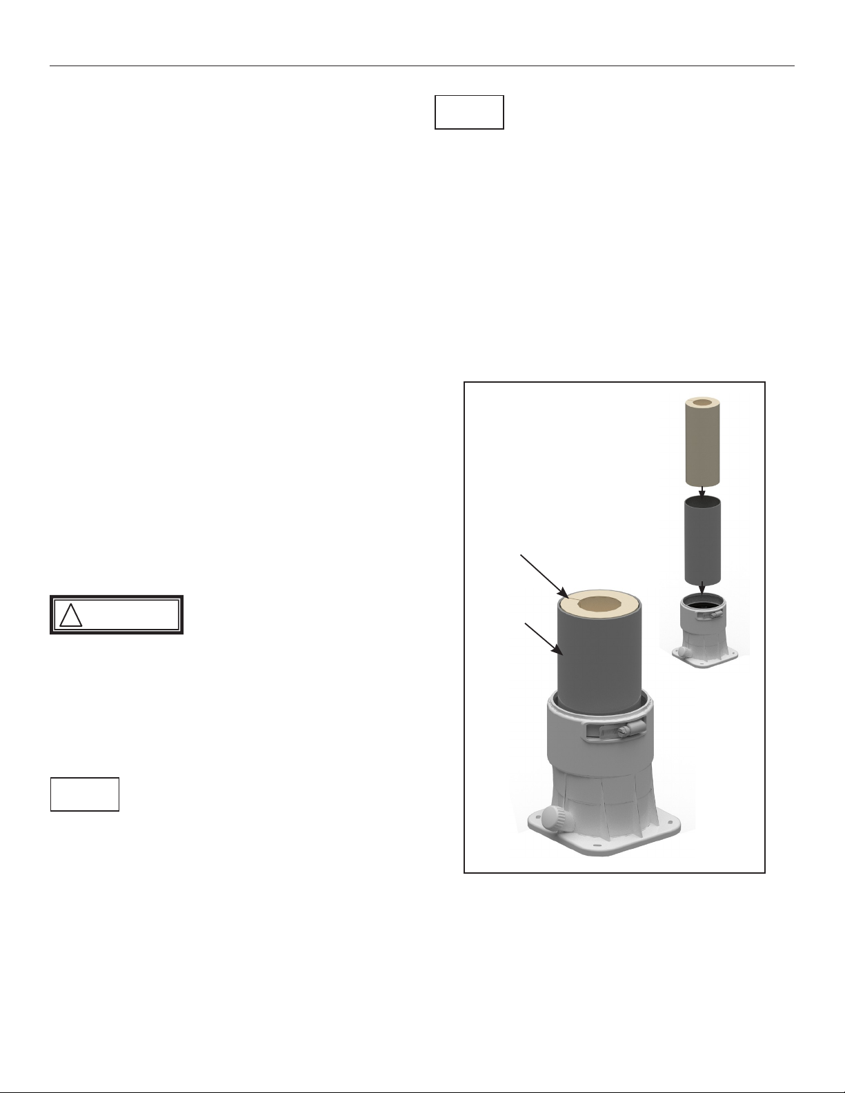
2.
Install the Acoustic Foam
The acoustic foam is only applicable to the 110 and 155
models. The Exalt 199 models do NOT use the additional
acoustic foam.
1.
Cut a 7" length of 3" diameter air inlet piping.
2.
Insert the 7" pipe into the air inlet adaptor.
Fig. 1: Installing the Acoustic Foam (applicable to 110
and 155 models ONLY)
NOTICE
!
WARNING
Acoustic
Foam
Acoustic
Foam
7" Air
Inlet
Pipe
7" Air Inlet
Pipe
Boiler
Air Inlet
EXALT NATURAL GAS TO PROPANE CONVERSION INSTRUCTIONS
NOTICE
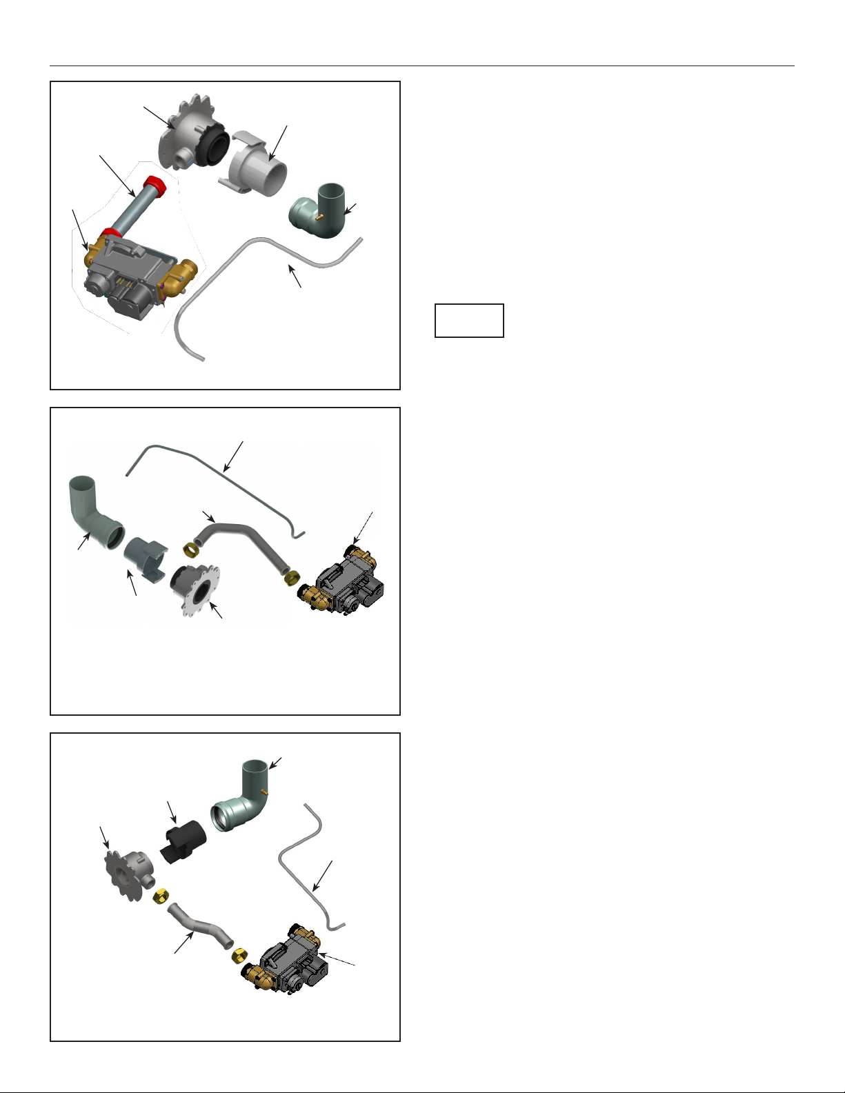
Air Inlet
Venturi
Interface
Venturi
Air Reference
Hose
Pipe to
Venturi
Gas Valve
Fig. 4: Exalt 199 Gas Train
3.
Removal of Natural Gas Venturi
1.
Remove the silicone tube from the air inlet elbow,
then remove the air inlet elbow.
2.
Rotate the venturi interface approximately 60°
clockwise to release the clamping mechanism and
remove the venturi interface.
3.
Remove the gas valve to venturi pipe by loosening
the nuts at both ends of the pipe with an adjustable
wrench.
There are gaskets at both ends of the gas valve to venturi
pipe. These gaskets must be reinstalled along with the pipe.
Use care not to damage the gaskets.
4.
Using a 10 mm socket and ratchet, remove the
three (3) bolts securing the venturi to the fan
assembly and remove the natural gas venturi from
the unit, making sure not to damage the blower
O-ring gasket.
4.
Install the propane venturi
1.
Verify the following when aligning the propane
venturi:
1.
The UP arrow on the plastic housing is pointing
upward.
2.
The threaded connection for the gas piping is in
the correct orientation for re-fitting the gas pipe.
Venturi
Venturi Interface
Pipe to Venturi
Gas Valve
Air Inlet
Air Reference Hose
Fig. 2: Exalt 110 Gas Train
Air Reference Hose
Pipe to Venturi
Gas Valve
Air Inlet
Venturi
Interface
Venturi
Fig. 3: Exalt 155 Gas Train

EXALT NATURAL GAS TO PROPANE CONVERSION INSTRUCTIONS
!
WARNING
NOTICE
!
WARNING
Failure to retain the O-ring gasket between the venturi
and the blower will cause an improper seal resulting
in a potential risk of a gas leak. A gas leak can result in
substantial property damage, serious injury, or death.
Ensure the correct venturi for the model is installed.
Natural gas venturis have a white identification label
and LP venturis have a black label. Failure to comply
will affect input rate and combustion of the boiler
which can result in substantial property damage,
serious injury, or death.
Do not use adhesive on any gaskets or O-rings during the
reassembly process.
2.
Using a 10 mm socket and ratchet, reinstall the
three (3) bolts securing the venturi to the fan
assembly
3.
Reassemble the gas valve to venturi pipe to the
gas valve and venturi taking care to ensure that the
gaskets are seated properly before tightening the
nut.
4.
Install the venturi interface on the venturi and
rotate counterclockwise until locked into place.
5.
Install the air inlet elbow then attach the silicone
tube.
Failure to properly install the air inlet elbow and attach
the silicone tube can affect combustion of the boiler
which can result in substantial property damage,
serious injury, or death.
6.
Open the manual gas shut off valve to the unit.
Before placing the boiler back into operation, test
all gas connections for leaks and repair if leaks are
found.
Do not check for gas leaks with an open flame. Use a
bubble test. Failure to test for gas leaks can result in
substantial property damage, serious injury, or death.
7.
Attach the propane conversion label to the gas
valve and the propane conversion rating label next
to the existing rating label
8.
Enter the propane (LP) appliance code from the
propane rating label supplied in the conversion kit:
1.
Press and hold the UP and DOWN buttons
together see Fig. 5.
Fig. 5:
CTRLMax Navigation Control
2.
Enter the installer access code “054” by using
the LEFT and RIGHT buttons to select a digit and
the UP and DOWN buttons to change the digit.
Press the center button to enter the access code.
3.
With the CH/DHW Settings icon highlighted,
press the center button.
4.
Press the DOWN button to highlight the Boiler
Settings icon then press the center button.
5.
Scroll down to highlight Appliance Setting then
press the center button.
6.
Enter the propane (LP) appliance code from
the rating label by using the LEFT and RIGHT
buttons to select a character and the UP and
DOWN buttons to change the character. Press
the center button to enter the appliance code.
!
WARNING
!
WARNING

EXALT NATURAL GAS TO PROPANE CONVERSION INSTRUCTIONS
NOTICE
! WARNING
! WARNING
NOTICE
5.
Combustion Test and Adjustments
The installer MUST perform a complete combustion check to
ensure the following combustion levels are met at high and
low input firing rates and the burner is operating at optimum
conditions.
The combustion testing and adjustments must be
performed by a qualified installer, service agency or
the gas supplier. All combustion measurements must
be performed with calibrated equipment to ensure
proper readings and accuracy. Refer to Table 1 to
check the combustion is within the acceptable range.
Failure to perform a complete combustion test at both
high and low input rates may result in incomplete
combustion and the production of carbon monoxide,
which can cause severe personal injury, death or
substantial property damage.
1.
Touch simultaneously on the up and down soft
keys for 3 seconds to access the functions for the
installer. See Fig. 5.
2.
Enter the installer access code “054” by using the
LEFT and RIGHT buttons to select a digit and the UP
and DOWN buttons to change the digit. Press the
CENTER button to enter the access code.
3.
Press the RIGHT button to highlight the Manual
Operation icon then press the CENTER button.
4.
Press the CENTER button while the FAN icon is
highlighted to manually fire the burner and power
the CH circulator. See Fig. 6.
An adequate CH load must be present to dissipate the heat
generated during the combustion test. If an adequate CH
load is not available, an indirect water heater can be used to
dissipate the heat by creating a DHW call which will enable the
DHW circulator.
5.
Press the RIGHT button to adjust the firing rate to
100% (high fire). Hold down the RIGHT button to
rapidly increase the firing rate.
6.
If the combustion levels during high fire are outside
the recommended combustion settings (see Table 1),
adjust the THROTTLE SCREW (see Fig. 7) using a flat-
blade screwdriver as follows:
Counter-clockwise adjustment of the THROTTLE
SCREW at High Fire (100% firing rate):
O
2
decreases and CO
2
increases
Clockwise adjustment of the THROTTLE SCREW at
High Fire (100% firing rate):
O
2
increases and CO
2
decreases
7.
Once the combustion level is set at high fire, manually
place the boiler into low fire mode by pressing the
LEFT button to adjust firing rate down to 1% (low
fire).
8.
If the combustion level (O
2
or CO
2
) during low fire is
Fig. 6:
CTRLMax Manual Operation
outside the recommended combustion settings in
Table 1 contact Ideal USA Technical Support.
9.
Press the CENTER button while the fan icon is
highlighted to shutdown the burner.
10.
Press the LEFT or RIGHT button to highlight the home
screen icon to exit the service mode.
11.
Replace the front panel and put the boiler back into
operation.
Manual Operation
Released
CH1
DHW
CH2
Off
Off
Off
FAN

EXALT NATURAL GAS TO PROPANE CONVERSION INSTRUCTIONS
Table 1: Combustion Settings
Propane 110, 155
Propane 199
High Fire
CO
2
Range
10.0 - 11.0%
CO
2
Target
10.8%
O
2
Range
5.7 - 4.2%
O
2
Target
4.5%
CO Max
<200 ppm @ 10.8% CO
2
Low Fire
CO
2
Range
10.0 - 11.0%
CO
2
Target
10.8% 10.4%
Target values are equivalent to High Fire values, ensure
CO₂ values measured are less than or equal to High Fire
CO₂ measurements
O
2
Range
5.7 - 4.2%
O
2
Target
4.5% 5.1%
Target values are equivalent to High Fire values, ensure
O₂ values measured are higher than or equal to High Fire
O₂ measurements
CO Max
10 ppm
Throttle Screw
Fig. 7: Throttle Screw Location
This manual suits for next models
2
Table of contents
Other IDEAL Boiler Supplies manuals


