7
4-1-1-2 Not available at this
level This item will not be displayed the next available menu item being displayed
will be 4-1-1-3
4-1-1-3 Rated Output Displays the maximum operating capacity of the unit (which may be less
than the unit capacity up to 50% by fitting an alternative value UCP1)
4-1-1-4 Unit Type Displays the unit type i.e. “LE” or “LEP”
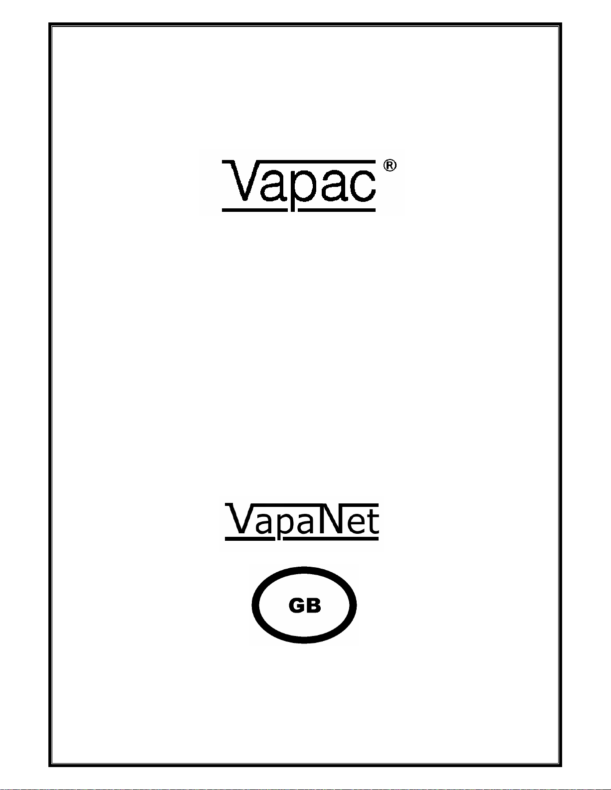
4-1-1-5 SW Version Displays the software version fitted in the control PCB
4-1-1-6 Nominal Voltage Displays the nominal supply voltage – as set during the initial unit “setup “.
4-1-1-7 Num Electrodes Displays the number of electrodes fitted to each cylinder.
4-1-1-8 Num of turns Displays the number of times the electrode cable passes through the
current sensing transformer or “toroid “
4-1-1-9 Steam Units Displays whether the steam output is measured in kg/h or lbs/h
4-1-1-10 Control Input Displays the selected control signal – set during initial unit “setup”
4-1-1-11 Slaves Attached Displays the number of slave units attached to the network
4-1-1-12 Num Cylinders Displays the total number of cylinders attached to the system or network
4-1-1-13 VOS Algorithm Displays the selected algorithm which is used by Vapac Operating System
either “VOS 4” or “VOS 6” the standard setting is “VOS 6”
4-1-1-14 Water Economy Displays whether water economy is “enabled” or “disabled”
4-1-2-1 Cyl Capacity Displays the maximum amount of steam that the cylinder is designed to
produce
4-1-2-2 Cylinder Type Displays whether the cylinder is “LE” or “LEP”. i.e. if the cylinder power is
modulated by SSR’s (close control) or not (comfort control)
4-1-2-3 Period drain int Displays the time interval between periodic drains – “0” indicates that
periodic drains have not been selected. Periodic drains can be set to
completely drain the cylinder at timed intervals which can assist unit
operation under certain conditions
4-1-2-4 Drain options Displays whether the unit is set to stop or resume automatic operation once
the periodic drain cycle is complete
4-1-2-5 Period flush int Displays the time interval between periodic flushes – “0” again indicates
that periodic flushes have not been selected. Periodic flushes can be set to
completely drain the cylinder then re-fill with fresh water and finally drain the
cylinder again to flush the cylinder at timed intervals. This can again assist
unit operation under certain conditions
4-1-2-6 Flush options Displays whether the unit is set to stop or resume automatic operation once
the periodic flush cycle is complete
4-1-3-1 to 4-1-3-6 The cylinder information options are repeated for cylinder 2 (if fitted)
4-2 to 4-9-3-6 The unit and cylinder information options are repeated for slave units 1 to 9
if fitted to the system. NB the maximum number of cylinders on any system
is 10