Miura BP-201 User manual

Document Control #: 001157
June 3, 2016
INSTALLATION
MANUAL
Boiler Room
Operation Panel
BP-201
This document was formulated in
Japan. Comply with the regulations
and standards of the country of
usage.
The specifications of products and
components may vary with country of
usage and site situation.
INFORMATION IN THIS MANUAL
MAY BE CHANGED WITHOUT
NOTICE

Document Control #: 001157
June 3, 2016
Introduction
This Installation Manual explains the transport and installation of the boiler system operation
panel BP-201.
Carefully read this Installation Manual and understand the contents before installing the boiler
system operation panel BP-201. Particularly important points are denoted as DANGER,
WARNING, CAUTION, and NOTE in descending order of severity.
Indicates an imminently dangerous situation which leads to
serious injury or death to the user, if the product is mishandled.
Indicates a situation which might cause serious injury or death
to the user, if the product is mishandled.
Indicates a situation which might cause minor injury to the user
or the occurrence of physical damage only, if the product is
mishandled.
Describes the precautions to prevent failures of the product,
points to perform effective operation, and useful information to
know.

Table of Contents
Introduction.................................................................................................................. i
1. Precautions Regarding Installation .................................................................... 1
2. Overall Dimensions .............................................................................................. 2
2.1 BP-201STA ........................................................................................................................... 2
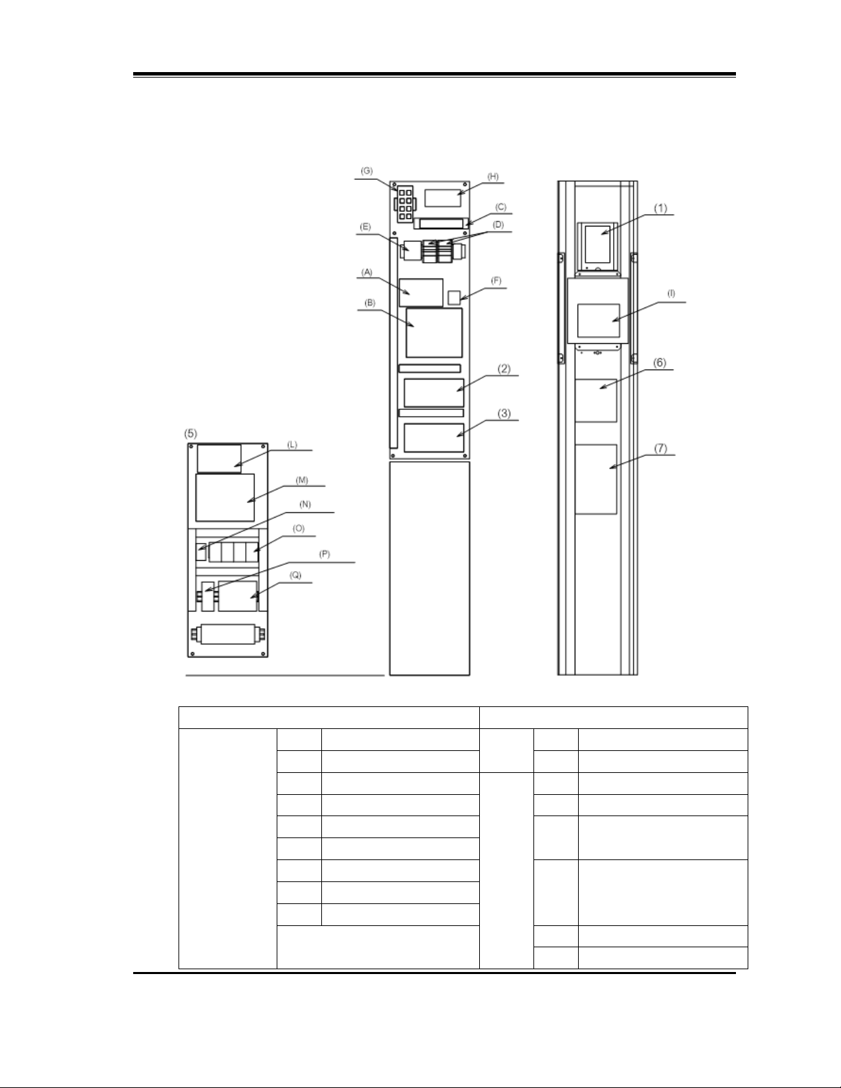
2.2 Layout and Names of Internal Parts ..................................................................................... 3
2.3 Options and Equipment Configuration.................................................................................. 4
3. Accessories .......................................................................................................... 5
3.1 Steam Pressure Sensor........................................................................................................ 5
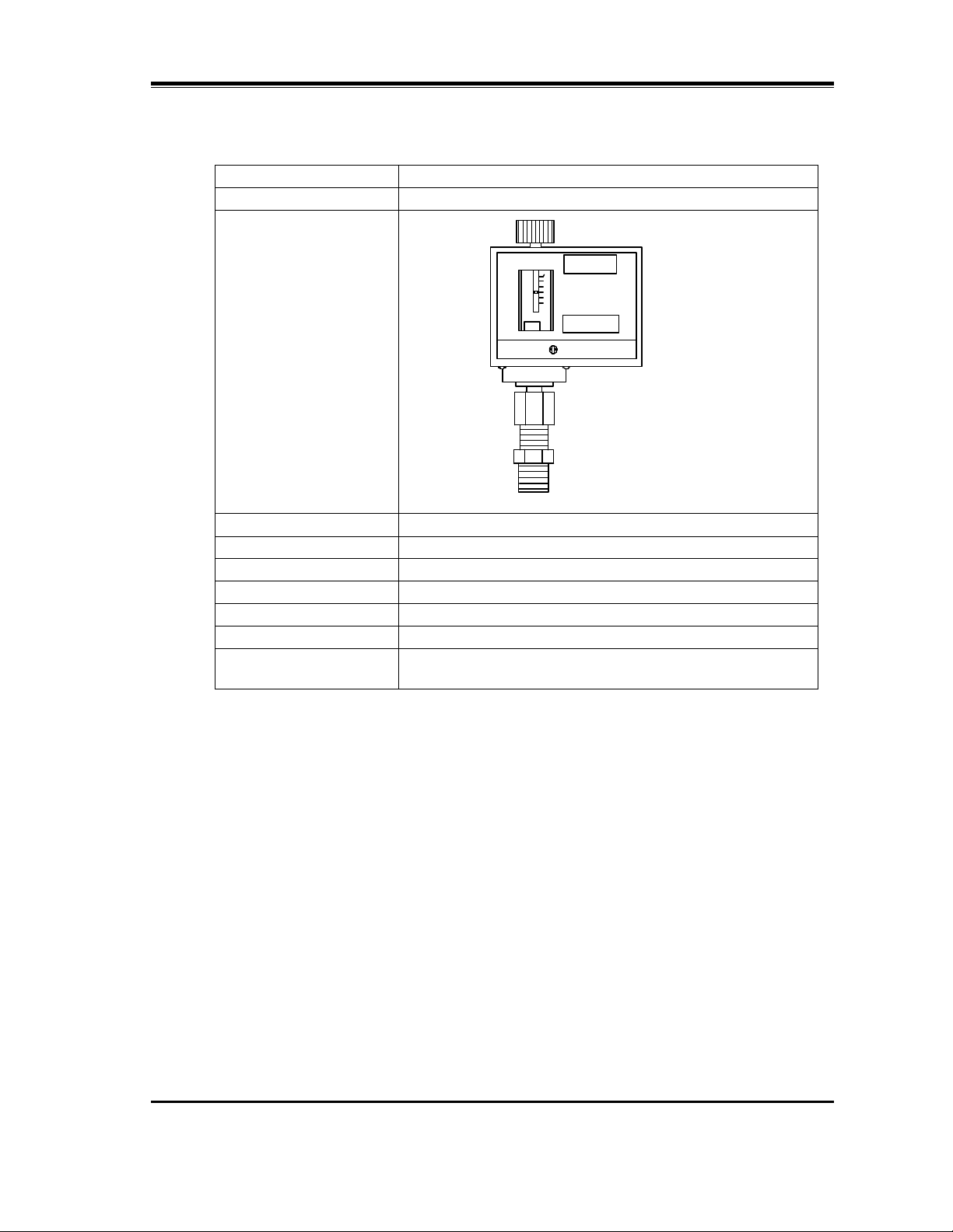
3.2 Steam Pressure Switch ........................................................................................................ 6
4. Carrying................................................................................................................. 7
5. Installation............................................................................................................. 7
5.1 Precautions when Installing the Main Unit ...........................................................................7
5.2 BP-201STA Installation ......................................................................................................... 9
5.3 Precautions when Installing the Steam Pressure Sensor and Steam Pressure Switch .... 10
6. Wiring Work .........................................................................................................11
6.1 Precautions ......................................................................................................................... 11
6.2 Wiring .................................................................................................................................. 12
6.3 Terminal Sequence of the Control Board ...........................................................................15
6.4 Wires and Terminal Processing .......................................................................................... 18
6.5 Steam Pressure Sensor Wiring .......................................................................................... 19
6.6 Steam Pressure Switch Wiring ........................................................................................... 20
6.7 M-NET3 Cable Wiring......................................................................................................... 21
6.8 Earthquake Detector Wiring................................................................................................ 22
6.9 Flowmeter Wiring................................................................................................................ 23
6.10 Wiring the Dry Contact Inputs and Dry Contact Outputs.................................................... 23
6.11 Telephone Line Wiring ........................................................................................................ 24
6.12 Wiring the Water Treatment Control Unit for Boiler WP2 ................................................... 24
6.13 Wiring the DS-NET Communication Unit ML3 ................................................................... 24
7. Attaching the MI Number Label......................................................................... 25

Document Control #: 001157
1
All copies of the document are uncontrolled when printed
1. Precautions Regarding Installation
When installing the equipment and performing the instrumentation work, take due care of the
following precautions.
1. When performing the grounding work, connect the ground wire to the ground terminal
inside the panel. Use wire with a diameter equal to or larger than the power supply wire
(AWG-12).
2. Do not install an overcurrent circuit breaker in the grounding wire.
3. Install an independent ground fault circuit breaker (with overcurrent protection) within 10 ft
(3 m) of the node point in the low-voltage interior wiring.
Power circuit breaker capacity
[A]
Rated sensitivity current
[mA]
BP-201STA 15 30
4. Install a ground fault circuit breaker (with overcurrent protection) for each phase (L phase
and N phase).
5. Use a power supply wire with insulation resistance of 0.1 MΩor higher.
6. Use AWG-12 wire or larger diameter for the power line. Protect the wire in a conduit.
7. Protect the steam pressure sensor and steam pressure switch wires in a conduit.
8. Ensure that the total length of each wire for the steam pressure sensor and steam
pressure switch is within 165 ft (50 m).
9. Limit the wire length between the hub and equipment to 330 ft (100 m) or less.

Document Control #: 001157
2
All copies of the document are uncontrolled when printed
2. Overall Dimensions
2.1 BP-201STA
Touch
panel

Document Control #: 001157
3
All copies of the document are uncontrolled when printed
2.2 Layout and Names of Internal Parts
Main parts Optional parts
BP-201STA (A) CPU board (J)
(B) I/O board (K)
(C) Switching power supply WP2 (L) CPU board
(D) Circuit protector (M) I/O board
(E) Terminal block (N) Molded case circuit
breaker
(F) Battery
(G) Hub (O) Ground faoult circuit
breaker (with overcurrent
protection)
(H) Switching power supply
(I) Touch panel
(P) Switching power supply
(Q) Floatless switch

Document Control #: 001157
4
All copies of the document are uncontrolled when printed
2.3 Options and Equipment Configuration
Option Equipment Installed
position Remarks
Telephone modem
specification Telephone modem (1)
Expansion board × 1 Expansion board 1 (2)
Expansion board × 2 Expansion board 1
Expansion board 2 (2) (3)
(4)
Water treatment control
unit for boiler WP2, S
type/F type
WP2 unit (5)
Note 1: The configuration in the
unit differs according to the
options.
Display module (6) The display module is installed
in both the S type and F type.
WP2 chemical feed
option for 3 or more
chemical feed systems Expansion module (7)
The expansion module is not
installed in both the S type and
F type with 1 or 2 chemical feed
systems.

Document Control #: 001157
5
All copies of the document are uncontrolled when printed
3. Accessories
The accessories in the table below are provided with the product. Check the details on the
package contents list. Ensure that all accessories are present and undamaged. If a part is
defective or you have any other concern, contact your dealer or MIURA sales office.
No. Part name Quantity
Remarks
1 Steam pressure sensor 1
2 Steam pressure switch 1
3 A set of mounting fittings 1 Used to fix the main
unit.
4 A set of number label 1
5 Operation Manual 1
6 Package contents list 1 Specifies details of
accessories.
3.1 Steam Pressure Sensor
Specification For 2 MPa
Model FP201-D31-L20A*B/VT-MUR
Overall view
Range 0 – 290 PSIG (0–2 MPa)
Manufacturer Yokogawa Electric Corporation
Output 4–20 mA, DC, 2-wire type
Accuracy ±0.35%F.S.
Operating
temperature 14°F – 176°F
Protection class IP66
Connector R1/4
Material Diaphragm: HASTELLOY C
Connector: SUS316
19.7 [in] (500 [mm])
Butt terminal
Shielded cable
(provided)
R1/4

Document Control #: 001157
6
All copies of the document are uncontrolled when printed
3.2 Steam Pressure Switch
Specification For 2 MPa
Model ANS-C130NMQ
Overall view
Regulated pressure 73 – 435 PSIG
Manufacturer Saginomiya Seisakusho, Inc.
Output Dry contact
Operating temperature 32°F – 158°F (except pressure-receiving parts)
Protection class IP20
Connector R3/8
Material Bellows: SS316L
Joint: SS304

Document Control #: 001157
7
All copies of the document are uncontrolled when printed
4. Carrying
• See the overall view for the dimensions.
* The BP-201STA is packaged in bubble wrap.
• Take care not to impart shocks during carrying the BP-201.
5. Installation
5.1 Precautions when Installing the Main Unit
• Install in a location within the equipment operating environment range (temperature and
humidity).
• Avoid the following locations, which may cause equipment failure.
1) Locations subject to direct sunlight or near equipment that generates heat
2) Hot locations or locations with large temperature fluctuations
3) Locations with high levels of moisture or dust
4) Locations subject to shocks or vibrations
5) Locations in a chemical atmosphere, or locations that may contact chemicals or water
6) Locations near power lines or near equipment that generates strong magnetic fields
7) Locations subject to severe supply voltage fluctuations
CAUTION
Wear protective equipment when carrying the BP-201.
BP-201STA: Up to approx. 132 LB (60 kg) (depending on options)
CAUTION
Observe the following precautions about installation and ensure that
the BP-201 is installed in an appropriate location. Installation in an
inappropriate location may result in equipment failure.

Document Control #: 001157
8
All copies of the document are uncontrolled when printed
• Firmly fix the BP-201 in a location that is free of vibrations.
• Install in a location free of water and condensation.
• During installation, do not touch any of the internal circuit boards. Do not allow dust or
metal fragments to enter inside the BP-201 main unit.
• The maximum wire length between the BP-201 and the steam pressure sensor or steam
pressure switch must not exceed 165 ft. Install the BP-201 in a location where the wires
can reach.
• Ensure adequate space to open the door for adjustment or maintenance work.
• The BP-201 is designed for indoor installation. When installing it outdoors, take
appropriate measures to protect against water, dust, and freezing, and select a location
that is not subject to direct sunlight.
CAUTION
Do not directly weld the box onto a column or wall. The BP-201
contains electrical equipment that may be damaged by the effects of
arc welding.
CAUTION
The holes in the top of the main unit are covered by seals. Remove
the seals only from the wiring hole that is used. Leaving wiring holes
open allows condensation to flow down the wires and into the
equipment.

Document Control #: 001157
9
All copies of the document are uncontrolled when printed
5.2 BP-201STA Installation
Note 1: Fix the 4 corners using either aor b.
Note 2: The BP-201 can be installed also on the right side of the boiler, using the same
method.
Hexagon bolt (with spring washer and plain washer) M12
×
30
Hexagon nut M10
Plain washer M10
H
exagon
bolt M10
×
50
(full threaded)
Plain washer M10
Hexagon nut M10
Plain washer M10
H
exagon
bolt M12
×
2
0
Plain washer M12
Spring washer M12
Hexagon bolt M10
×
50
(full threaded)
Plain washer M12
Fixing jig
Boiler fixing jig
H
exagon
bolt M12
×
2
0
Plain washer M12
Spring
washer M12
Anchor mounting plate
Plain washer M12
Spring washer M12
Hexagon nut M12
Note 1

Document Control #: 001157
10
All copies of the document are uncontrolled when printed
5.3 Precautions when Installing the Steam Pressure Sensor and
Steam Pressure Switch
• Install the steam pressure sensor and steam pressure switch to the steam header
collecting the steam from each boiler.
• Connect the steam pressure sensor and steam pressure switch at a location remote from
the steam outlet piping.
• Install the steam pressure sensor and steam pressure switch in vertical pipes.
• Place in a location free of water vapor and condensation.
• Connect the wiring such that water cannot flow along pipes or wires into the steam
pressure sensor and steam pressure switch.
• Use a syphon tube to adequately cool the piping to the steam pressure sensor and
steam pressure switch. The pressure-receiving parts should not reach 176°F (80°C).
• Do not allow wires to contact hot parts such as the steam header.
Figure 5-1: Example of steam pressure sensor and steam pressure switch installation
CAUTION
Do not install a pressure-reducing valve, accumulator, or other device that
changes pressure between the boiler and the steam header on which the
steam pressure sensor and steam pressure switch are installed.
If a device such as a pressure-reducing valve or accumulator is used,
install the steam pressure sensor and steam pressure switch between the
boiler and the device.
Pressure gauge
Steam pressure sensor
R1/4
Steam
pressure switch
R3/8
Syphon tube
From Steam header
Drain

Document Control #: 001157
11
All copies of the document are uncontrolled when printed
6. Wiring Work
6.1 Precautions
(1) Wiring power supply line and installing ground fault circuit breaker (with
overcurrent protection)
• Use power supply wire AWG-12 or larger and round crimp-type terminals.
• Connect the grounding phase of the power supply line to the N phase. Always
ground the equipment ground terminal using a wire of the same or larger diameter
than the power supply wire.
• Install a ground fault circuit breaker (with overcurrent protection) in the BP-201
power supply line.
• When installing the ground fault circuit breaker (with overcurrent protection), do not
connect the overcurrent circuit breaker to the grounding wire.
(2) Wiring signal line
• See “6.4 Wires and Terminal Processing” for details about wires used for the signal
line and terminal processing.
• Separate the communication wires, sensor wires, and I/O signal wires from power
wires and power supply wires and do not pass them through the same conduit. Do
not pass wires next to high-output equipment that generates strong electrical or
magnetic fields, such as a machine tool.
• To mark the wiring, use stamped marking tubing or marking bands.
• Connect the wiring such that water cannot flow along pipes or wires into the main
unit.
(3) Frame grounding of flowmeter
• Connect the shield of the shielded cable used with the flowmeter to the terminal E
on the terminal block.

Document Control #: 001157
12
All copies of the document are uncontrolled when printed
6.2 Wiring
(1) BP-201STA internal construction and wiring
As shown in the figure below, a wiring space between the back plate and the support
plate is provided. Use it if required.
Figure 6-1: Internal construction of BP-201STA
Back plate
Support plate
Wiring
space
Wiring
space
Wiring
space
Back plate
Separate wiring
spaces are
provided behind
the back plate.
Use them to pass
wires and cables
Pass wires through
the opening at the
rear of the bed into
the interior of the
main unit.
Support plate
15-
φ
1-1/4”
Front view Rear view

Document Control #: 001157
13
All copies of the document are uncontrolled when printed
Figure 6-2: Wiring example of BP-201STA
Switching power supply
Battery
BP
CPU board
BP
I/O board
WP2
CPU board
WP2
I/O board
Display
module
for WP2
Touch
panel
Modem
L
N G
ELB
1
ELB
2
ELB
3
ELB
4
E1E2E3E4E5
Floatless switch
Protect all wires with conduit.
Pass the wires of the following lines through
separate conduits and wiring openings.
・
Power supply and control line
・
Signal line for input signal, sensor, etc.
・
Communication line
When using telephone
modem, fix the telephone line
with cable clamps.
Water treatment
network cable FCPEV
Expansion module for WP2
Fix to the side saddle with a
wiring tie
Pass wires and cables through
the wiring duct and wire them.
Pass the signal input wires and
sensor input wires through a
different wiring opening from the
communication line
s
.
Pass the power supply wire, chemical
feeder power supply wire and other
control wires that are connected to the
WP2 terminal block through separate
wiring openings
Wiring duct
Bundle the M-NET3 cables
with a wiring tie and fix them
to the saddle.
W
iring duct
P
ass wires and cables
through the wiring
duct and wire them.
BP
Expansion board 1
BP
Expansion board 2

Document Control #: 001157
14
All copies of the document are uncontrolled when printed
Figure 6-2 shows the wiring example when the WP2 (S type, 4 chemical feeder systems),
telephone modem specification, and 2 expansion boards are selected as options.

Document Control #: 001157
15
All copies of the document are uncontrolled when printed
6.3 Terminal Sequence of the Control Board
The figure below shows the terminal sequence of the I/O board and optional expansion
boards (up to 2 sets).
Figure 6-3: BP I/O board terminal sequence
•
Figure 6-4: Expansion board terminal sequence
Note 1: The expansion boards comprise upper terminals and lower terminals.
Note 2: The control board I/O specifications are shown in the table below.
Input/Output Specification
Dry contact input 1 to 10 Input voltage: 24 VDC, Input current: 10 mA
Dry contact input 11 and 12
(Also used as flowmeter input)
Input voltage: 24 VDC, Input current: 5.5 mA
Maximum input frequency: 500 Hz
Dry contact output Contact rating: 30 VDC, 0.5 A (inductive load)
BP CPU
board
BP I/O
board
Expansion
board 1
Expansion
board 2
Example
:
Earthquake
detector
Example:
Flowmeter
1
Example
:
Flowmeter 2
BP I/O board
Dry contact terminal configuration
Dry contact
output 1
Dry contact
output 2
Dry contact
output 3
Dry contact
output 4
Pressure sensor 2
(option)
Power
supply
Power
supply
Signal
Signal
Shielding
Shielding
Pressure
sensor 1
On board
Lower
terminal
Upper
terminal
s
Note 1
Not used
Dry contact
output 1
Dry contact
output 2
Dry contact
output 3
Dry contact
output 4
Dry contact
output 5
Dry contact
output 6
Dry contact
output 7
Dry contact
output 8

Document Control #: 001157
16
All copies of the document are uncontrolled when printed
The terminal numbers on the control board differ from the serial numbers in the settings.
When connecting the terminals, confirm the numbers with MIURA maintenance personnel.
The table below shows the relationship between the terminal numbers on the control board
and the serial numbers in the settings.
(1) External dry contact input terminals
Table 6-1: Relationship between terminal numbers and serial numbers in the settings
Board Terminal
number
Serial number
in settings
BP
I/O board
1 1
2 2
5 3
6 4
7 5
8 6
11 7
12 8
13 9
14 10
17 11
18 12
Expansion
board 1
13 20
15 19
16 18
18 17
19 16
21 15
22 14
24 13
Expansion
board 2
13 28
15 27
16 26
18 25
19 24
21 23
22 22
24 21

Document Control #: 001157
17
All copies of the document are uncontrolled when printed
(2) External dry contact output terminals
Table 6-2: Relationship between terminal numbers and serial numbers in the settings
Board Terminal number Serial number in settings
A terminal
B terminal
C terminal
BP
I/O board
21 22 23 1
24 25 26 2
27 28 29 3
30 31 32 4
Expansion board 1
25 26 27 5
28 29 30 6
31 32 33 7
34 35 36 8
37 38 39 9
40 41 42 10
43 44 45 11
46 47 48 12
Expansion board 2
25 26 27 13
28 29 30 14
31 32 33 15
34 35 36 16
37 38 39 17
40 41 42 18
43 44 45 19
46 47 48 20
Figure 6-5: External dry contact terminal configuration
Dry contact terminal configuration
On board
Other manuals for BP-201
1
Table of contents
Other Miura Boiler Supplies manuals

Miura
Miura STEAM EO-010A User manual

Miura
Miura CONNECT User manual

Miura
Miura WP2-200A User manual

Miura
Miura WP2-200A User manual

Miura
Miura CMU-324HE User manual

Miura
Miura EJ-210 User manual

Miura
Miura CMU-324HE User manual

Miura
Miura Comm-Link User manual

Miura
Miura MP1-200 User manual

Miura
Miura BP-201 Troubleshooting guide