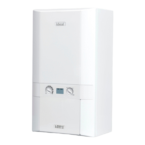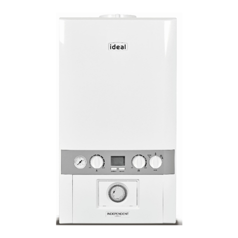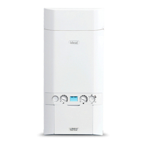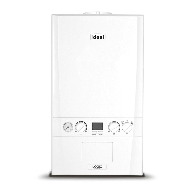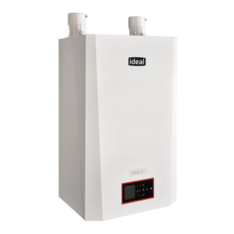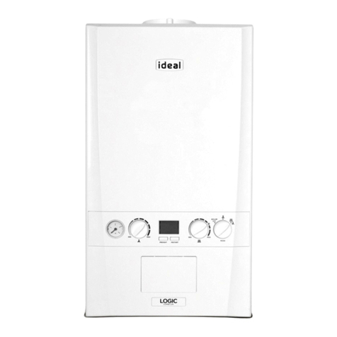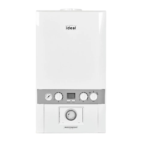
Ideal Logic Combi - Installation and Servicing
GENERAL
2.
3.
4.
5.
6.
IMPORTANT
TERMINAL
AIR SUPPLY
WATER CIRCULATION SYSTEM
IMPORTANT.
WATER TREATMENT - see Frame 5
BOILER CONTROL INTERLOCKS
ELECTRICAL SUPPLY
WARNING.
CONDENSATE DRAIN )
no
other materials may be used.
IMPORTANT.
* Only one reduction down to 25mm is allowable per installation
otherwise BS5440-1 2008 dimensions must be followed.
Flue Terminal Positions
Min. Spacing*
1.
2.
BS5440-1 2008 75mm (3”)
3.
BS5440-1 2008 200mm (8”)
4.
BS5440-1 2008 200mm (8”)
5.
BS5440-1 2008 150mm (6”)
6.
BS5440-1 2008 300mm (12”)
7.
8.
9.
10.
11.
12.
Vertical Terminals
13.
14.
15.
16.
Table 4 - Balanced Flue Terminal Position
204626-8.indd 9 25/08/2011 13:15:22
