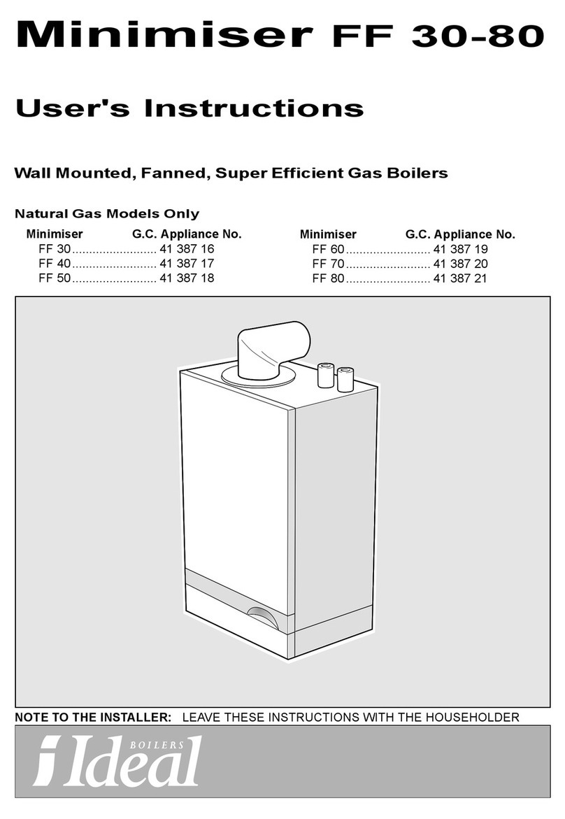
manuals.online logo
Brands
  1. Home
  2. •
  3. Brands
  4. •
  5. IDEAL
  6. •
  7. Boiler
  8. •
  9. IDEAL MINI C28 User manual

IDEAL MINI C28 User manual

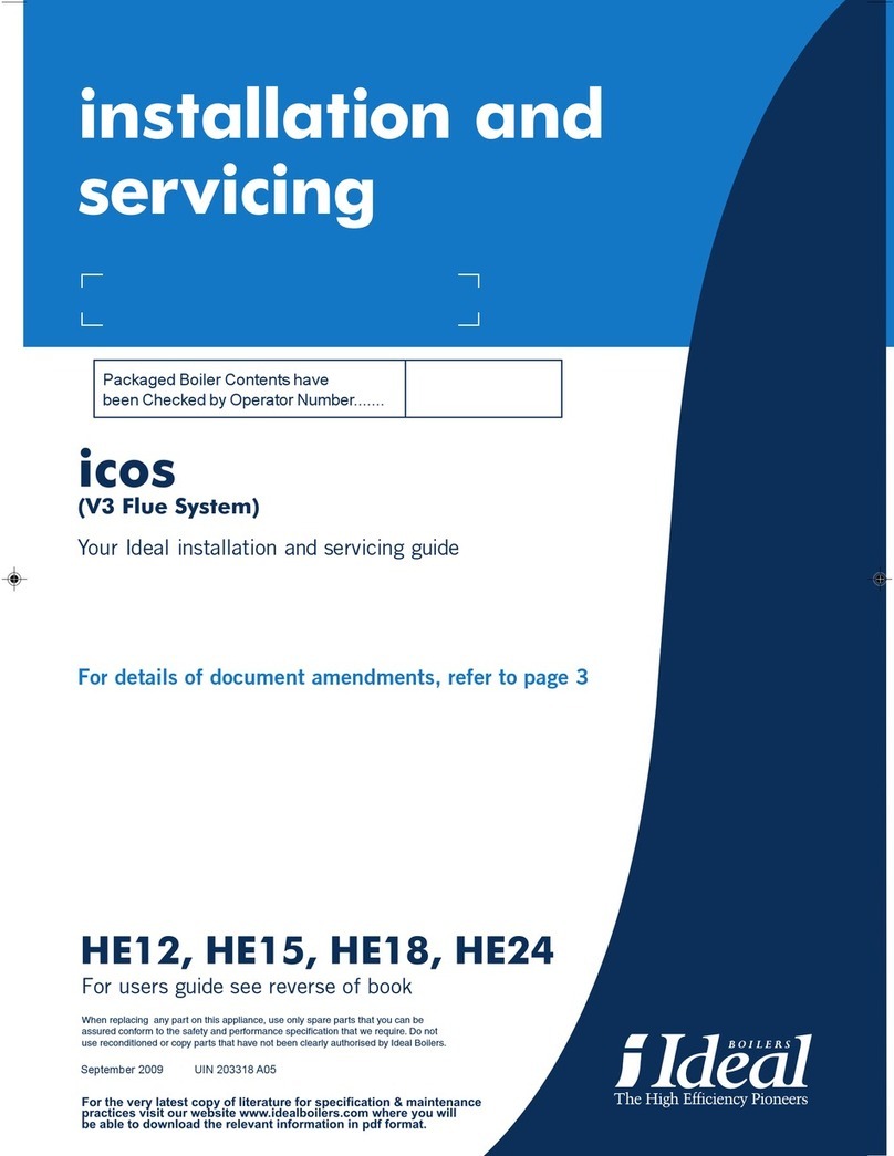
installation and
servicing
mini
YourIdeal installation and servicing guide
C24/C28/C32
S24/S28
Whenreplacing anypartofthisappliance,useonlysparepartsthatyoucanbe
assuredconformtosafetyand performancespecificationthatwerequire.Donotuse
reconditionedorcopypartsthathavenotbeenclearlyauthorised byIdealBoilers
GENERAL
2Mini--- Installation&Servicing
Table1--- BoilerData
MiniC24 MiniC28 MiniC32 MiniS24 MiniS28
Gas supplytype&connectionII2H3PG20 20mbar,G31 37mbar,22 mm copper
Inlet/Outletconnection--- DomesticHotWater15 mm copper---
Flow&returnconnection--- CentralHeating22 mm copper
Flueterminaldiametermm (in.)100 (4)
Maxworkingpressure
(sealedsystem)bar(lb/in2)3.0(43.5)
MaxDHWwaterinletpressurebar(lb/in2)10.0(145.0)---
MinDHWwaterinletpressurebar(lb/in2)0.3(4.4)---
Electricalsupply230 Vac50 Hz
MaxpowerconsumptionW150 170 180 150 170
Externalfuserating3A
InternalfuseratingT2A
Watercontent--- CHlitre(gal.)1.0(0.22)1.1(0.242)1.0(0.22)1.1(0.242)
Watercontent--- DHWlitre(gal.)0.2(0.044)---
Dryweightkg(lb.)37 (81.6)39 (86.0)39 (86.0)36 (79.4)38 (83.8)
Size:Height/Width/Depthmm (in.)703 (27 11/16”)/400 (15 3/4”)/310 (12 3/16”)
Liftweightkg(lb.)35.5(78.4)36.5(80.6)36.5(80.6)34.5(76.2)35.5(78.4)
Table2--- PerformanceData--- CentralHeating
MiniC24
MiniS24
MiniC28
MiniS28
MiniC32
MaxMinMaxMinMaxMin
Burnerpressure(Hot)G20
G31 mbar
(in.w.g.)11.7(4.7)
35.7(14.3)1.8(0.7)
6.1(2.4)11.7(4.7)
35.7(14.3)1.2(0.5)
5.7(2.3)10.5(4.2)
35.7(14.3)1.5(0.6)
6.7(2.7)
Inputbasedon nett CVkW
(btu/h)26.60
(90 759)11.00
(37 532)31.10
(106 113)13.00
(44 356)35.20
(120 102)15.50
(52 886)
Inputbasedongross CVkW
(btu/h)29.52
(100 732)12.21
(41 656)34.52
(117 773)14.43
(49 230)39.07
(133 306)17.20
(58 686)
OutputkW
(btu/h)24.30
(82 912)9.10
(31 049)28.36
(96 764)11.00
(37 532)32,00
(109 184)12,73
(43 435)
Gasconsumption(Hot)G20
G31 l/s(ft3/h)
l/s0.763 (97.0)
0.309 0.315 (40.1)
0.128 0.892 (113.5)
0.361 0.373 (47.4)
0.151 1.035 (131.7)
0.400 0.456 (58.0)
0.176
Seasonalefficiency*(SEDBUK)
%BandD
78.2BandD
78.3BandD
79.4
*ThevalueisusedintheUKGovernment’sStandardAssessmentProcedure(SAP)forenergyratingofdwellings.
Thetestdatafromwhichithasbeencalculatedhavebeencertified byanotified body.
Table3--- PerformanceData--- DomesticHotWater
MiniC24 MiniC28 MiniC32
Maximum
Burnerpressure(Hot)G20
G31 mbar
(in.w.g.)11.7(4.7)
35.7(14.3)11.7(4.7)
35.7(14.3)10.5(4.2)
35.7(14.3)
Inputbasedon nett CVkW(btu/h)26.60 (90 759)31.10 (106 113)35.20 (120 102)
Inputbasedongross CVkW(btu/h)29.52 (100 732)34.52 (117 773)39,07 (133 306)
OutputkW(btu/h)24.30 (82 912)28.36 (96 764) 32,00 (109 184)
Gasconsumption(Hot)G20
G31 l/s(ft3/h)
l/s0.763 (97.0)
0.309 0.892 (113.5)
0.361 1.035 (131.7)
0.400
Flow35 °Ctemp.risel/m(gpm)10.0(2.2)11.6(2,6)13.1(2.9)
Domestichotwaterspecific
ratel/m(gpm)11.6(2.6)13.6(3,0)15.3(3.4)
Note:thegasconsumptioniscalculatedusingacalorific
valueof38.7MJ/m3(1038 Btu/ft3)gross or34.9MJ/m3(935
Btu/ft3)nett.
To obtainthegasconsumptionatdifferentcalorificvalue:---
a.FORL/S--- dividethegross heatinput(kW)bythegross
C.V.ofthegas(MJ/m3)
b.FORFT3/H--- dividethegross heatinput(Btu/h)bythe
gross C.V.ofthegas(Btu/ft3)
KeytoSymbols:
IE=Ireland,GB=UnitedKingdom(Countriesofdestination)
PMS=Maximumoperatingpressureofwater
C12 C32 C52 =aroomsealedappliancedesignedfor
connectionviaconcentricductstoahorizontalorvertical
terminalortwinfluesystem.
II2H3P=appliancedesignedforuseon2ndfamilygasgroup
Hor3rdfamilygasgroup3P
CAUTION. Toavoidthepossibilityofinjuryduringtheinstallation,servicingorcleaning
ofthisappliancecareshould betakenhandling edgesofsheetsteelcomponents.
GENERAL
MiniInstallation&Servicing3
Mini
MiniC24 G.C.applianceNo.47---348 ---18
MiniC28 G.C.applianceNo.47---348 ---19
MiniC32 G.C.applianceNo.47---348 ---25A
MiniS24 G.C.applianceNo.41---392 ---98
MiniS28 G.C.applianceNo.41---392 ---99
PINo.0694BM3420
Destinationcountries:GB,IE
CONTENTS
Airsupply7
Boilerclearances4
Boilerexplodedview11
Electricalconnections17
Electricalsupply8
Faultfinding47
Flow wiringdiagram22
Fluefitting13
Gasconversion27
Gas safetyregulations5
Gas supply6
Installation12
Mandatoryrequirements5
Replacementofcomponents32
Servicing28
Shortlistofparts54
Thermostaticradiatorvalves9
Waterconnections16
Watertreatment7
Wiringdiagrams18
ForGB,tocomplywithBuildingRegulationsPartL1(PartJinScotland)theboilershould befittedinaccordancewiththe
manufacturer’sinstructions.Self---certificationthat theboilerhasbeeninstalledtocomplywithBuildingRegulationscanbe
demonstrated bycompletingandsigningtheBenchmarklogbook.
BenchmarkLogBookDetails
BoilerPage
Makeandmodel3
Applianceserialno.ondatabadge11
SEDBUKNo.%2
Controls
Timeandtemperaturecontroltoheating23/24
Timeandtemperaturecontroltohotwater24
Heatingzonevalves23
TRV’s9
Autobypass 9
Boilerinterlock9
Forall boilers
FlushingtoBS.7593 7
Inhibitor7
Centralheatingmode
Heatinput tobecalculated
BoilerPage
Burneroperatingpressuremeasureandrecord
Centralheatingflowtemp.measureandrecord
Centralheatingreturntemp.measureandrecord
Forcombinationboilersonly
Scalereducer9
Hotwatermode
Heatinput tobecalculated
Max.operatingburnerpressuremeasureandrecord
Max.operatingwaterpressuremeasureandrecord
Coldwaterinlet tempmeasureandrecord
Hotwateroutlet temp.measureandrecord
Waterflowrateatmax.settingmeasureandrecord
Forcondensingboilersonly
Condensatedrain n/a
Forall boilers:complete,sign&handovertocustomer
Forassistancesee TechnicalHelplineonthebackpage
NOTETOTHE INSTALLER:leave these
instructionsadjacent to the gasmeter.
Alsocompletethebenchmark logbookandgive
thisto thecustomer
GENERAL
Mini--- Installation&Servicing
4
1BOILER WATER CONNECTION
65 (2 9/16”)
85 (3 5/16”)
255 (10”)
561 (22 1/16”)101 (4”)
83 (3 1/4”)
65 (2 9/16”)
52 (2”)
64 (2 1/2”)
Wall
mounting
plate
CHreturn
CHflow
DHWhotoutlet*
DHWcoldinlet*
Gasinlet
20 (3/4”)
PipesizeO.D.mm
CHflow22
CHreturn22
Gasinlet22
DHWcoldinlet*15
DHWhotoutlet*15
*Pipeconnectionsnotusedonsystemboilers
2BOILER CLEARANCES
All dimensionsinmm (in.)
Thefollowingminimumclearancesmustbemaintainedfor
operationandservicing.Additionalspacewill berequiredfor
installation,dependinguponsiteconditions.
25 (1”)50 (2”)
200 (7 7/8”)
200 (7 7/8”)
Bottomclearance
Thebottomclearance,afterinstallation,canbereducedto
20mm.However,200mm mustbeavailableforservicing.
Frontclearance
Theminimumfrontclearancewhenbuiltintoacupboardis
50mm (2”)fromthecupboard door.However450mm
(17 3/4”)overall clearanceis still required,withthecupboard
dooropen,toallowforservicing.
SideandRearFlue
a.Providedthat theflueholeiscutaccurately,e.g.withacore
drill,thefluecanbeinstalledfrominsidethebuildingwhere
wall thickness doesnotexceed600 mm (24”).
Wherethespaceintowhichtheboilerisgoingtobeinstalled
isless thanthelengthof fluerequiredthefluemustbefitted
fromtheoutside.
installationfrominsideONLY
b.Ifacoreboringtoolistobeusedinsidethebuildingthe
spaceinwhichtheboileristobeinstalledmustbeatleast
wide enoughtoaccommodatethetool.
147 (5 3/4”)
92 (3 5/8”)
200 (7 7/8”)200 (7 7/8”)
GENERAL
MiniInstallation&Servicing5
INTRODUCTION
MiniC24,MiniC28 and MiniC32 arewall mounted,low
watercontent, balanced fluecombinationgasboilers.
MiniS24 and MiniS28 arewall mounted,low watercontent,
balanced fluesystemgasboilers.
Centralheating(CH)outputand domestichotwater(DHW)
output(oncombinationversions)arebothfullymodulating:
--- between9.10 (31 049)and24.30 (82 912)kW(btu/h)for
modelMiniC24 andMiniS24;
--- between11.00 (37 532)and28.00 (95 536)kW(btu/h)for
modelMiniC28 andMiniS28.
--- between12.73 (43 435)and32.00 (109 184)kW(btu/h)for
modelMiniC32.
Theboilersaresuitableforconnectiontofullypumped,
pressurisedsealedwatersystemsONLY.
Asystembypass isnotrequiredwhenTRV’sarefittedtoall
radiators(see Frame5).Theboilerincorporatesanautomatic
bypass.
Acirculatingpump,pressuregauge,safetyvalveandheating
expansionvesselsareprovided.
TheCHflowtemperatureiscontrolled byanelectronic
thermostat.InDHWmodetheboilermodulatestosustaina
nominaladjustablewaterflowtemperatureof55 °C.
Theboilercasingisofwhitepaintedmildsteelwitha
drop---downcontrolsaccess door.
Theboilertemperaturecontrolislocated behindthecontrol
paneldoor.
Themain heatexchangerismadeofcopper.
TheDHWheatexchangeris stainless steel.
Thesystempipeworkmustincludedraincocksinappropriate
places.Pipeworkmaybetakendownwards.
Forupwardspipeworkinstallationanadditionalframe
(optional)mustbeused(see frame18).
OPTIONALEXTRAKITS
ProgrammerKit(MiniC24,MiniC28,MiniC32 only)fits
neatlywithinthecasing.Separatefittinginstructionsare
includedwiththekit.Note.Ifusinganalternativeprogrammer
readFrame26 first.
HorizontalConcentricExtensionDucts
Upto4m(13’1”) for models:
MiniC24,MiniS24,MiniC28,MiniS28.
Upto2,7m(8’10”) for modelMiniC32
Otheravailablekitsarelistedinframe9.
DHWOPERATION(combiversions)
With nocall forCHtheboilerfiresonlywhenDHWisdrawn
off.Whenthereisacall forCH,theheatingsystemis supplied
at theselectedtemperatureuntilDHWisdrawnoff.The
outputisthendirected bythedivertervalvetoheat the
secondaryheatexchangerandsupplyamaximumdraw---off
of:
MiniC24.10.0(2.2)l/min(gpm) at35 degree rise.
MiniC28 11.6(2.6)l/min(gpm) at35 degree rise.
MiniC32 13.1(2.9)l/min(gpm) at35 degree rise.
ThenominalDHWtemperatureis55 °C,butwaterdrawnoff
whentheboilerhasbeenonforcentralheatingmaybehotter
thanthis,forashortperiodoftime.
GAS SAFETY
CurrentGasSafety(InstallationandUse)
Regulationsor rulesinforce
Theapplianceis suitableonlyforinstallationinGBandIEand
should beinstalledinaccordancewiththerulesinforce.
InGB,theinstallationmustbecarriedoutbyaCORGI
RegisteredInstaller.Itmustbecarriedoutinaccordancewith
therelevantrequirementsofthe:
FGasSafety(InstallationandUse)Regulations
FTheappropriateBuildingRegulationseitherTheBuilding
Regulations,TheBuildingRegulations(Scotland),
BuildingRegulations(NorthernIreland).
FTheWaterFittingsRegulationsorWaterbyelawsin
Scotland.
FTheCurrentI.E.E.WiringRegulations.
Wherenospecificinstructionsaregiven,referenceshould be
madetotherelevantBritishStandardCodeofPractice.
InIE,theinstallationmustbecarriedoutbyaCompetent
Personandinstalledinaccordancewiththecurrenteditionof
I.S.813 ”DomesticGasInstallations”,thecurrentBuilding
Regulationsandreferenceshould bemadetothecurrent
ETCIrulesforelectricalinstallation.
Detailedrecommendationsarecontainedinthefollowing
BritishStandardCodesofPractice:
BS5440:1Flues(forgasappliancesofratedinputnot
exceeding70 kW).
BS5440:2Ventilation(forgasappliancesofratedinput
notexceeding70 kW).
BS.5449 Forcedcirculation hotwatersystems.
BS.5546 Installationofgashotwatersuppliesfor
domesticpurposes(2ndFamilyGases)
BS6700 Design,installationtestingandmaintenanceof
services supplyinghotwaterfordomesticuse.
BS.6798 Installationofgasfiredhotwaterboilersof
ratedinputnotexceeding70 kW.
BS.6891 Lowpressureinstallationpipes.
Health&SafetyDocumentNo.635.
TheElectricityatWorkRegulations,1989.
ThemanufacturersnotesmustNOTbetaken,inanyway,as
overridingstatutoryobligations.
IMPORTANTTheseappliancesareCEcertificatedforsafety
and performance.Itis,therefore,important thatnoexternal
controldevices,e.g.fluedampers,economisersetc., are
directlyconnectedtotheseappliancesunless covered by
theseInstallationandServicingInstructionsorasotherwise
recommended byCaradonIdealLtd.inwriting.Ifindoubt
please enquire.
Anydirectconnectionofacontroldevicenotapproved by
CaradonIdealLtd.couldinvalidatethecertificationandthe
normalappliancewarranty.ItcouldalsoinfringetheGas
SafetyRegulationsandtheaboveregulations.
SAFE HANDLINGOFSUBSTANCES
Careshould betakenwhen handlingtheboilerinsulation
panels,whichcancauseirritationtotheskin.Noasbestos,
mercuryorCFCsareincludedinanypartoftheboilerinits
manufacture.
GENERAL
Mini--- Installation&Servicing
6
LOCATIONOFBOILERANDFLUEOUTLET
Theboilermustbeinstalledonaflatandverticalwall,capable
ofadequatelysupportingtheweightoftheboilerandany
ancillaryequipment.
Theboilermaybefittedonacombustiblewall andinsulation
betweenthewall andtheboilerisnotnecessary,unless
required bythelocalauthority.
Theboilermustnotbefittedoutside.
TimberFramedBuildings
Iftheboileristobefittedinatimberframed buildingitshould
befittedinaccordancewiththeInstituteof GasEngineers
documentIGE/UP/7,1998.
BathroomInstallations
Theboilermaybeinstalledinanyroomorinternalspace,
althoughparticularattentionisdrawntotherequirementsof
thecurrentI.E.E.(BS.7671)WiringRegulationsand,in
Scotland,the electricalprovisionsofthebuildingregulations
applicableinScotlandwithrespect totheinstallationofthe
boilerinaroomorinternalspacecontainingabathorshower.
ForIrelandreferenceshould bemadetothecurrentETCI
rulesforelectricalinstallationsandI.S.813:2002
Wherearoomsealedapplianceisinstalledinaroom
containingabathorshowerthentheapplianceandany
electricalswitchorappliancecontrolutilisingmainselectricity
should besosituatedthatitcannotbetouched byaperson
usingthebathorshower.
Note.Itisnotpermissibletoinstall amains socketina
bathroom.
Whereinstallationwill beinan unusual location,special
proceduresmaybenecessaryandBS6798 givesdetailed
guidanceonthisaspect.
CompartmentInstallations
Acompartmentusedtoenclosetheboilershould be
designedandconstructedspeciallyforthispurpose.
Anexistingcupboardorcompartmentmaybeused,provided
thatitismodifiedforthepurpose.
Inbothcasesdetailsofessentialfeaturesofcupboard/
compartmentdesign,includingaircupboardinstallation,are
toconformtothefollowing:
FBS6798 (Nocupboardventilationisrequired--- see “Air
supply”fordetails)
FThepositionselectedforinstallationMUSTallow
adequatespaceforservicinginfrontoftheboiler.
FFortheminimumclearancesrequiredforsafetyand
subsequentservice,see thewall mountingtemplateand
frame2.Inaddition,sufficientspacemayberequiredto
allowliftingaccess tothewall mountingplate.
GAS SUPPLY
Thelocalgas suppliershould beconsulted,at theinstallation
stage,inordertoestablishtheavailabilityofanadequate
supplyofgas.AnexistingservicepipemustNOTbeused
withoutpriorconsultationwiththelocalgas supplier.
Naturalgasboilersmustbeinstalledonagas supplywitha
governedmeter.Agasmetercanonlybeconnected bythe
localgas supplierorbyaregisteredCORGIengineer.
PropanegasboilersMUSTbeinstalledwithpipes,cylinders
and pressureregulatorsfittedinaccordancewithBS.5482.1.
BulktankinstallationsMUSTcomplywiththeHomeOffice
codeofpracticeforstorageofliquefied petroleumgasatfixed
installations.ThecompleteinstallationMUSTbetestedfor
gas soundness and purgedasdescribedintheabovecode.
Theboilerisadjustedat thefactoryforusewiththerelevant
supplygas.Aworking gaspressure equaltothatstatedin
Table1MUSTbeavailableat theboilerinlet.
Whereapplicable,theappliancecanbeconvertedfor
G20---NaturalGasorG31---PropaneGasbyusingthe
appropriateconversionkit.
IMPORTANTInstallationpipesMUSTbefittedinaccordance
withBS.6891.InIErefertoI.S.813.2002.
PipeworkfromthemetertotheboilerMUSTbeofan
adequatesize,i.e.notless than22 mm O.D.copperor3/4”
BSPiron.
FLUEINSTALLATIONREQUIREMENTS
Thefluemustbeinstalledinaccordancewiththe
recommendationsofBS.5440---1 2000.
InIErefertoI.S.813.2002.
Thefollowingnotesareintendedforgeneralguidance.
1TheboilerMUSTbeinstalledsothat theterminalis
exposedtoexternalair.
2Itisimportant that thepositionoftheterminalallowsthe
free passageofairacross itatall times.
3Minimumacceptablespacingfromtheterminalto
obstructionsandventilationopeningsarespecifiedin
Table4.
4Wherethelowestpartoftheterminalisfittedless than2m
(6’6”)aboveabalcony,abovegroundoraboveaflatroof
towhichpeoplehaveaccess thentheterminalMUSTbe
protected byapurposedesignedguard.
Ensurethat theguardisfittedcentrally.
5Wheretheterminalisfittedwithin850mm (34”)ofaplastic
orpaintedgutteror450mm (18”)ofpaintedeavesthenan
aluminiumshieldatleast750mm (30”)longshould be
fittedtotheundersideofthegutterorpaintedsurface
fittedcentrallyabovetheflue.
6Theairinlet/productsoutletductandtheterminalofthe
boilerMUSTNOTbecloserthan25mm (1”)to
combustiblematerial.Detailedrecommendationsonthe
protectionofcombustiblematerialaregiveninBS.
5440---1:2000.InIErefertoI.S.813.2002.
Table4--- Balancedflueterminalposition
TerminalpositionMinimumspacing
1Directlybelow,aboveoralongside
ofanopenablewindow,airventor
otherventilationopening
300 mm (12”)
2Belowguttering,drainpipesorsoil
pipes75 mm (3”)
3Beloweaves200 mm (8”)
4Belowbalconiesoracarportroof650 mm (26”)
5Fromverticaldrainpipesorsoil
pipes75 mm (3”)
6Fromaninternalorexternalcorner
ortoaboundaryalongsidethe
terminal
300 mm (12”)
7Aboveadjacentground,roofor
balconylevel300 mm (12”)
8Fromasurfaceoraboundary
facingtheterminal.600 mm (24”)
9Fromaterminalfacingaterminal1200 mm (48”)
10 Fromanopeninginacarport(e.g.
doororwindow)intodwelling1200 mm (48”)
11 Verticallyfromaterminalonthe
samewall 1500 mm (60”)
12 Horizontallyfromaterminalonthe
wall 300 mm (12”)
GENERAL
MiniInstallation&Servicing7
VerticalTerminals
13 Abovetheroofpitchwithroof
slopeofall angles.
Aboveflatroof
300 mm (12”)
300 mm (12”)
14 Fromsinglewall face
Fromcornerwall faces
600 mm (24”)
1000 mm (40”)
TwinFlueApplications
15 Centredistancebetweenairinlet
andflueoutletducts120mm (5”)
Terminalsguardsareavailablefromboilersuppliers--- askfor
TowerFlueGuard,ModelK6.Incaseofdifficultyseekadvice
from:
GrasslinUKLtd.,Towerhouse,ValeRise,Tonbridge,
KentTN9 1TBTel.+44 (0)1732 359 888 FaxNo.+44 (0)
1732 354 455 www.tfc---group.co.uk
IMPORTANTItisabsolutelyESSENTIALtoensure,in
practice,thatproductsofcombustiondischargingfromthe
terminalcannotre---enterthebuildingoranyotheradjacent
buildingthroughventilators,windows,doorsothersourcesof
naturalairinfiltration,orforcedventilation/airconditioning.
Ifthis shouldoccurtheapplianceMUSTbeturnedOFF,
labelledas“unsafe”untilcorrectiveactiontaken.
AIRSUPPLY
ItisNOTnecessarytohaveapurpose---providedairventin
theroomorinternalspaceinwhichtheboilerisinstalled.
Neitherisitnecessarytoventilateacupboardor
compartmentinwhichtheboilerisinstalled,duetothelow
surfacetemperaturesoftheboilercasingduringoperation;
thereforetherequirementsofBS6798,Clause12,BS5440:2
andinIEI.S.813:2002 maybedisregarded.
WATER CIRCULATIONSYSTEM
Theboilersaredesignedforconnectiontopressurised,fully
pumped,sealedwatercentralheatingsystemsONLY.The
domestichotwater(DHW)calorifierisincorporatedwithinthe
combiboilerandonlyrequiresconnectiontothemainswater
supply.
AdditionalPumps.
Theboileris suppliedwithanintegralcirculatingpump.Ifthe
boileristobeusedinconjunctionwithanyadditional
circulatingpumps,pleasecontact theTechnicalHelplinefor
adviceonapplication.
IMPORTANT
Aminimumlengthof1mofcopperpipeMUSTbefittedto
bothflowandreturnconnectionsfromtheboilerbefore
connectiontoanyplasticpiping.
Ensurethat themainswatersupplypressureisadequateto
providetherequiredDHWflowrate.RefertoTable1on
page2.
Thecentralheatingsystemshould beinaccordancewithBS.
6798 and,inaddition,forsmallboreandmicroboresystems
BS.5449.
Thedomestichotwatersystemshould beinaccordancewith
BS.5546 andBS.6700.
CoppertubingtoBS2871:1isrecommendedforwater
carryingpipeworkandMUSTbeusedforpipeworkcarrying
potablewater.
AnysolderedjointsonpotablewaterpipeworkMUSTNOTbe
madewithsoldercontaininglead.
Ancillarypipeworknotformingpartoftheusefulheating
surfaceshould belaggedtopreventheatloss andany
possiblefreezing--- particularlywherepipesrun throughroof
spacesorventilatedunderfloorspaces.
Drainingtaps should beatleast1/2”BSPnominalsizeand
beinaccordancewithBS2879.
WATER TREATMENT
CentralHeating
Antifreezefluid,corrosionandscaleinhibitorfluids suitablefor
usewithboilershavingcopperheatexchangersmaybeused
inthecentralheatingsystem.
IMPORTANT
Theapplicationofanyothertreatment tothisproduct
mayrendertheguarantee ofCaradonIdealLimited
INVALID.
CaradonIdealLimitedrecommendWaterTreatmentin
accordancewiththeBenchmarkGuidanceNotesonWater
TreatmentinCentralHeatingSystems.
CaradonIdealLimitedrecommendtheuseofFernox,GE
BetzSentinelorSalamanderwatertreatmentproducts,which
mustbeusedinaccordancewiththemanufacturers
instructions.
Notes.
1.Itismostimportant that thecorrectconcentrationofthe
watertreatmentproductsismaintainedinaccordancewith
themanufacturers’instructions.
2.Iftheboilerisinstalledinanexistingsystemanyunsuitable
additivesMUSTberemoved bythoroughcleansing.
BS7593:1992 detailsthestepsnecessarytocleana
domesticheatingsystem.
3.Inhardwaterareas,treatment topreventlimescalemaybe
necessary--- however,theuseofartificiallysoftenedwateris
NOTpermitted.
4.Undernocircumstances shouldtheboilerbefired before
thesystemhasbeenthoroughlyflushed.
DomesticHotWater
In hardwaterareaswheremainswatercanexceed200ppm
TotalHardness (asdefined byBS7593:1993 Table2)ascale
reducingdeviceshould befittedintotheboilercoldsupply
withintherequirementsofthelocalwatercompany.Theuse
ofartificiallysoftenedwater,however,isNOTpermitted.
CaradonIdealLimitedrecommendtheuseofFernox
Qantomat,GEBetzSentinelCombiguardandCalmag
CalPhosIscalereducingdevices,whichmustbeusedin
accordancewiththemanufacturers’instructions.
Forfurtherinformationcontact:
Fernox
CooksonElectronics
ForsythRoad
Sheerwater
Woking
Surrey
GU21 5RZ
+44 (0)1799 550811
GEBetz
SentinelDivision
FoundryLane
Widnes
Cheshire
WA8 8UD
+44 (0)151 420 9563
Salamander(Eng)Ltd
ReddicapTradingEstate
SuttonColdfield
WestMidlands
B75 7BY
+44 (0)121 378 0952
CalmagLtd
TowerView
CaltonRoad
Keighley
WestYorkshire
BD21 4UT
+44 (0)1535 210320
GENERAL
Mini--- Installation&Servicing
8
3ELECTRICALSUPPLY
Warning.Thisappliancemustbe efficientlyearthed.
WiringexternaltotheapplianceMUSTbeinaccordancewith
thecurrentI.E.E.(BS.7671)WiringRegulationsandanylocal
regulationswhichapply.ForIrelandreferenceshould be
madetothecurrentETCIrulesforelectricalinstallations.
Thepointofconnectiontothemains should bereadily
accessibleandadjacent totheboiler,exceptforbathroom
installationswherethepointofconnectiontothemainsMUST
besituatedoutsideofthebathroom.
Note.Wherearoomsealedapplianceisinstalledinaroom
containingabathorshowerthentheapplianceandany
electricalswitchorappliancecontrolutilisingmains
electricityshould besosituatedthatitcannotbetouched by
aperson usingthebathorshower.
4 SEALED SYSTEMREQUIREMENTS
CentralHeating
Note.Miniboilersaresuitableforfullypumped pressurised
sealedsystemsonly.
REQUIREMENTS
1General
Theinstallationmustcomplywiththerequirementsof
BS.6798 andBS.5449.
2FlowTemperature
Theinstallationshould bedesignedtoworkwithflow
temperaturesofupto90 °C.
3WorkingPressure
All componentsofthesystem mustbesuitableforaworking
pressureof3bar(45 lb/in2)andtemperatureof110 °C.Extra
careshould betakeninmakingall connections sothat the
riskofleakageisminimised.
Thefollowingcomponentsareincorporatedwithinthe
appliance:
a.Circulatingpump.
b.Safetyvalve;withanon---adjustablepre---setliftpressureof
3bar(45lb/in2).
c.Pressuregauge;coveringarangeof0---4bar.
d.6litre expansionvessel;withaninitialchargepressureof
0.7bar(10.5lb/in2).
ForfurtherdetailsrefertoBS.5449:1andtheBritishGas
Corporationpublication’SpecificationsforDomesticCentral
HeatingandHotWater’.
4Fillingthesystem
Fill thesystemthroughatemporaryhoseconnectionfroma
draw---off tapsuppliedfromaservicepipeundermains
pressure.Wherethemainspressureisexcessiveapressure
reducingvalveshall beusedtofacilitatefilling.
Wheninstallingthefillingconnectionprovidedwiththeboiler
anadditionalWRASapprovedvalvemustbefittedtothe
mainswatersupplyupstreamofthedoublecheckvalveto
fullycomplytheWaterRegulations
CHreturn
HoseunionsMains
Water
Supply
Temporaryhose
(disconnect
afterfilling)
StopvalveAdditionalstopvalve
Doublecheckvalve
assembly
Notedirectionof flow
Systemfillingandmake---up
Proceedwiththefollowing:
FThoroughlyflushout thewholeofthesystemwithcold
waterbeforefittingtheboiler.
FFill andvent thesystemuntilthepressuregaugeregisters
1.5bar(22 lb/in2).Examineforleaks.
FReleasewaterfromthesystemuntilapressureof1bar
(15 lb/in2)isreached.
Toavoidgettingdebrisonthevalveseat,donotuse
thesafetyvalvetodothis.
FLight theboilerandheat thesystemtothemaximum
workingtemperature.Examineforleaks.
FTurnoff theboilerand drainthesystemwhilestill hot.
FRefill andvent thesystem.
FRe---pressurisethesystemtothedesiredchargepressure
(see Table5).
Table5MiniC24,MiniS24,MiniC28,MiniS28
Systemchargepressure
(bar)0.5 0.7 1.0
Safetyvalvesetting3.0
Vesselpre---chargepressure
(bar)0.7
Systemvolume(litres)Volumeofexpansionvessel
inadditionto6litreunit
fittedtoboiler
75 --- --- ---
100 0.3 0.8 1.4
125 1.8 2.5 3.2
150 3.4 4.2 5.0
175 5.0 6.0 7.0
200 6.5 7.6 8.7
225 8.1 9.3 10.6
250 9.6 11.1 12.4
275 11.2 12.8 14.3
300 12.8 14.5 16.1
Multiplythisfactorby
systemvolumeand deduct
6litresto obtainsizeof
additionalvesselforother
systemvolumes.
0.063 0.069 0.074
5Sizeofexpansionvessel
Forthesystemwaterexpansiontobecontained bythe6litre
expansionvesselfittedtothefollowingmodels:
MiniC24,MiniS24,MiniC28,MiniS28
thecoldsystemvolumemustnotexceed:
96 litreswhenpressurisedto0.5bar(cold)
88 litreswhenpressurisedto0.7bar(cold)
81 litreswhenpressurisedto1.0bar(cold)
Ifthepressure exceeds2.65 barwhentheboilerisupto
temperaturewithall radiatorsin usethenanadditional
expansionvesselMUSTbeinstalledonthereturnpipework.
Forexpansionvolumes see Table5.
GENERAL
MiniInstallation&Servicing9
Table6MiniC32
Systemchargepressure
(bar)0.5 0.7 1.0
Safetyvalvesetting3.0
Vesselpre---chargepressure
(bar)0.7
Systemvolume(litres)Volumeofexpansionvessel
inadditionto7litreunit
fittedtoboiler
75 --- --- ---
100 --- --- 0.4
125 0.8 1.6 2.3
150 2.5 3.4 4.1
175 4.0 5.1 6.0
200 5.6 6.8 7.8
225 7.2 8.6 9.7
250 8.8 10.3 11.5
275 10.3 12.0 13.4
300 11.9 13.7 15.2
Multiplythisfactorby
systemvolumeand deduct
7litresto obtainsizeof
additionalvesselforother
systemvolumes.
0.063 0.069 0.074
Forthesystemwaterexpansiontobecontained bythe7litre
expansionvesselfittedtothefollowingmodel:
MiniC32
thecoldsystemvolumemustnotexceed:
111 litreswhenpressurisedto0.5bar(cold)
101 litreswhenpressurisedto0.7bar(cold)
95 litreswhenpressurisedto1.0bar(cold)
Ifthepressure exceeds2.65 barwhentheboilerisupto
temperaturewithall radiatorsin usethenanadditional
expansionvesselMUSTbeinstalledonthereturnpipework.
Forexpansionvolumes see Table6.
GuidanceonvesselsizingisgiveninBS7074:1andBS5449
ForIErefertothecurrenteditionofI.S.813.
6HydraulicLoss
Remainingpumpcapacity
Flowratel/hour
mH2O
0
1
2
3
4
5
6
0 200 400 600 800 1000 1200 1400
7Drainingthesystem
DrainingtapsMUSTbelocatedinaccessiblepositionsto
permit thedrainingofthewholecentralheatingsystem,
includingthecentralheatingsideoftheboiler.Thetaps
should beatleast1/2”BSPnominalsizeand bein
accordancewithBS2879.
5BOILER CONTROLINTERLOCKS
Thermostaticradiatorvalves.
CaradonIdealLtd.support therecommendationsmadeby
leadingmanufacturersofdomesticheatingcontrolsthat
heatingsystemsutilisingfull thermostaticradiatorvalve
controloftemperatureinindividualrooms shouldalsobe
fittedwitharoomthermostatcontrollingthetemperatureina
spaceserved byradiatorsnotfittedwithsuchavalveas
statedinBS5449.Suchanarrangementwill providefora
more efficientcontrolofthe environmentandwill alsoavoid
thecontinuousrunningofthecirculationpump during
programmedheatingONperiods,savingelectricalenergy.
Itisthereforestronglyrecommendedthat,whenthermostatic
radiatorvalvesareused,thespaceheatingtemperature
controloveraliving/diningareaorahallway,havingaheat
requirementofatleast10%oftheboileroutput,isachieved
usingaroomthermostatwhilstother roomsareindividually
controlled bythermostaticradiatorvalvesas statedin
BS5449.
Forfurtherinformationreferto“GoodPractiseGuide143”a
publicationofthe energyefficiencyoffice,availablefromthe
buildingresearchestablishmentGarstonWatfordWD2 7JR
tel:+44 (0)1923 664258
Theboilerisfittedwithanautomaticinternalbypass.No
furthersystembypass isrequired.
Typicalinstallation
DA
TRV
B
Room
T/stat
Balancingvalve
TRV
TRV
6 DOMESTICHOT WATER
REQUIREMENTS
1Thedomestichotwaterservicemustbeinaccordance
withBS5546 andBS6700.
2Fortheminimumandmaximumworkingpressuresofthe
MiniC24,MiniC28 andMiniC32 domestichotwater
circuitrefertoTable1,page2.
3Thecoldwatersupplypipeshould beflushed before
fittingtheboiler.
4Theboilersaresuitableforconnectiontomost typesof
washingmachineand dishwashingappliances.
5Whenconnectingtosuitableshowers,i.e.thosedesigned
formodulatingdomestichotwater,ensurethat:
a.Thecoldinlet totheboilerisfittedwithanapproved
anti---vacuumorsyphon non---returnvalve.
b.Hotandcoldsuppliesareofequalpressure.
6Hardwaterareas
Inareaswherethewateris’hard’itisrecommendedthat
aproprietaryscale---reducingdeviceisfittedintotheboiler
coldsupply,withintherequirementsofthelocalwater
company.
GENERAL
Mini--- Installation&Servicing
10
7BOILER WATER CIRCUITDIAGRAM
MiniC24 --- MiniC28 --- MiniC32
32
1
2
34
5
6
7
8
9
10
11
12
13
14
15
16
17
18
19
20
21
23 24
25
22
26
27
28
29
30
31
33
MiniS24 --- MiniS28
33
6
7
8
9
10
11
12
13
14
15
16
17
18
19
20
21
23 24
25
22
26
27
28 29
30
31
1Domestichotwater(DHW)heatexchanger
2Domestichotwater(DHW)flowswitch
3Domestichotwater(DHW)outletpipe
4Domestic coldwaterinletcock
5Three---waydivertervalve
6Maincircuitdrainagecock
7Centralheatingflowcock
8By---pass valve
9Centralheating(CH)returncock
10 3 barpressurereliefvalve
11 Gascock
12 Expansionvessel
13 Gasvalveinletpressuretap
14 Modulating gasvalve
15 Burnerpressuretap
16 Flamedetectionelectrode
17 Ignitionelectrodes
18 Burner
19 Combustionchamber
20 Primaryheatexchanger
21 Fan
22 Airpressureswitch
23 Venturidevice
24 Flueoutletpipe
25 Airintakepipe
26 Automaticairvent
27 Overheat thermostat
28 Pump
29 Pumpventplug
30 Watercircuit temperatureprobe
31 CHflowswitch
32 DHWtemperatureprobe
33 CHcircuit temperature/pressuregauge
INSTALLATION
MiniInstallation&Servicing11
8BOILERASSEMBLY---
Exploded View
18
2
35
12
28
7
9
19
4
1
24 22
5
25
14
17*13
15
16
26
11
10
27*
29*
30
10
31
32
34
33
8
6
3
21
36
2023
1Venturi
2Fan
3Fluehood
4Flamedetectionelectrode
5Overheat thermostat
6Primaryheatexchanger
7Innercasecover
8Ignitionelectrodes
9Heatexchanger returnpipe
10 Thermistor
11 Maincircuitdrainagecock
12 Autoairvent
13 Pump
14 Ignitionpcb
15 3 barpressurereliefvalve
16 Returnmanifold
17 DHWflowswitch*
18 Righthand panel
19 Boilerfrontpanel
20 Appliancedatabadge(inside)
21 Lefthand panel
22 CHcircuitpressuregauge
23 Modelidentification&instructions
24 Controlpaneldoor
25 Maincontrolpcb
26 CHflowswitch
27 3 waydivertervalve*
28 Heatexchangerflowpipe
29 DHWheatexchanger*
30 Bypass pipe
31 Gasvalve
32 Gasvalveoutletpipe
33 Injectormanifold
34 Burner
35 Airpressureswitch
36 Expansionvessel
INSTALLATION
*MiniC24,MiniC28 andMiniC32 only
INSTALLATION
Mini--- Installation&Servicing
12
9 UNPACKING
Theboileris suppliedfullyassembledinonepackA,together
withastandardflueassemblyforlengthsupto960 mm
(37”3/4),rearorsideflueoutlet,inpackB.
Unpackandcheckthecontents.
PackAcontents
ATheboiler.
BHardwarepack
CWall mountingplate
DWall mountingtemplate
EInstallation&Servicinginstructions.
FTheUser’sInstructions.
GFillingloopassembly
HRestrictorpack
A
B
C
D
EF
GH
Hardwarepackcontents
F22 mm CHconnectionpipe--- 2off.
F22 mm Gas supplyconnectionpipe--- 1off.
F15 mm DHWcoldinletconnectionpipe--- 1off.*
F15 mm DHWhotoutletconnectionpipe--- 1off.*
F1/2”connection nut--- 2off.*
F1/2”sealingwasher--- 3off.*
F3/4”sealingwasher--- 6off.
F3/4”Gas supplyisolatingvalve--- 1off.
F3/4”CHcircuitisolatingvalve--- 2off.
F1/2”DHWcoldinletisolatingvalve--- 1off.*
*MiniC24,MiniC28 andMiniC32 only
PackBcontents
IAirintakepipeø100 mm (4”)
JFluepipeø60 mm (2”3/8)withterminalgrilleassembly
KBand
LTurret---airpipegasket
MFluepipegaskets--- 2off
NBoiler---turretgasket
OFlueturret
PSelftappingscrews4,8x13 --- 4off
QSelftappingscrew4,2x13 --- 2off
RWall finishing gaskets--- 2off
J
I
K
L
M
N
O
P
R
Q
Optionalextras,ifordered,areavailableinseparateboxes.
FElectronicprogrammerkit*
FExtensionductkitpackD(ø60/100)
FFluesupportkit
FVerticaloutletfluekitwithelbow(ø60/100)
F90°Elbowkit(ø60/100)
F45°Elbowkit(ø60/100)
FRoof fluekit(ø80/125)
FPitchedrooftile(for roof fluekit)
FFlatrooftile(for roof fluekit)
FExtensionductkit(ø80/125)
F90°Elbowkit(ø80/125)
F45°Elbowkit(ø80/125)
FCondensedrain(ø80/125)
FTwinpipekit(ø80)withairandflueterminals
FExtensionductkit(ø80)
F90°Elbowkit(ø80)female---female
F90°Elbowkit(ø80)male---female
F45°Elbowkit(ø80)male---female
FCondensedrain(ø80)
FCondensetrap
FStand---off bracket
FPre---pipingframe
FNaturalgastoLPGconversionkit
FLPGtonaturalgasconversionkit
10 PACKAGING
Tounpacktheboiler refertotheinstructionsoncartonend
flap.
INSTALLATION
INSTALLATION
MiniInstallation&Servicing13
11 FITTINGTHE FLUESYSTEM
Themaximumtotalequivalentlengthsaregivenin
Table7andTable8forco---axialpipesø60---100 mm,
Table9forco---axialpipesø80---125 mm andinthe
diagramsfortheø80 mm twinpipesair---fluesystems.
Refertotheassemblyinstructionscontainedwithinthe
chosenfluekitpackagingforthecorrectassemblyand
installation.
Twodifferentsizedrestrictorsaresuppliedwiththe
boilersMiniC24,MiniS24,MiniC28,MiniS28.
A44 mm sizeisfittedtotheboileranda47 mm sizeis
suppliedinaseparatebag.
Twodifferentsizedrestrictorsaresuppliedwiththeboiler
MiniC32
A47 mm sizeisfittedtotheboileranda50 mm sizeis
suppliedinaseparatebag.
Theappropriaterestrictor,when necessary,mustbefittedin
theflueoutletelbowasindicatedinfollowingpicture.
Forthecorrectuseoftherestrictorswithco---axialpipes
ø60/100 mm referto:
Table7formodelsMiniC24,MiniS24,MiniC28,MiniS28.
Table8formodelMiniC32
Forthecorrectuseoftherestrictorswithverticalroofkitø
80/125 mm referto:
Table9formodelsMiniC24,MiniS24,MiniC28,MiniS28
Table10 formodelMiniC32.
Table7--- ModelsMiniC24,MiniS24,MiniC28,MiniS28
Pipelength(ø60/100)Restrictor
Between0,3(11.8“)and1m(39“)ø44 mm
Morethan1m(39“)upto2m(78.5“)ø47 mm
Morethan2m(78.5“)upto4m(157“)norestrictor
Table8--- ModelMiniC32
Pipelength(ø60/100)Restrictor
Between0,3(11.8“)and1m(39“)ø47 mm
Morethan1m(39“)upto2,7m(8’10“)norestrictor
Table9--- ModelsMiniC24,MiniS24,MiniC28,MiniS28
Pipelength(ø80/125)Restrictor
Between0,5(19.5“)and1,5m(59“)ø44 mm
Morethan1,5m(59“)upto6,5m(21’4“)ø47 mm
Morethan6,5m(21’4“)upto8,5m
(27’10“)norestrictor
Table10 --- ModelMiniC32
Pipelength(ø80/125)Restrictor
Between0,5(19.5“)and4m(13’1“)ø47 mm
Morethan4m(13’1“)upto6m(19’8“)norestrictor
Forthecorrectuseoftherestrictorswithtwinpipesreferto
thefollowingdiagramforthemodelsMiniC24,MiniS24.,
MiniC28 andMiniS28.
0.0
1.0
2.0
3.0
4.0
5.0
6.0
7.0
8.0
9.0
10.0
11.0
12.0
13.0
0.0 1.0 2.0 3.0 4.0 5.0 6.0 7.0 8.0 9.0
Restrictor
47 mm
Allowedvalues
Flue exhaust(m)
Airintake(m)
MiniC24
MiniS24
MiniC28
MiniS28
RefertothefollowingdiagramforthemodelMiniC32.
0
1
2
3
4
5
6
7
8
9
10
11
12
13
14
15
16
0 1 2 3 4 5 6 7 8 9 10 11 12 13 14 15 16
Flue exhaust(m)
Airintake(m)
MiniC32
Restrictor
50 mm
No
Restrictor
Allowedvalues
INSTALLATION
INSTALLATION
Mini--- Installation&Servicing
14
11 FITTINGTHE FLUESYSTEM(cont.)
Co---axialFluekits.
Horizontal.
Forcalculationoftotalfluelength,thedistanceMUSTbe
measuredfromthecentrelineoftheconcentricelbowtothe
endoftheterminalgrille.
Verticaloutlet
Forcalculationoftotalfluelength,thedistanceMUSTbe
measuredfromthecentrelineoftheoutletconnectorat the
boilertop paneltothe endoftheterminalgrille.

Foreachadditional45°and90°fluebendused,the
maximumpermissiblelengthof fluesystem mustbereduced
by0,5mor1mrespectively.
HorizontalandVerticalOutletkits(60---100)haveaminimum
300mm length,uptoamaximumshownintables7&8.
Cuttinglengthsof flueandairducts
Measurethewall thickness and,when usingasideoutlet,the
gap betweentheinnerwall andtheboilersidecasing.
Usethefollowingchart tocalculatethecuttinglengthofair
duct.
Completelyinsert theflueductintheairduct.
Markandcut theflueductsoitprotrudes27 mm fromtheair
ductedge.
Groove
Cut thisendFlueduct
1 2
HorizontalConcentric
Airduct
RearOutletWall thickness +67 mm
Rearoutlet+Stand---off Wall thickness +102 mm
SideOutlet--- LH&RHWall thickness +Gap+120mm
Twinpipefluekits
Forcalculationoftotalfluelength,thedistanceMUSTbe
measuredfromthecentrelineoftheflueduct/airduct
connectiontothe endoftheflueoutletgrille/airinletduct.
Foreachadditional45°and90°fluebendused,the
maximumpermissiblelengthof fluesystem mustbereduced
by0,5mor1mrespectively.
Lengthsofallowable equivalentflueoutletandairinletducts
areindicatedinthegraphswithinthisframe.
Cuttinglengthsof flueandairducts
Measurethewall thickness and,when usingasideoutlet,the
gap betweentheinnerwall andtheboilersidecasing.Use
thefollowingchart tocalculatethecuttinglengthsofbothflue
andairducts.
TwinPipe
Airduct
RearOutletWall thickness +215 mm
Rearoutlet+Stand---off Wall thickness +250 mm
SideOutlet--- LHWall thickness +Gap+83 mm
SideOutlet--- RHWall thickness +Gap+273mm
FlueDuct+Grille
RearOutletWall thickness +225 mm
Rearoutlet+Stand---off Wall thickness +260 mm
SideOutlet--- LH&RHWall thickness +Gap+278mm
Wheninstallingahorizontalfluesystem,Co---axialor
TwinPipe,all ductsMUSThaveafall of3%AWAYfrom
theboiler.
12 REARFLUEASSEMBLY
Legend
1Wall finishing gaskets
2Selftappingscrew4,2x13
3Selftappingscrews4,8x13
4Flueturret
5Boiler---turretgasket
6Fluepipegaskets
7Turret---airpipegasket
8Band
9Fluepipeø60 mm withterminalgrilleassembly
10 Airintakepipeø100 mm
9
10
876
5
4
3
12
INSTALLATION
INSTALLATION
MiniInstallation&Servicing15
13 WALL MOUNTINGTEMPLATE
(rear flue)
IMPORTANT
Detailedinstallationstepsaregivendirectlyonthewall
mountingtemplate
1Tapethetemplateintotheselected position.
2Ensuresquareness byhangingaplumbine.
3Markontothewall thefollowing:
a.thewall mountingplatescrewpositions
b.thepositionoftheflueduct.
(Markthecentreoftheholeaswell asthecircumference)
4Removethetemplatefromthewall
a
b
14 WALL MOUNTINGTEMPLATE
(sideflue)
IMPORTANT
Detailedinstallationstepsaregivendirectlyonthewall
mountingtemplate
1Tapethetemplateintotheselected position.
2Ensuresquareness byhangingaplumbine.
3Markontothewall thefollowing:
a.thewall mountingplatescrewposition
b.Extendedthecentrelineas shown.
Marktheflueductcentrefromthecorner(see diagram
andtemplate)
Note.markthecentreoftheholeaswell asthe
circumference.
4Removethetemplatefromthewall
Extendedcentre
Spiritlevel
15 DRILLINGTHE WALL
Rear flueshown
IMPORTANT
Ensurethat,duringthecuttingoperation,masonryfalling
outsidethebuildingdoesnotcausedamageorpersonal
injury.
1Cut thefluehole(preferablywitha5”coreboringtool),
ensuringthat theholeis squaretothewall.
2Drill thefixingholeswithan8mm (5/16”)masonrydrill.
Fitsuitablewall plugs(notprovided).
Note.Iftheteminal istobesitedwithin25 ---40 mm ofa
cornerorverticalpipe(refertoTable4)thentheholeMUST
beaccuratelycutandtherubberweathersealtrimmed
aroundthegrooveprovided.
5”diameter
fluehole
Section
throughwall
Note:Checkall ofthehole
positionsbeforedrilling.
INSTALLATION
INSTALLATION
Mini--- Installation&Servicing
16
16 FITTINGTHE WALL
MOUNTING PLATE
Refertoframe18 forserviceconnections.
Fit thewall mountingplate
Directlytothewall
FOfferupwall mountingplate.
FScrewthroughthefixingholesusing3off no.14x2”
screws(notprovided).
FCheckalignmentwithspiritlevel.
FTightenscrews.
17 MOUNTINGTHE BOILER
Lift theboilerontothewall mountingplatelocatingthebarat
therearofthebackpanelassemblyintothebracket.
Asadded protection,theboilershould beliftedwiththelower
polystyrenepackaginginplace.
Lowertheboilerintoposition.
Removethelowerpackaging.Removethefrontandside
panels(refertoframe21)andstripoff theprotectivecoating.
Thepanelsmaybeplacedto onesideandre---fittedwhenthe
installationiscomplete.
Fit thehorizontalfluesystemreferringtotheinstructions
containedwiththekit.
Makegoodtheinternalwall surfaceusingthesealprovided.
18 CONNECTIONS
Fit theservicevalveswashersandtailpipesas shown.
CentralHeatingflow
Domestichot
wateroutlet*Gasinlet
Domestic cold
waterinlet*CentralHeatingreturn
*MiniC24,MiniC28 andMiniC32 only
Connect tothetailpipesbyproprietoryfittings.
Thepipeworkmaybedirected downorthroughtherearwall
asrequired.
Thepipeworkmaybedirectedupwardsbyusinganoptional
additionalframeavailableinseparatebox.See illustrationfor
upward pipeworkroutingMiniCshown
INSTALLATION
INSTALLATION
MiniInstallation&Servicing17
19 SAFETYVALVEDRAIN
Thedischargepipeshould bepositionedsothat the
dischargeofwaterorsteamcannotcreateahazardtothe
occupantsofthepremisesordamagetoelectrical
componentsandwiring.
Pressure
Dischargepipe
reliefvalve
20 ELECTRICALCONNECTIONS
Warning.ThisapplianceMUSTbe efficientlyearthed
Amains supplyof230 V~50 Hzisrequired.
Mainswiringshould be3corePVCinsulatedflexiblecord
NOTLESS than0.75 mm2(24 x0.2mm)andtoBS.6500,
Table16.(0.5mm2flexisnotacceptable--- formechanical,
notelectricalreasons.)
MainswiringexternaltotheboilerMUSTbeinaccordance
withthecurrentI.E.E.(BS7671)WiringRegulationsandany
localregulations.
ForIrealndreferenceshould bemadetothecurrentETCI
rulesforelectricalinstallations.
Thesupplyconnectionisintendedtobemadeviaadouble
poleswitch havinga3mm (1/8”)contactseparationinboth
poles,servingonlytheboilerandsystemcontrols.A3pin
UNSWITCHEDsocketmay,alternatively,beused.
Thefuseratingshould be3A.
MiniC24,MiniC28 MiniC32 only
Forexternalcontrolswiringsee frame26.
Note:theswitchcontactsofanyexternalprogrammer,
roomorfrost thermostatmustbevoltfree.
Connectingaswitchedlivefeedtoexternalcontrols
terminalblockmaybedangerousandwill resultin
seriousdamagetotheboiler.
ForMiniS24,MiniS28 refertoframe27.
21 ELECTRICALCONNECTIONS
Incomingmainswiringdetail
Togainaccess tothepowersupplyandexternalcontrols
terminalblocks:
1RemovethescrewsAandthefrontpanelofthecase.
A
2RemovethescrewsB.
3LoosenthescrewsC.
C
B
B
C
4Removethesidepanelsormovethelowerpartoftheside
panelsand pull thecontrolpanel.
Whencompletelypulledout,thepanelcanrotate45°
downwardstofacilitatetheoperationsontheinternalparts.
5LoosenthescrewsDandremovetheservicepanel.
D
12
LN
3
Mains
Powersupply
terminalblock
Externalcontrols
terminalblock
MiniC24,MiniC28 ,
MiniC32 only
Thermostatlink.
Removewhenwiring
externalthermostats.
Refertoframes26 and27
Note:Ensurethat thelengthsofthecurrentconductorsare
shorterthanthe earthconductorsothatifthecableslipsinits
anchoragethecurrentcarryingconductorsbecometaut
beforethe earthconductor.
INSTALLATION
INSTALLATION
Mini--- Installation&Servicing
18
22 PICTORIALWIRING
MiniC24,MiniC28,MiniC32
110
108
107
106
5
6
7
8
9
10
11
12
13
14
15
1
2
3
4
Ignition
electrodesFlamedetection
electrode
Safety
thermostat
ExternalcontrolsElectricsupplyFanAirpressure
switch
Timeswitch
123
t
bkbk
t
bk
bk
bk
M
~
M
~
bk
bk
bk
bk
bk
bk
M
~
bk
bk
bk
terminalblockterminalblock
gy
bk
PumpModulating
PrimarycircuitDHWtemperature
probeNTC
Three way
divertervalvegasvalve
DHWflow
switchflowswitchCHtemperature
probeNTC
Electronic
controlp.c.b.
Full sequence
ignitiondevice
gnye gnye
bu
gnye
gyrd
bu
whrd
bu
rd
bu
bn
bu
bn
bn
bu
bn
bu
bk
bn
bu
3
1
2
rd
bu
bn
bn
gnye gnye
gnye
gnye
gnye
gnye
gnye
gnye
gnye
bu
bn
bn
bu
rd
rd
wh
bu
rd
bu
rd
rd
gy
bn
bu
bu
bu
bn
bu
gy
rd
gnye
ye
wh
gnye
vt
og
bn
bu
bk
rd
bk
wh
gn
NC
COM
NO
og
ye
bk
wh
vt
bu
bn
bn=brown
bu=blue
bk=black
wh=white
rd=red
gy=grey
gn=green
ye=yellow
vt=violet
og=orange
gnye=green/yellow
16
17
18
19
20
31
30
29
28
27
26
25
24
23
22
21
(optional)
101
104
105
102
103
111
112
109
113
116
114
115
122
121
120
117
118
119
Electronic
controlp.c.b.Full sequence
ignitiondevice
Pinpositionref.numberingPinpositionref.numbering
bn
gnye
bu
P.C.B.#1P.C.B.#2
P.C.B.#1P.C.B.#2
Wiringdiagramforboilerequipedwithfull sequenceignitiondevicetype:Bertelli&PartnersFM30
INSTALLATION
INSTALLATION
MiniInstallation&Servicing19
110
108
107
106
5
6
7
8
9
10
11
12
13
14
15
1
2
3
4
Ignition
electrodesFlamedetection
electrode
Safety
thermostat
ExternalcontrolsElectricsupplyFanAirpressure
switch
Timeswitch
123
t
bkbk
t
bk
bk
bk
M
~
M
~
bk
bk
bk
bk
bk
bk
M
~
bk
bk
bk
terminalblockterminalblock
gy
bk
PumpModulating
PrimarycircuitDHWtemperature
probeNTC
Three way
divertervalvegasvalve
DHWflow
switchflowswitchCHtemperature
probeNTC
Electronic
controlp.c.b.
Full sequence
ignitiondevice
gnye gnye
bu
gnye
gyrd
bu
whrd
bu
rd
bu
bn
bu
bn
bn
bu
bn
bu
bk
bn
bu
3
1
2
rd
bu
bn
bn
gnye
gnye
gnye
gnye
gnye
gnye
gnye
gnye
gnye
bu
bn
bn
bu
rd
rd
wh
bu
rd
bu
rd
rd
gy
bn
bu
bu
bu
bn
bu
gy
rd
gnye
ye
wh
gnye
vt
og
bn
bu
bk
rd
bk
wh
gn
NC
COM
NO
og
ye
bk
wh
vt
bu
bn
bn=brown
bu=blue
bk=black
wh=white
rd=red
gy=grey
gn=green
ye=yellow
vt=violet
og=orange
gnye=green/yellow
16
17
18
19
20
31
30
29
28
27
26
25
24
23
22
21
(optional)
101
104
105
102
103
111
112
109
113
116
114
115
122
121
120
117
118
119
Electronic
controlp.c.b.Full sequence
ignitiondevice
Pinpositionref.numberingPinpositionref.numbering
bn
gnye
bu
P.C.B.#1P.C.B.#2
P.C.B.#1P.C.B.#2
Wiringdiagramforboilerequipedwithfull sequenceignitiondevicetype:Honeywell FPLD
INSTALLATION
INSTALLATION
Mini--- Installation&Servicing
20
23 PICTORIALWIRING
MiniS24,MiniS28
110
108
107
106
5
6
7
8
9
10
11
12
13
14
15
1
2
3
4
Ignition
electrodesFlamedetection
electrode
Safety
thermostat
ElectricsupplyFanAirpressure
switch
123
bk
t
bk
bk
bk
M
~
bk
bk
bk
bk
bk
M
~
bk
bk
terminalblock
gy
bk
PumpModulating
Primarycircuit
gasvalve
flowswitchCHtemperature
probeNTC
Electronic
controlp.c.b.
Full sequence
ignitiondevice
gnye gnye
bu
gnye
gyrd
bu
bu
bn
bu
bn
bn
bu
bn
bu
rd
bu
bn
bn
gnye gnye
gnye
gnye
gnye
gnye
gnye
gnye
gnye
bu
bn
rd
bu
rd
rd
gy
bn
bu
bu
bu
bn
bu
gy
rd
gnye
ye
wh
gnye
vt
og
bn
bu
bk
NC
COM
NO
og
ye
bk
wh
vt
bu
bn
bn=brown
bu=blue
bk=black
wh=white
rd=red
gy=grey
gn=green
ye=yellow
vt=violet
og=orange
gnye=green/yellow
16
17
18
19
20
31
30
29
28
27
26
25
24
23
22
21
101
104
105
102
103
111
112
109
113
116
114
115
122
121
120
117
118
119
bn
gnye
bu
Electronic
controlp.c.b.Full sequence
ignitiondevice
Pinpositionref.numberingPinpositionref.numbering
P.C.B.#1P.C.B.#2
P.C.B.#1P.C.B.#2
Wiringdiagramforboilerequipedwithfull sequenceignitiondevicetype:Bertelli&PartnersFM30
INSTALLATION

This manual suits for next models

4

Other IDEAL Boiler manuals

IDEAL classic HE15P User guide

IDEAL

IDEAL classic HE15P User guide

IDEAL MINI C24 User manual

IDEAL

IDEAL MINI C24 User manual

IDEAL Henrad WH 30 FF Datasheet

IDEAL

IDEAL Henrad WH 30 FF Datasheet

IDEAL Evomax 30 User manual

IDEAL

IDEAL Evomax 30 User manual

IDEAL Systemiser SE Datasheet

IDEAL

IDEAL Systemiser SE Datasheet

IDEAL MINI C24 User manual

IDEAL

IDEAL MINI C24 User manual

IDEAL Concord CXA 40/H User guide

IDEAL

IDEAL Concord CXA 40/H User guide

IDEAL Vogue Combi c26 User manual

IDEAL

IDEAL Vogue Combi c26 User manual

IDEAL Vogue Combi c26 User manual

IDEAL

IDEAL Vogue Combi c26 User manual

IDEAL Henrad SEC 80FF User guide

IDEAL

IDEAL Henrad SEC 80FF User guide

IDEAL Concord ESi 140 User manual

IDEAL

IDEAL Concord ESi 140 User manual

IDEAL ES24 User manual

IDEAL

IDEAL ES24 User manual

IDEAL British Gas 100 RD2 Datasheet

IDEAL

IDEAL British Gas 100 RD2 Datasheet

IDEAL Vogue S15 User manual

IDEAL

IDEAL Vogue S15 User manual

IDEAL Minimiser FF 30 User manual

IDEAL

IDEAL Minimiser FF 30 User manual

IDEAL icos m3080 User manual

IDEAL

IDEAL icos m3080 User manual

IDEAL Mexico super RS485 User manual

IDEAL

IDEAL Mexico super RS485 User manual

IDEAL Concord Super Series 4 50 V User manual

IDEAL

IDEAL Concord Super Series 4 50 V User manual

IDEAL i 24 User manual

IDEAL

IDEAL i 24 User manual

IDEAL Concord CXSD 40 User manual

IDEAL

IDEAL Concord CXSD 40 User manual

IDEAL Independent + Combi C24 User manual

IDEAL

IDEAL Independent + Combi C24 User manual

IDEAL he15 User manual

IDEAL

IDEAL he15 User manual

IDEAL c80 ff User manual

IDEAL

IDEAL c80 ff User manual

IDEAL SUPER PLUS 200/S User manual

IDEAL

IDEAL SUPER PLUS 200/S User manual

Popular Boiler manuals by other brands

Buderus Logano G115 WS US/CA operating instructions

Buderus

Buderus Logano G115 WS US/CA operating instructions

Lochinvar SYNC SBN1000 Recommendation table

Lochinvar

Lochinvar SYNC SBN1000 Recommendation table

Austria Email EKF Series installation instructions

Austria Email

Austria Email EKF Series installation instructions

Bradford White Laars Linc MagnaTherm FT CFH1000 Installation and operation instructions

Bradford White

Bradford White Laars Linc MagnaTherm FT CFH1000 Installation and operation instructions

Sime Murelle Pro HE 25 HO ErP User instructions

Sime

Sime Murelle Pro HE 25 HO ErP User instructions

Weil-McLain LGB manual

Weil-McLain

Weil-McLain LGB manual

Baxi Bioflo 12 kW Pear User operating instructions

Baxi

Baxi Bioflo 12 kW Pear User operating instructions

Weil-McLain EG Series 4 Brochure & specs

Weil-McLain

Weil-McLain EG Series 4 Brochure & specs

Beretta quadra ii 24 C.A.I. installer and user manual

Beretta

Beretta quadra ii 24 C.A.I. installer and user manual

Viessmann VITOCROSSAL 300 installation instructions

Viessmann

Viessmann VITOCROSSAL 300 installation instructions

Sime SOLIDA Series manual

Sime

Sime SOLIDA Series manual

Alpha Boilers CB50 User instructions

Alpha Boilers

Alpha Boilers CB50 User instructions

Ferroli DIVACONDENS D PLUS F 24 Instructions for use, installation and maintenance

Ferroli

Ferroli DIVACONDENS D PLUS F 24 Instructions for use, installation and maintenance

Sime DEWY 30/80 manual

Sime

Sime DEWY 30/80 manual

Precision HF357i-B instruction manual

Precision

Precision HF357i-B instruction manual

Ferroli ENERGY TOP W 70 Instructions for use, installation and maintenance

Ferroli

Ferroli ENERGY TOP W 70 Instructions for use, installation and maintenance

APURO GL346-A instruction manual

APURO

APURO GL346-A instruction manual

Weil-McLain GOLD CGa Installation and maintenance instructions

Weil-McLain

Weil-McLain GOLD CGa Installation and maintenance instructions

manuals.online logo
manuals.online logoBrands
  • About & Mission
  • Contact us
  • Privacy Policy
  • Terms and Conditions

Copyright 2025 Manuals.Online. All Rights Reserved.