IDEAL GLWV2 Instruction Manual

www.idealinc.com
RFQGLWV2 – 2022
1/4GLWV2
INSTALLING THE GLWV2 LEVER HANDLE SET INSTALLATION DE LA POIGNÉE GLWV2
WARNING: VERIFYTHE FOLLOWING BEFORE INSTALLATION
1. Door profile width
With the door closed, the minimum inside door profile width is 1-7/8" from the edge of the door frame (glass side)
to the edge of the door jamb or metal door frame (z-bar), which ever is narrower. The minimum outside door
profile width is 2" from the edge of the door frame (glass side) to the edge of the door jamb or metal door frame
Z-bar), which ever is narrower.
2. Left or right hand opening out swinging door
From outside of the door, looking in, if the hinges are on your left, you door is left handed. Your door will open to
the left side. If the hinges are on your right, your door is right handed. Your door will open to the right side.
3. Ensure that the inside latch paddle does not interfere with the prime door lock.
A. SPINDLE AND SCREW SELECTION
1. Measure the thickness of your door.
2. Print out this sheet using 1:1 scale.
3. Overlay spindles and screws on top of the images.
4. Select the spindle and screws that match your door thickness.
Door Thickness
Épaisseur de la porte
1"
11/4"
11/2"
13/4"
2"
21/8"
ALIGN CAP OF SPINDLE HERE
ALIGNEZ LE CAPUCHON DE LATIGE ICI
AVERTISSEMENT: VÉRIFIEZ CI-DESSOUS AVANT L’INSTALLATION
1. Largeur du profil de la porte
Avec la porte fermée, la largeur minimale du profil de porte intérieure est de 1-7/8 po du bord du cadre de porte
(côté verre) au bord du montant de porte ou du cadre de porte en métal (barre en Z), selon le plus étroit des
deux. La largeur minimale du profil de porte extérieure de 2 po du bord du cadre de porte (côté verre) au bord
du montant de porte ou du cadre de porte en métal (barre en Z), selon le plus étroit des deux.
2. Déterminer si les charnières de la contre-porte sont à droite ou à gauche pour utiliser
correctement le gabarit de perçage.
Si les charnières sont à votre gauche lorsque vous vous trouvez à l’extérieur et que vous regardez vers l’intérieur,
alors la porte est à ouverture à gauche. Si les charnières sont à droite, alors la porte est à ouverture à droite.
3. Assurez-vous que la palette du loquet intérieur ne nuise pas à la serrure de porte principale.
A. SÉLECTION DE LA TIGE ET DES VIS
1. Mesurez l’épaisseur de votre porte.
2. Imprimer cette page à l’échelle 1:1.
3. Superposez les tiges et les vis au-dessus de l’image.
4. Sélectionnez la tige et les vis correspondants à l’épaisseur de votre porte.
Door Thickness
Épaisseur de la porte
1"~11/4"
11/2"
13/4"
2"
21/8"
SPINDLE
TIGE SCREW
VIS

www.idealinc.com
RFQGLWV2 – 2022
3/4GLWV2
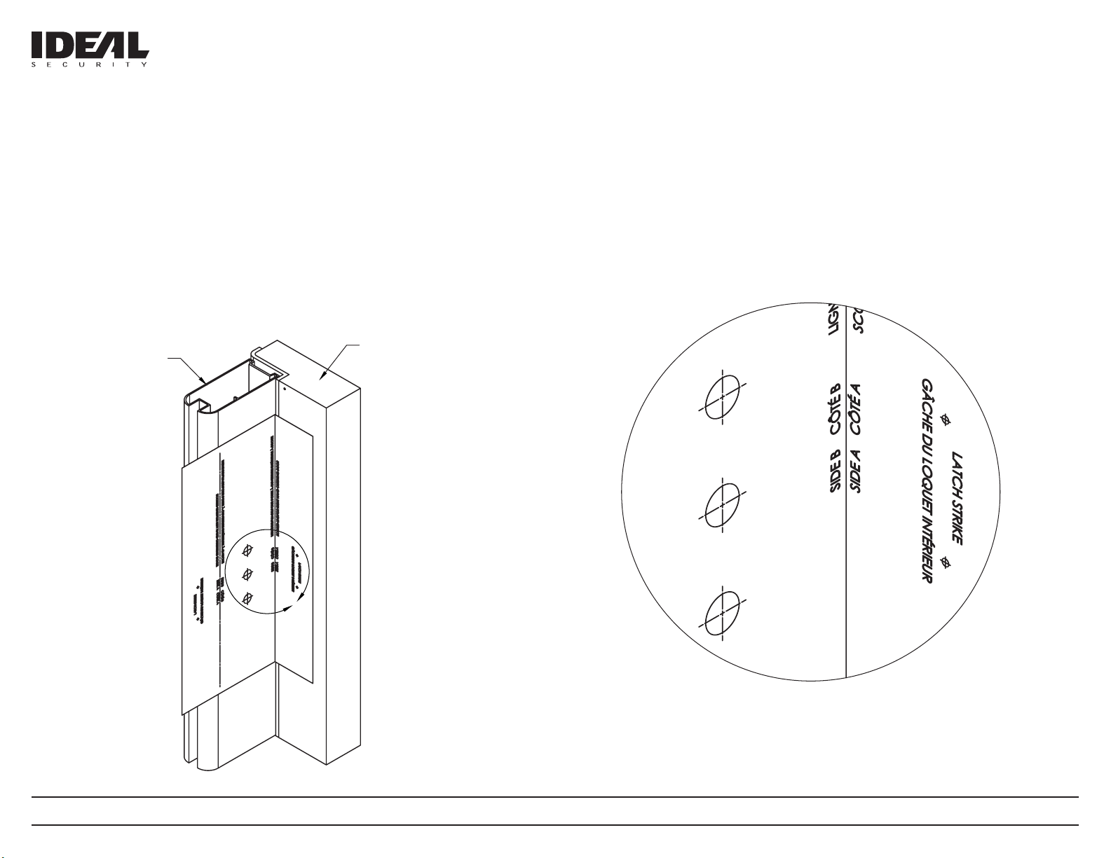
C. TEMPLATE PLACEMENT AND DRILLING INSTRUCTIONS
1. Fold the template on the dotted line to 90° according to the opening of your door - left or right handed.
2. With the door in the closed position, place the folded template on the inside of the door so that the SIDE
A is against the jamb or metal z-bar, which ever projects out furthest; and SIDE B is on the inside surface
of the door.
3. Use a center punch to mark the position of 3 holes on the inside surface of the door on SIDE B. Mark the
position of 2 holes on the jamb on SIDE A (for strikes).
4. Using a 1/16" drill bit, drill pilot holes at all the marked positions.
Drill 3 pilot holes straight through door on SIDE B.
Drill 2 pilot holes to a depth of 1" on SIDE A.
5. Enlarge 3 holes using a 5/16" drill bit straight through door on SIDE B.
JAMB
MONTANT
DOOR
PORTE
A
C. PLACEMENT DE GABARIT ET INSTRUCTIONS DE PERÇAGE
1. Pliez le gabarit sur la ligne pointillée à 90 degrés selon si la porte ouvre à gauche ou à droite.
2. Avec la porte fermée, placez le gabarit plié sur la surface intérieure de la porte pour que le côté A soit
contre le montant ou la barre en Z métallique, selon le plus saillant des deux; et le côté B contre la
surface intérieure de la porte.
3. Utilisez un poinçon pour marquer la position de 3 trous sur le côté B, et la position de 2 trous sur le côté A.
4. Percez des avant-trous sur toutes les locations marquées avec un foret de 1/16 po. Percez 3 avant-trous
à travers la porte complétement sur le côté B. Percez 2 avant-trous de 1 po de profondeur sur le côté A.
5. Agrandir les 3 trous avec un foret de 5/16 po à travers la porte complétement sur le côté B.
Detail A
SCALE 1.5 : 1

www.idealinc.com
RFQGLWV2 – 2022
4/4GLWV2
www.idealinc.com
D. HANDLE & LATCH INSTALLATION
1. Rotate the outside handle to the left or right according to your door handedness.
2. Insert the spindle selected in step B into the center hole of the outside handle from the back side of the
handle housing; ensure the spindle is fully seated into the hole. The spindle locks the handle in place.
3. Place the outside handle assembly on the door. (The spindle should project through inside of the door at
least 1/4" and not more than 3/8". You may need to cut your spindle.)
4. Place the latch on the inside of the door, add a shim if required, and fasten with two machine screws
selected in step B. Do not over tighten screws.
5. Place the latch strike and the thick spacer against the jamb (the spacer is placed in between the strike
and the jamb), align with pilot holes drilled in step C, and fasten with two tapping screws.
Thank you for your purchase. If you require any information
or installation assistance, please contact our customer service.
Nous vous remercions pour votre achat. Si vous avez besoin
d’aide pour l’installation ou information, veuillez communiquer
avec notre service à la clientèle.
Handle Spindle Projected Length
Longueur projectée de la tige de poignée
Max 3/8"
Min 1/4"
D. INSTALLATION DE LA POIGNÉE ET DU LOQUET INTÉRIEUR
1. Tournez la poignée extérieure à gauche ou à droite selon votre porte (gaucher/droitier).
2. Insérez la tige sélectionnée à l’étape B dans le trou central de la poignée extérieure par l’arrière du boîtier
de la poignée; assurez-vous que la tige est bien enfoncée dans le trou. La tige fixe la poignée en place.
3. Placez l’assemblage de la poignée extérieure sur la porte. (La tige devrait projeter à travers l’intérieur de
la porte un max de 3/8 po et min 1/4 po. Vous devrez peut-être couper la tige.)
4. Placez le loquet intérieur sur l’intérieur de la porte, placez une câle d’ épaisseur si néssesaire, fixez avec
deux vis à métaux choisis en étape B. Ne pas trop serrer les vis.
5. Placez la gâche et la cale d’épaisseur contre le montant (la cale est placée entre la gâche et le montant),
alignez-les avec les trous pilotes percés à l’étape C et fixez-les avec deux vis à tôle.
HANDLE
POIGNÉE
DOOR
PORTE
HANDLE SPINDLE
TIGE POUR POIGNÉE
JAMB
MONTANT
LATCH STRIKE SPACER
CÂLE D’ÉPAISSEUR
LATCH STRIKE
GÂCHE POUR LOQUET
LATCH
LOQUET
LATCH SHIM
(if required)
CÂLE D’ÉPAISSEUR POUR LOQUET
(si néssesaire)
Scan code for the most
recent instructions.
Scanner le code pour les
instructions les plus récentes.
Popular Door Lock manuals by other brands


INSYS
INSYS Wittkopp Cawi CombiStar 7250 simplex user manual

Kenwa
Kenwa NHN KT3D-199 quick start guide

Primera
Primera TWIN-TECH 3S-56-732H Fittings guide

Dormakaba
Dormakaba RD10 Installation and operating instructions

SECO-LARM
SECO-LARM E-941D 600Q Series installation manual

AGB
AGB SCIVOLA Assembly instructions