SECO-LARM E-941D 600Q Series User manual

Double-Door Electromagnetic Locks
Installation Manual
E-941DA-1K2Q shown
Model* Holding Force† Material
E-941Dx-600Q 600-lb. (272kg) x2 Anodized aluminum
E-941Dx-1K2Q 1200-lb. (545kg) x2 Anodized aluminum
E-941Dx-600PQ‡ 600-lb. (272kg) x2 Anodized aluminum
E-941Dx-1K2P‡ 1200-lb. (545kg) x2 Anodized aluminum
* "x" is the variable for product color "A" for aluminum, "B" for black, and "D" for dark bronze †Holding force has not been verified by UL
‡With status LED and bond sensor
MOV surge protection
Adjustable mounting bracket
Complete mounting hardware for typical installations
"L" bracket and "Z" brackets available for easy mounting
Detachable faceplate
12/24VDC selectable
NOTES
UL294 Indoor use
The power for the E-941Dx series is to be provided by a Listed (UL294 or UL603) Class 2 power supply.
The E-941Dx series is intended to be used as an access control system accessory, which is installed in
accordance with the manufacturer’s installation and operation instructions, ANSI/NFPA 70 and the local
authority having jurisdiction.
The minimum permissible wire size to be used shall not be less than 22AWG

SECO-LARM Double-Door Electromagnetic Locks
2 SECO-LARM U.S.A., Inc.
Parts List
1x
Mounting plate
2x
Armature plate
4x
Short self
-
tapping screws
2x
Door spacer
1x
Electromagnet
2x
Armature screw
8x
Long self
-
tapping screws
2x
Sexnut bolt
4x
Steel washers
2x
Rubber washer
4x
Hex
-
head mounting screws
4x
Guide pins
4x
Tamper caps
1x
Hex
wrench
1x
Manual
2x
Template
Specifications
Overview
Holding Force 600-lb x2 1,200-lb. x2
Operating voltage 12/24 VDC
Current
draw
12VDC 500mA@12VDC per door (1A total)
24VDC 270mA@24VDC per door (540mA total)
Bond sensor relay 1A@30VDC
Dimensions Magnet 1911/16"x11/16"x15/8" (500x26x40 mm) 21"x15/8"x25/8" (536x42x67 mm)
Armature 71/4"x1/2"x11/2" (185x12x38 mm) 71/4"x5/8"x23/8" (185x16x61 mm)
Operating temperature 32°~120° F (0°~49° C)
Weight 9-lbs. (4kg) 21-lbs. (10kg)
Destructive attack Level I
Line security Level I
Standby power Level I
Endurance Level IV
Long self
-
tapping screws
Electromagnet
Short self
-
tapping screws
Sexnut bolt
Door spacer
Armature screw
Tamper caps
Mounting plate
Hex
-
head
mounting
screws
Rubber washer
Guide pins
Steel washers
Armature
plate

SECO-LARM Double-Door Electromagnetic Locks
SECO-LARM U.S.A., Inc. 3
"L"-
Bracket and
"Z"-Bracket
"L" Bracket Typical Installation
"U" Bracket
Plate Spacers
Armature-Mounting Plate
Installation Applications
When mounting the electromagnets, it may be necessary to use a "Z"-bracket, 1 or 2 "L"-brackets, and/or
plate spacers, depending on the location and the type of doors and frame.
Use the diagram below to help decide whether or not an optional bracket will be necessary for installation.
Installation Notes
1. Read this installation manual thoroughly. A clear understanding of the product and this manual will make
installation much easier.
2. The electromagnetic locks are designed for indoor use ONLY.
3. The most suitable mounting location for the electromagnetic locks may require the use of additional
SECO-LARM accessories such as Z-brackets, L-brackets, and/or spacer plates.
4. Do not run power wires and signal wires in the same conduit as this may cause interference.
5. Do not install a diode in parallel with the electromagnetic locks as this may cause a delay when releasing
the door as well as cause residual magnetism.
6. The best location to install the electromagnetic locks is on the inside of the doors that are being secured
with the wiring concealed in the frame to prevent tampering with the unit.
7. The minimum permissible wire size to be used shall not be less than 22AWG

SECO-LARM Double-Door Electromagnetic Locks
4 SECO-LARM U.S.A., Inc.
Door Frame
Door Door
Door Frame
Door
Template
Door Frame
Ideal
Mounting
Location
Ideal
Mounting
Location
3. Place the template
against the door and
frame. Mark where
the holes are to be
drilled.
2.
Close the doors. Find a mounting location on the
center of the door frame, directly above where
both doors meet when closed.
5. Use a hammer to
lightly tap the guide
pins into the guide pin
holes on the armature
plates.
Drill two 5/16" (8mm) dia. holes through
the armature-plate side of the doors for
the armature screws. Then drill two 5/8"
(16mm) dia. holes for sexnut screws on
the opposite side of the doors.
5/8" (16mm)
5/16" (8mm)
Hollow Metal Door
Reinforced Door
1
/
4
"
(6.8mm) for M8x1.25 thread
Drill two 1/4"
(6.8mm) dia.
and 1" (25mm) deep
hole, tap for M8x1.25
thread on each door.
Solid Core
Drill two 5/16" (8mm) dia. holes on the
doors for the armature screws, and drill
two 1/2" (12.7mm) dia. and 1" (25mm)
deep hole for the sexnut screws.
1
/
2
"
(12.7mm)
5/16" (8mm)
Installation
4. Drill four holes in the frame and six holes in
the door as shown on the template.
1.
Fold the mounting template along the dotted
line to form a 90-degree angle.
6.
Depending on the type of door being protected, drill holes according to the diagrams below:

SECO-LARM Double-Door Electromagnetic Locks
SECO-LARM U.S.A., Inc. 5
Guide pins
TIP: Use a thread-locking compound on the armature
screws to ensure a long-lasting installation.
Armature
screw
8.
Tighten the armature screws
enough so that
the armature plates can withstand a break-in
attempt, but loose enough so that the armature
plates can pivot slightly. Make sure the anti-
spin guide pins are in the two guide pin holes.
Metal
washers
The rubber washer will be
sandwiched between the
two metal washers.
Short
self
-
tapping screws
Mounting Plate
Armature Plate
Long self
-
tapping
screws
7.
Put a rubber washer between the two metal
washers and place them over the armature
screw between the armature plates and the
doors. This allows the plates to pivot around
the screw to compensate for door
misalignment.
9.
Screw the four short self
-
tapping screws through
the mounting plate’s slotted holes, but do not over
-
tighten them. Keeping them loose will allow for adjustment of the plate left or right so that the mounting
plate and the armature plates form a 90-degree angle. See the diagram below.
10.
Once the position of the
mounting plate is
correct, use the eight long self-tapping
screws to permanently mount the
mounting plate.
11.
Drill the cable access holes. Run the power leads
through the cable access holes in the mounting plate
and through the holes in the door frame.

SECO-LARM Double-Door Electromagnetic Locks
6 SECO-LARM U.S.A., Inc.
15.
Connect the power wires according to the wiring
diagram on page 7. Test the unit. Then replace the
front cover and install the hex-head tamper caps (x4).
NOTE: Failure to correctly set the input voltage
may cause damage to the lock.
Position a jumper over
the two middle pins for
24VDC operation
Position two jumpers
on all four pins for
12VDC operation
Voltage Selection Jumpers
CAUTION: The two electromagnets each have their
own voltage selection jumpers.
Maximum Distance from Power Source to Electromagnetic Lock
For a complete chart, please visit www.seco-larm.com
12VDC Minimum Wire Gauge
24VDC Minimum Wire Gauge
Wire Length 25ft.
50ft. 75ft. 100ft.
150ft.
200ft.
250ft.
300ft.
400ft.
500ft.
1000ft.
Wire Gauge@500mA 20 18 18 18 16 14 14 12 10 -- --
Wire Length
25ft. 50ft. 75ft. 100ft.
150ft.
200ft.
250ft.
300ft.
400ft.
500ft.
1000ft.
Wire Gauge@250mA
22 22 22 20 18 18 16 16 14 14 14
14.
Cut the wires so they are long enough to
connect with the terminal block. Set the
voltage using the selection jumpers
based on your input voltage.
12.
Remove the cover from the front of the
electromagnets. Run the power leads
through the large cable access holes.
13.
Push the electromagnet against the mounting plate so
the ends are flush with each other. Use the Hex
wrench to screw the hex-head mounting screws
through the bottom of the electromagnets into the
mounting plate.
NOTE: THIS SHOULD BE THE VERY LAST STEP, AS ONCE
THE TAMPER CAPS ARE IN PLACE THEY ARE
VERY DIFFICULT TO REMOVE.

SECO-LARM Double-Door Electromagnetic Locks
SECO-LARM U.S.A., Inc. 7
Wiring Diagram
NOTES
Connect switching devices like push-to-exit switches between the power source and the positive
terminal of the lock. Connecting them to the negative terminal may cause a delay in unlocking.
Wiring Diagram
*A fail-safe lock unlocks when power is lost so that, in case of an emergency such as a fire in the building, the fail-safe lock will automatically
unlock allowing personnel to escape quickly.
NOTE: All field wiring must be within the protected area.
Control Device
+
–
Power Supply
12/24 VDC
N.C.
COM
N.O.
–
+
= 12VDC
= 24VDC
Voltage
jumpers
Circuit Board
Maglock
(Fail
-
safe)* (Indoor)
Key Switch
(Outdoor)
N/C Exit Button
(Indoor)
Keypad
(Outdoor)
Access Control
Unit

SECO-LARM Double-Door Electromagnetic Locks
Troubleshooting
Doors lock, but can easily
be forced open
Make sure the electromagnet and armature plates are properly
aligned.
Make sure the contact surfaces of the electromagnet and armature
plates are clean and free from rust.
Check the power leads with a meter, and make sure 12VDC or
24VDC is present.
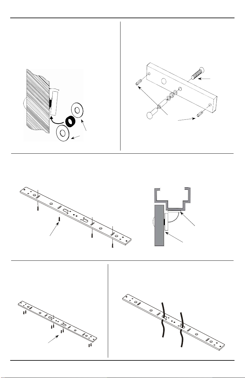
Make sure the rubber washer is installed and free from damage.
Delay in door releasing
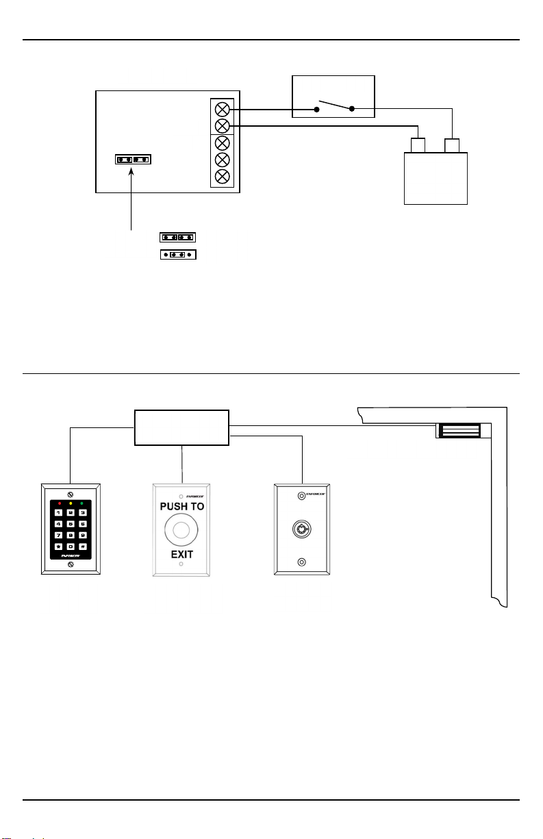
The electromagnet is fitted with a metal oxide varistor to prevent
interference, so do not install a second diode.
Ensure that the control device is connected between the power
source and the positive terminal of the lock
SECO-LARM ® U.S.A., Inc.
16842 Millikan A
venue, Irvine, CA 92606
Website: www.seco
-
larm.com
Phone: (949) 261-2999 | (800) 662-0800 E-mail: sales
@
seco-larm.com
NOTICE: The SECO-LARM policy is one of continual development and improvement. For that reason, SECO-
LARM reserves
the right to change specifications without notice. SECO-
LARM is also not responsible for misprints. All trademarks are the
property of SECO-LARM U.S.A., Inc. or their respective owners. Copyright © 2022 SECO-LARM U.S.A.,
Inc. All rights
reserved.
California Proposition 65 Warning:
These products may contain chemicals which are known to the State of California to
cause cancer and birth defects or other reproductive harm. For more information, go to www.P65Warnings.ca.gov.
IMPORTANT:
Users and installers of this product are responsible for ensuring that the installation and configuration of this
product complies with all national, state, and local laws and codes. SECO-
LARM will not be held responsible for the use of
this product in violation of any current laws or codes.
IMPORTANT WARNING:
Incorrect mounting which leads to exposure to rain or moisture inside the enclosure could cause
a dangerous electric shock, damage the device, and void the warranty. Users and installers are resp
onsible for ensuring that
this product is properly installed and sealed.
PITGW1
MI_E
-
941Dx
-
xxxQ_220513.docx
LIMITED LIFETIME WARRANTY: This SECO-
LARM product is warranted against defects in material and workmanship
while used in normal service for the lifetime of the product. SECO-
LARM’s obligation is limited to the repair or replacement
of any defective part if the unit is returned, transportation prepaid, to SECO-
LARM. This Warranty is void if damage is caused
by or attributed to acts of God, physical or electrical misuse or abuse, neglect, repair or alteration, improper or abnormal
usage, or faulty installation, or if for any other reason SECO-
LARM determines that such equipment is not operating properly
as a result of causes other than defects in material and workmanship. The sole obligation of SECO-
LARM and the purchaser’s
exclusive remedy, shall be limited to the replacement or repair only, at SECO-LARM’s option. In no event shall SECO-
LARM
be liable for any special, collateral, incidental, or consequential personal or property damage of any kind to the purchaser
or
anyone else. For all other countries, the warranty is 1 (one) year.
This manual suits for next models
8
Table of contents
Other SECO-LARM Door Lock manuals

SECO-LARM
SECO-LARM SD-997SMB-AQ User manual

SECO-LARM
SECO-LARM SD-997BQ User manual

SECO-LARM
SECO-LARM SD-998C-D3Q User manual

SECO-LARM
SECO-LARM Enforcer SD-994C User manual

SECO-LARM
SECO-LARM SD-995C-LE25 User manual

SECO-LARM
SECO-LARM SLI SD-997B-1SQ User manual

SECO-LARM
SECO-LARM Enforcer SD-997A User manual

SECO-LARM
SECO-LARM SD-993C-D3Q User manual

SECO-LARM
SECO-LARM SD-996C-U1VQ User manual

SECO-LARM
SECO-LARM SD-997B-GBQ User manual