IDEAL FAST-WAY Si-Low 210 A1 User manual

Si-Low 210-A1
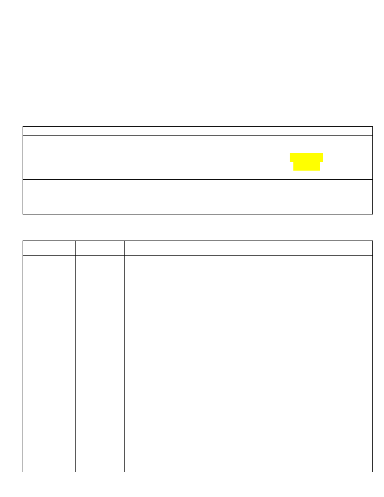
TABLE OF CONTENTS
DESCRIPTION PAGE #
Fast-Way Limited Warranty Policy
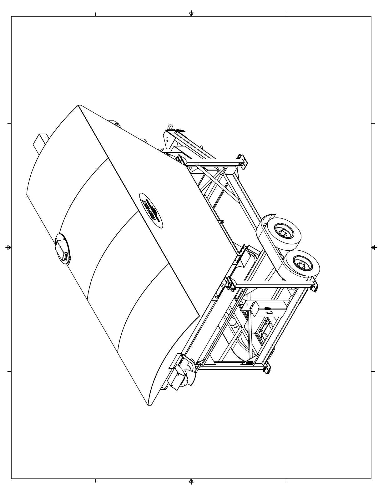
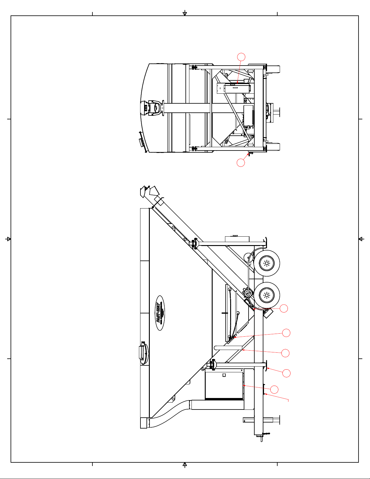
Si-Low 210 A1 Over View
Electrical Control Panel 440/460 volt 3 phase 2
Electrical Control Panel 240 volt 3 phase 3
Main Component List 4
General Layout 5
Preparing Silo for Transport 6
Set Up Procedure 7
Safety Rules 8
Sumitomo Gear Box Lubrication 9
Operating Procedure 10, 11
Auger Speed Reducer & Electric Driven Motor 12, 13
Auger Drive Assembly with Guard 14, 15
Auger to Slide Gate to Silo 16, 17
Upper Bearing Assembly 18
Optional Control System 19
Bag-house Assembly 20,21
Maintenance of Bag-house 22
Adjustable Legs & Load Cells 23
Silo Trailer Wheel Components 24
Vibrator & Aeration System 25
Vibrator & Optional Pulse Aeration Wiring 26
Man Hole 27
Electrical Connector for Towing 28
12Volt DC Wiring 29
Slide Gate Assembly 30, 31
Electrical Control Panel 440/460 volt 3 phase with Remote 32
Electrical Control Panel 240 volt 3 phase with Remote 33
Load Cell J Box wiring diagram 34
Fuel Tank 35
Cardinal Scale Manual
Cyclo Gear Box Manual

FAST-WAY LIMITED WARRANTY POLICY
Ideal Manufacturing, Inc., hereinafter referred to as “Manufacturer” warrants FAST-WAY
equipment to be free from defect in material and workmanship, under normal use and service,
for a period of one (1) year from the date of original purchase. Manufacturer will, at its
option, replace or repair at factory in Billings, MT, any part or parts which shall appear, to
the satisfaction of the Manufacturer, upon inspection at its factory, to have been defective in
material or workmanship. This warranty does not obligate the Manufacturer to bear any
transportation charges in connection with replacement or repair of defective parts. This
warranty excludes electrical components and damage due to Acts of God, unauthorized
modifications, misuse, abuse or negligence to this product.
In order to proceed with a warranty claim, Ideal Manufacturing must be notified of the
problem. A new part will be shipped out prepaid (Ground UPS). If the customer requests
that the part be expedited that shipping charge will be charged to the owner.
The part that is being warranted must be returned to Ideal Manufacturing postage prepaid.
When the new part is shipped out, it will go out with an invoice and a warranty part return
number. The defective part must be returned to Ideal Manufacturing, Inc freight prepaid, with
the warranty part return number. At that time the invoice will be considered paid in full.
This warranty is exclusive and in lieu of all other obligation, liabilities or warranties. In no
event shall Ideal Manufacturing be liable or responsible for incidental or consequential
damage or for any other direct or indirect damage loss, cost, expense or fee.
This warranty shall not apply to any products or parts that have been altered or repaired
without written consent of Ideal Manufacturing.
Labor to remove and reinstall defective product or parts will be paid from a labor rate and
schedule only. Consult Ideal Manufacturing for that rate and schedule.
For further information on returning your product or questions concerning Ideal
Manufacturing warranty, please contact Ideal Manufacturing.
Ideal Manufacturing Inc., 2011 Harnish Blvd., Billing’s, Montana 59101, 1-800-523-3888 toll free, 1-406-656-4360 phone, 1-406-656-4363 fax
1
1
2
2
3
3
4
4
A A
B B
C C
D D
Si-Low 210 A1
1
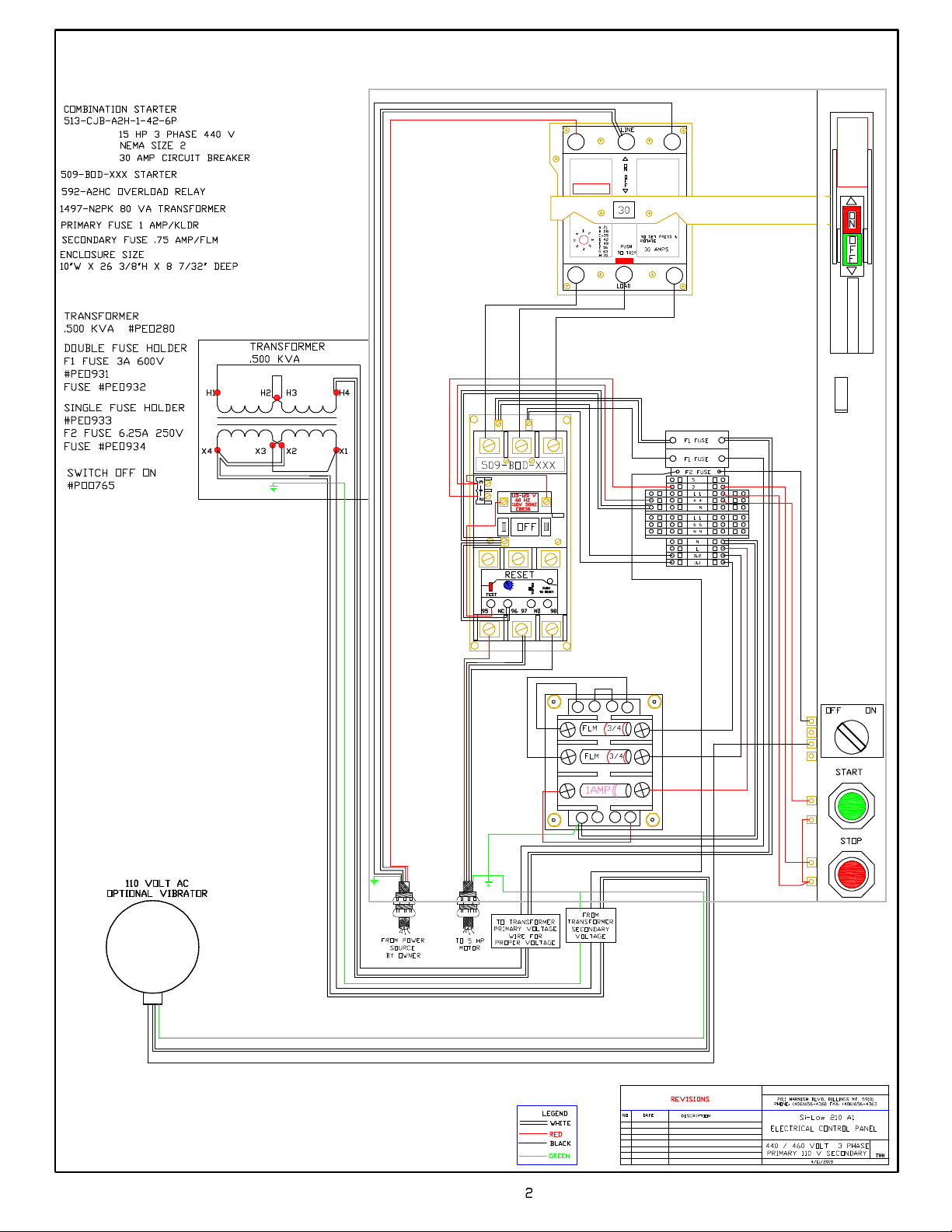
IDEAL MANUFACTURING INC.
440 / 460 VOLT THREE PHASE

IDEAL MANUFACTURING INC.
240 VOLT THREE PHASE

4
Si-Low 210 A1
MAIN COMPONENT LIST
REF# DESCRIPTION
1 Auger to Silo Slide Gate
2 Speed Reducer and Electric Motor
3 Electrical Box
4 Aeration System
5 Fill Pipe
6 Bag Type Dust Collector and Clean Out Hopper
7 Side-Wind Tongue Jack
8 Adjustable Leg Assembly
9 Auger Drive Assembly
10 Man Hole
11 Upper Bearing Assembly
12 Vent Hose
13 Red Side Marker
14 Red Brake Light
15 Amber Side Marker
16 Tire and Axle Assembly
17 Cement Silo 200 Barrel capacity (30 tons)
18 Auger
19 Main Frame
20 Hand Crank for Slide Gate

1
1
2
2
3
3
4
4
A A
B B
C C
D D
Si-Low 210 A1
General Lay Out
Ideal Mfg., Inc. SL210 A1-213
5
7
6
15
10
54
8
18
17
3
129
14
14
20
16
19
13
11
12
9
8
10

6
Si-Low 210-A1
PREPARING SILO FOR TRANSPORT
1. Most important is to be positive that all cement has been removed from silo, auger
and bag-house.
2. Using a rubber mallet, hit the sidewalls of hopper section of silo; listening for a
hollow sound. Clean out remaining cement. A bag of floor dry will aid in cleaning
out the auger by opening the manhole on top of the silo, pour the floor dry inside of
the cement silo. Turn auger on, open discharge gate. Run auger until the floor dry
no longer comes out of discharge end of auger. Turn auger off and close discharge
gate.
3. Disconnect air supply.
4. Disconnect electrical supply. CAUTION! Only a qualified person should do this.
5. Using side-wind tongue jack, raise front of cement silo until all weight is off both
front legs...
6. Remove keepers from both front leg pins, slowly remover leg pins. CAUTION! Inner
leg will fall to ground. STAY CLEAR WHEN REMOVING LEG PINS.
7. Using handle on leg pad, raise leg until pin can be installed in first hole. Install leg
pin through hole, install keeper. Repeat on second leg at front of cement silo.
8. Using side-wind tongue jack, lower front of cement silo until all weight is on both
rear legs.
9. Remove keepers from both leg pins; slowly remove leg pins. CAUTION! Inner leg
will fall to ground. STAY CLEAR WHEN REMOVING LEG PINS!
10. Using handle on leg pad, raise leg until leg pin can be installed in first hole. Install
leg pin through hole and install keeper. Repeat on second leg at rear of cement silo.
11. Using side-wind tongue jack, raise front of cement silo until tow vehicle can back
under pintle hitch.
12. Back tow vehicle under pintle hitch, using top-wind tongue jack, lower front of
cement silo onto tow vehicle hitch, secure latch. Hook safety chains and break-away
cable to tow vehicle. Plug in lights, check lights for proper operation.
13. Raise top-wind jack to full up position. See drawing (Adjustable Legs) on page 23.
14. Clean all debris of silo before towing.

7
Si-Low 210-A1
SET UP PROCEDURE
1. Select a level site with solid footing for setting up and operating cement silo.
2. Block tires, to keep cement silo from moving, before unhooking tow vehicle..
3. Unhook tow vehicle, move vehicle away from cement silo.
4. Remove keepers from both leg pins at rear of cement silo. Slowly remove leg
pins. CAUTION! Inner leg will fall to ground; STAY CLEAR WHEN
REMOVING LEG PINS! See page 23.
5. Using side-wind tongue jack, lower front end of silo until leg pins can be
installed in second hole in rear legs.
6. Install leg pins through holes in both rear legs; install keepers.
7. Remove keepers from both leg pins, at front of silo. Slowly remove leg pins
CAUTION! Inner leg will fall to ground. STAY CLEAR WHEN
REMOVING LEG PINS!
8. Using sdie-wind tongue jack, raise front of cement silo until leg pins can be
installed in second hole in front legs
9. Install leg pins through holes in both front legs; install keepers.
10. Using sdie-wind jack, lower front of cement silo until all weight is off jack.
11. Check cement silo for level and stability. Correct as needed..
12. Connect electric power to disconnect box at rear of cement silo, using
qualified person See page 2 and 3 for diagram. Check for proper rotation of
Auger. Correct as needed.
13. Connect air supply to valve. Silo fluidizer aerators require 10.2 CFM @ 90
PSI with a 60 gallon tank. See drawing #110 on page 25.

8
SAFETY RULES
Follow instructions. Don’t take chances. If you don’t know, ask. When setting up
lowering or putting equipment into traveling position, follow all instructions in operator’s
manual.
Correct or report unsafe conditions. If you are not sure of how to correct a hazard, report
it and get help.
Help keep everything clean and orderly. Trips or falls can cause serious injuries.
Use the right tools and equipment for the job. Use them safely. Replace all machine
guards after repairs.
Report all injuries and get first aid or medical treatment promptly.
Use, adjust and repair equipment only when authorized.
Use prescribed protective equipment. Keep it in good condition. Wear your hard hat,
safety climbing devices or belt. Wear safe clothing to protect you from material being
handled, cold or hot. Wear dust mask when conditions require them. Gloves, safety
glasses or eye protection, and ear plugs for noise.
Don’t horseplay; avoid distracting others.
When lifting, bend your knees and get help for heavy loads.
Don’t repair or adjust equipment while in motion. Shut off power at source, gasoline
engines or electric motors.
Gasoline, L.P. gases fumes are highly explosive.
CYCLO BEVEL BUDDYBOX LUBRICATION
NOTES: Total amount of oil needed is 0.4 gallons. Output section use 0.44 gallons.
Input section use 0.22 gallons. Omala Oil 100, 150 installed at factory.
1. Cyclo input section on small units is greased packed from the factory and is
maintenance free for 20,000 operating hours
2. Cyclo vertical section of units is grease packed and requires periodic
replenishment.
3. Consult factory if greased lubrication of gear output section is required.
4. Before reinstalling plugs, reapply Teflon tape to threads to prevent leakage.
5. “G” denotes grease lubricated as standard.
Standard Oils
Ambient Temperature (ºF)
ChevronTexaco Exxon Oil Mobil Oil Shell Oil BP Oil
14 to 41º
EP Gear Spartan EP Mobilgear 626 Omala Oil Energol
Compound 68 68 (ISO) VG 68) 68 GR-XP 68
32 to 95º
EP Gear Spartan Mobilgear Omala Oil GR-XP 100
Compound EP 100 627, 629 100, 150 GR-XP 150
100, 150 EP 150 (ISO) VG 100, 150)
86 to 122º
EP Gear Spartan Mobilgear Omala Oil Energol
Compound EP 220 630, 632 220, 320 GR-XP 220
220, 320, 460 EP 320 633, 634 460 GR-XP 320
EP 460 (ISO VG 220-460) GR-XP 460
Oil Fill Quantities Unit U.S. Gallons *G = Grease
Frame Size Y1
Output Input
Y2
Output Input
Y3
Output Input
Y4
Output Input
Y5
Output Input
Y6
Output Input
2A100, 2A105
2A110, 2A115
2A120, 2A125
2A140, 2A145
2B120, 2B125
2B140, 2B145
2B160, 2B165
2C140, 2C145
2C160, 2C165
2C170, 2C175
2D160, 2D165
2D170, 2D175
2E170, 2E175
G
G
0.29
G
0.08
G
0.48 0.12
0.20
0.12
0.87 0.20
0.28
0.18
1.16
0.24
1.95 0.24
G
G
0.26
G
G
G
0.37 G
G
G
0.92 G
G
G
1.32
G
1.93 G
G
G
0.29
G
0.08
G
0.48 0.12
0.20
0.12
0.87 0.20
0.28
0.18
1.16
0.24
1.95 0.24
G
G
0.26
G
G
G
0.48 G
G
G
1.16 G
G
G
1.11
G
1.59 G
G
G
0.45
G
0.08
G
0.61 0.12
0.20
0.12
0.95 0.20
0.28
0.18
1.48
0.24
1.90 0.24
G
G
0.42
G
0.08
G
0.66 0.12
0.20
0.12
1.4 0.20
0.28
0.18
1.59
0.24
2.80 0.24
9

10
Si-Low 210-A1
OPERATING PROCEDURE
A. CHARGING SILO
1. Close silo discharge gate, (REF# 1)
2. Air pump cement through filler pipe, (REF# 5))
3. You must open ball valve on side of bag-house to operate vibrator to clean
filter bags each time after filling silo. (REF #6). Vibrator requires 4.5
CFM @ 60 PSI or 5.5 CFM @ 80 PSI. Or open side doors and manualy
shake bags.
4. Open cleanout gate, at bottom of bag-house hopper, remove over flow
cement from hopper; close gate. (REF #6)
B. AUGER OPERATION
1. Raise disconnect handle on electrical panel to ON position. (REF #3).
2. Open discharge gate. (REF#1)
3. Turn air supply on. (Supplied by customer)
4. Open ball valve on aerator system for one minute.(REF# 4) Close ball
valve. If optional pulse system is purchased turn air valve control to ON
position. (REF# 3). (Optional)
5. Push start button, (REF # 3). Auger will start. Turn vibrator on. Optional
aerators will pulse on for three seconds, off for seven seconds, until stop
button is pushed.
NOTE: If slower delivery of cement is needed; close discharge gate to
get desired amount.
6. Fill unit with cement.
7. When unit is filled push stop button, and turn vibrator off. (REF #3)
8. Close discharge gate. (REF # 1).
9. Lower disconnect handle on electrical panel to OFF position. (REF #3).
10. NOTE: The auger should be emptied on last load of the shift. Discharge
boot should be rolled up and secured to keep moisture out of auger tube to
prevent build up on auger screw.
1
1
2
2
3
3
4
4
A A
B B
C C
D D
Si-Low 210 A1
Operating Procedure
Ideal Mfg., Inc. SL210 A1-213-1
11
6
54
3
1
1
8
BAGHOUSE CLEAN
OUT GATE

12
Si-Low 210-A 1
AUGER DRIVE COMPONENTS
SL210 A1-201
REF NO.
PART NO.
DESCRIPTION
REQ’D
1
SLO301
Auger Assembly
N/A
2
POO677
Electric Motor
1
2
-
A
POO637
Diesel Engine
1
2
-
B
POO638
Gas Engine
1
3
POO676
Speed Reducer
1
4
POO679
2TB66 Sheave
1
4
-
A
POO63
6
Pulley Clutch (Diesel & Gas Engine)
1
5
POO681
P 1 5/8 Bushing
1
6
POO138
2BK47H Sheave (Electric Motor)
1
6
-
A
POO649
2BK60H Sheave (Diesel Engine)
1
6
-
B
POO233
2BK70H Sheave (Gas Engine)
1
7
POO680
H 7/8 Bushing
1
8
SLO310
Drive Mounting Frame
1
9
SLO311
Silo Frame
N/A
10
N/A
1/2
-
13 x 18 All Thread
2
11
N/A
1/2
-
13 Hex Nut
16
12
NA
1/2 Lock washer
12
13
NA
1/2 USS Flat washer
1
6
14
NA
1/2
-
13 x 2” Hex Bolt
4
15
NA
1/2
-
13 x 2 1/2
” Hex Bolt
4
16
NA
3/8
-
16 x 1” Hex Bolt
8
17
NA
3/8 Lock Was
her
8
18
NA
3/8
-
16 Hex Nut
8
19
NA
3/8 USS Flat Washer
8
20
NA
M 12 Flat Washer (speed reducer not shown)
4
21
NA
M 12 Lock Washer (speed reducer not shown)
4
22
NA
M 12
-
1.75 X 25 MM Bolt (speed reducer not shown)
4
23
NA
¼
-
20 x ¾ Hex Bolt
8
24
NA
¼
Lock Washer
8
25
NA
¼
-
20 Hex Nut
8
26
SLO312
Belt Guard Back
1
27
SLO313
Belt Guard Cover
1
28
N/A
3/16 x 3/16 x 1 3/8 Key Stock
1
29
N/A
3/8 x 3/8 x 2 3/4 Key Stock
1
30
POO767
B
-
96 V Belt
2
31
SLO314
Guard Mount Front
1
32
SLO315
Guard Mount Rea
r
1

1
1
2
2
3
3
4
4
A A
B B
C C
D D
SHEET 1 OF 1
DRAWN
CHECKED
QA
MFG
APPROVED
T Henry 4/9/2019
DWG NO
SL210 A1-201
TITLE
Si-Low 210 A1
SIZE
C
SCALE
Ideal Mfg., Inc.
REV
2011 Harnish Blvd. Billings MT 59101 Tel. (406) 656-4360
WEIGHT
PROJECTION
REMOVE ALL BURRS
UNLESS OTHERWISE SPECIFIED
DIMENSIONS ARE IN INCHES
TOLERANCES ARE:
.XX ± .01
.XXX ± .005
FRACTIONS ± 132
ANGLES ± 1°
DRILLED HOLE ± 164
13
11
13
11
12
13
11
10
15
8
14
2
29
2-A / 2-B
4-A
27
23
26
24
25
31
7
30
6 / 6-A / 6-B
4
5
16
18
17
19
32
16
18
17
11
12
13
13
12
11
11
12
13
16
19
17 18
23
24
25
11
12
13
AUGER DRIVE COMPONENTS
13

14
Si-Low 210-A1
LOWER AUGER ASSEMBLY
SL210 A1-212
REF NO.
PART NO. DESCRIPTION REQ’D
1 SLO301 Auger Assembly N/A
2 SLO343 Lower Auger Shaft 1
3 POO676 Speed Reducer 1
3A POO795 Bushing 1
4 N/A 5/8-11 x 4 Hex Bolt (not shown) 2
5 N/A 5/8-11 Lock Nut (not shown) 2
6 SLO344 Auger Drive Shaft 1
7 SLO342 Auger Flighting 1
8 POO791 Pillow Block Bearing 1
9 SLO345 Auger Flange Drive End 1
10 POO689 Felt Seal 6 x 6 1
11 SLO346 Felt Seal Plate 1
12 POO790 Flange Block Bearing 1
13 SLO306 Chain Guard Back 1
14 SLO307 Chain Guard Cover 1
15 POO793 Drive Sprocket 2
16 POO688A Off Set Link (not shown) 1 (if needed)
17 POO688 Roller Chain (not shown) 1
18 POO688B Master Link (not shown) 1
19 SLO308 1/2 x 1/2 x 2 1/4” Key Stock 2
20 N/A 3/8-16 x 1” Hex Bolt 6
21 N/A 3/8” Lock Washer 6
22 N/A 3/8” Hex Nut 6
23 N/A 1/2 USS Flat Washer 32
24 N/A 1/2 Lock Washer 4
25 N/A 1/2-13 Hex Nut 4
26 N/A 1/4-20 x 1” Hex Bolt 6
27 N/A 1/4” Lock Washer 6
28 N/A 1/4-20 Hex Nut 6
29 N/A 1/2-13 x 3” Hex Bolt 2
30 N/A 1/2 SAE Flat Washer 2
31 N/A 1/2 Lock Washer 2
32 N/A 1/2-13 Hex Nut 2
33 N/A M 12-1.75 X 25 MM 4
34 N/A M 12 Lock Washer 4
35 N/A M 12 Flat Washer 4

1
1
2
2
3
3
4
4
A A
B B
C C
D D
SHEET 1 OF 1
DRAWN
CHECKED
QA
MFG
APPROVED
T Henry 4/9/2019
DWG NO
SL210 A1-212
TITLE
Si-Low 210 A1
SIZE
C
SCALE
Ideal Mfg., Inc.
REV
2011 Harnish Blvd. Billings MT 59101 Tel. (406) 656-4360
WEIGHT
PROJECTION
REMOVE ALL BURRS
UNLESS OTHERWISE SPECIFIED
DIMENSIONS ARE IN INCHES
TOLERANCES ARE:
.XX ± .01
.XXX ± .005
FRACTIONS ± 132
ANGLES ± 1°
DRILLED HOLE ± 164
27
28
14
19
15
26
13
25
24
12
23
11
10
23
22
21
9
25
4
20
1
6
30
31 32
8
29
35
34
33
3
3-A
7
LOWER AUGER ASSEMBLY
15

16
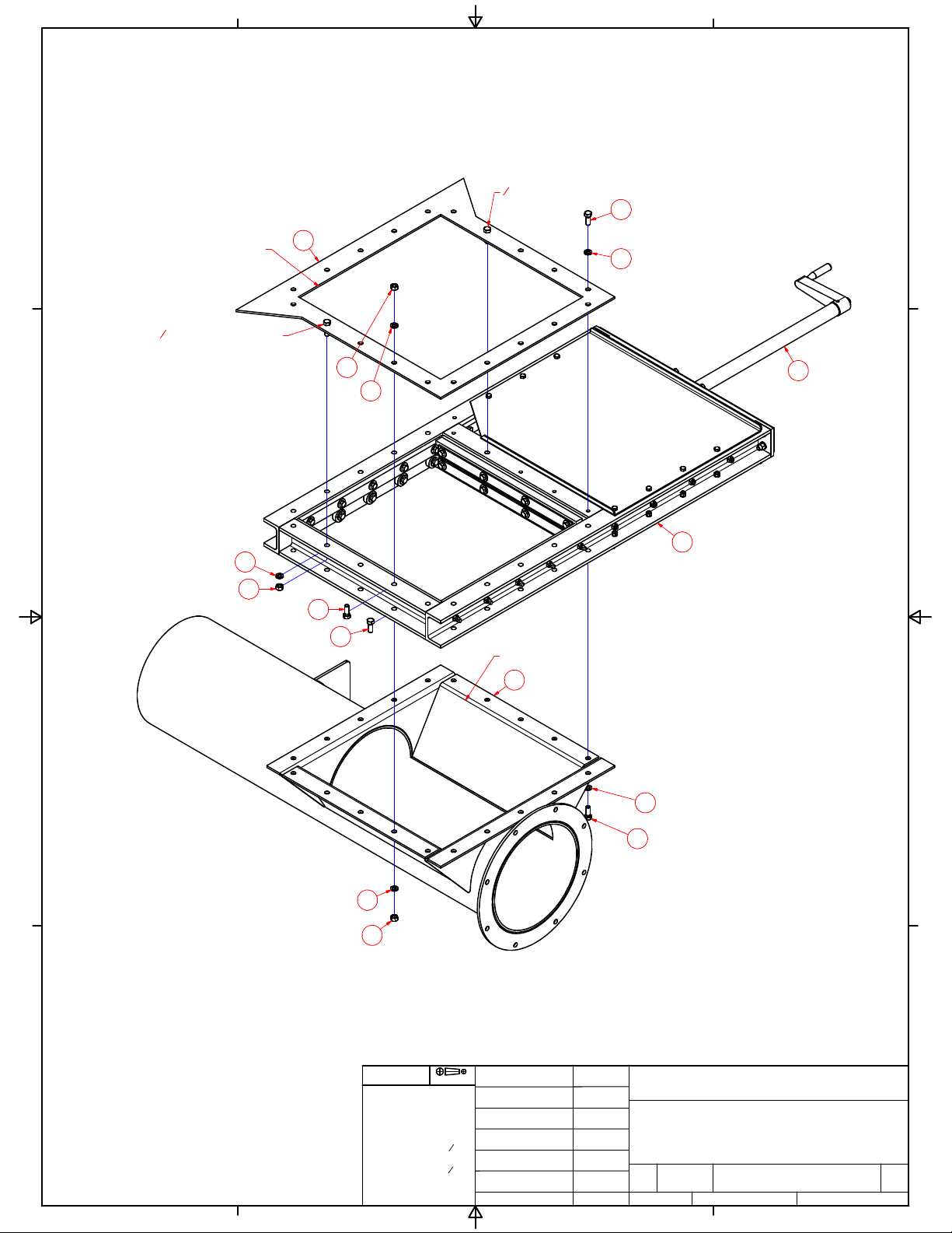
Si-Low 210-A1
AUGER TO SLIDE GATE TO SILO
SL210 A1-202
REF NO. PART NO. DESCRIPTION REQ’D
1 SLO318 Silo (flange) 1
2 POO783 I Slide Gate 1
3 SLO301 Auger Assembly 1
4 F00173A Gate Handle Extension 1
5 N/A 3/8-16 x 1 1/4 Hex Bolt 29
6 N/A 3/8 Lock Washer 40
7 N/A 3/8-16 Hex Nut 31
8 N/A 3/8-16 X 1 Hex Bolt 9
1
1
2
2
3
3
4
4
A A
B B
C C
D D
SHEET 1 OF 1
DRAWN
CHECKED
QA
MFG
APPROVED
T Henry 4/9/2019
DWG NO
SL210 A1-202
TITLE
Si-Low 210 A1
SIZE
C
SCALE
Ideal Mfg., Inc.
REV
2011 Harnish Blvd. Billings MT 59101 Tel. (406) 656-4360
241.8 lbmass
WEIGHT
PROJECTION
REMOVE ALL BURRS
UNLESS OTHERWISE SPECIFIED
DIMENSIONS ARE IN INCHES
TOLERANCES ARE:
.XX ± .01
.XXX ± .005
FRACTIONS ± 132
ANGLES ± 1°
DRILLED HOLE ± 164
AUGER INLET
HOPPER OUTLET
38BOLT WELDED TO FLANGE
38BOLT WELDED TO FLANGE
8
6
4
2
7
6
6
7
5
5
7
6
AUGER TO SLIDE GATE TO SILO
17
6
8
1
3
1
1
2
2
3
3
4
4
A A
B B
C C
D D
SHEET 1 OF 1
DRAWN
CHECKED
QA
MFG
APPROVED
T Henry 4/9/2019
DWG NO
SL210 A1-207
TITLE
Si-Low 210 A1
SIZE
C
SCALE
Ideal Mfg., Inc.
REV
2011 Harnish Blvd. Billings MT 59101 Tel. (406) 656-4360
N/A
WEIGHT
PROJECTION
REMOVE ALL BURRS
UNLESS OTHERWISE SPECIFIED
DIMENSIONS ARE IN INCHES
TOLERANCES ARE:
.XX ± .01
.XXX ± .005
FRACTIONS ± 132
ANGLES ± 1°
DRILLED HOLE ± 164
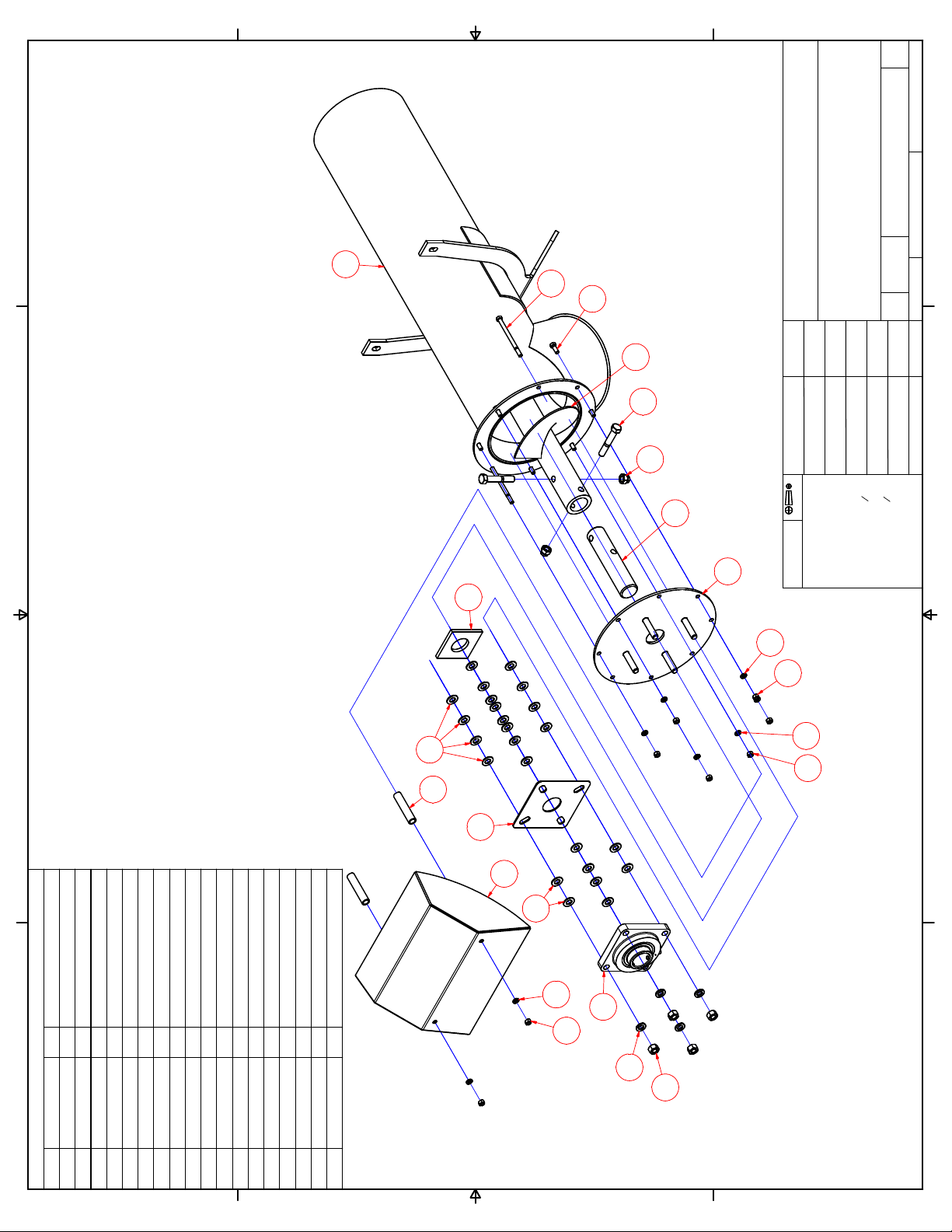
PARTS LIST
DESCRIPTIONQTYPART NUMBERITEM
3/8-16 X 1 HEX BOLT6N/A1
3/8-16 HEX NUT8N/A2
3/8 LOCK WASHER8N/A3
3/8-16 X 5 1/2 HEX BOLT
2
N/A
4
5/8 USS FLAT WASHER24N/A
5
5/8-11 HEX NUT4N/A6
5/8 LOCK WASHER4N/A7
5/8-11 X 4 HEX BOLT2N/A8
5/8-11 NYLOCK HEX NUT2N/A9
UPPER AUGER SHAFT1F0017410
FELT SEAL
1
POO689
11
FLANGE BLOCK BEARING1POO79212
AUGER ASSEMBLY1SLO30113
AUGER FLIGHT ASSEMBLY1SLO34214
FELT SEAL PLATE1SLO34615
UPPER AUGER FLANGE
1
SLO34716
RAIN CAP
1
SLO350-1
17
SPACER2SLO351-118 13
4
1
8
9
10
16
3
23
6
7
12
5
15
5
11
23
17
18
14
UPPER AUGER ASSEMBLY
18
2
Table of contents
Other IDEAL Industrial Equipment manuals


