Delixi NAVIGATOR Series User manual

CDC19s Series
Switching capacitor contactors
NAVIGATOR
Series
User Manual
Please carefully read this User Manual before installing
and operating the product, and keep this manual properly
for future reference

CDC19s Series Switching Capacitor Contactor
Safety Notice
Please carefully read this instruction before the installation, operation, run, maintenance, and inspection,
and follow the contents of the instruction to properly install and operate this product.
Danger:
●Do not operate the contactor with your wet hands;
●Do not touch the energized parts during operation;
●Mark sure that the product is deenergized during the maintenance and service;
Caution:
●The installation, maintenance and service shall be performed by the qualified professional;
●Please confirm that the product voltage, current, frequency and usage category meet the requirements before
use;
●Please turn on teh control loop for no-load operation test, and then power on the load after no any
abnormality is found during test;
●Please tighten the terminal blocks regularly and remove the deposited dust;
●Do not allow foreign objects fall into the product:
●Not used for jogging;
●To purchase accessories, please select the matching accessories provided by our company;
●If found any damage or abnormal sound when unpacking, please refuse to use it and contact the supplier;
●When scrapping the product, please dispose the product waste properly. Thanks for your cooperation.
About CDC19s Series Product
●Panel Introduction
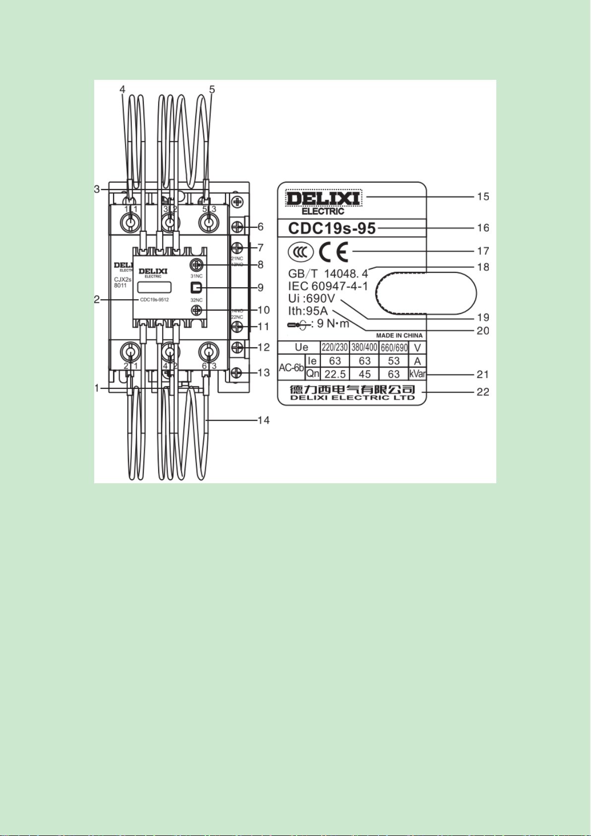
Fig. 1 Product Diagram
Legends:
1 - Main circuit outlet terminal 2/T1, 4/T2, 6/T32
2 - Product model
3 - Main circuit inlet terminal 1/L1, 3/L2, 5/L3
4 - Coil inlet terminal A1 5 –Coil outlet terminal A2
6 –Normally-closed auxiliary inlet terminal 21NC 7 –Normally-open auxiliary inlet terminal 13NO
Remove this label before
installing accessories
The installation dimensions are same
with those of CDC9

8 –Normally-closed auxiliary inlet terminal 31NC 9 –Pre-charged contact set
10 - Normally-open auxiliary outlet terminal 32NC 11 - Normally-open auxiliary outlet terminal 14NO
12 –Normally-closed auxiliary outlet terminal NC 22 13 –Coil outlet terminal A2
14 - Current limiting reactor 15 –Company logo
16 - Product model 17 –Certification mark
18 –Standards: GB/T 14048.4, IEC 60947-4-1
19 - Insulation voltage Ui
20 –Ith: Resistive free air current
21 - Ue, Ie, and controllable capacitor capacity under the usage category
22- Company name
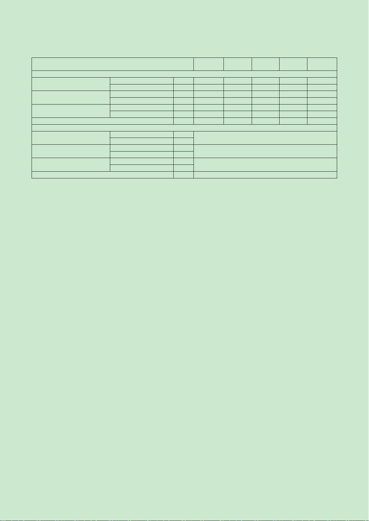
●Technical Parameters
Main circuit Table 1 Technical parameters of main circuit
Product model
Rated
insulation
voltage Ui V
Rated
operating
current Ie A
Rated operating
voltage Ue A
Resistive free
air current Ith A
Controllable capacity
Inrush current
suppression
capacity
220/230V
380/400V
660/690V
Rated capacity QnkVar
CDC19s-25
690
17
220/230V
380/400V
660/690V
25
6
12
18
35Ie
CDC19s-32
24
32
9
18
26
CDC19s-43
29
43
10
20
36
CDC19s-63
43
63
15
30
48
50Ie
CDC19s-95
63
95
22.5
45
63
CDC19s-115
87
125
35
60
92
CDC19s-150
115
200
46
80
/
60Ie
CDC19s-170
130
200
52
90
/
Aux. circuit Table 2 Basic parameters of the auxiliary circuit
Usage category
Rated
insulation
voltage Ui
Resistive free air current
Ith
Control capacity
Rated operating current Ie
Making
Breaking
220V
380V
AC-15
690V
10A
3600VA
360VA
1.6A
0.95A
DC-13
33W
0.15A
-

Normal Operation, Installation, and Transport Conditions
●Normal Operation and Installation Conditions
(1) The ambient air temperature is not higher than +40℃, and is not below -5℃; the average value within 24
hours does not exceed +35℃;
(2) The altitude of the installation site does not exceed 2000m;
(3) The relative humidity of the atmosphere does not exceed 50% at the maximum ambient temperature of +40℃,
and a higher relative humidity is allowed lower temperatures, such as 90% at +20℃. Protective measures shall be
taken for condensation occasionally occurred due to temperature changes;
(4) The installation position should be vertical, and the inclination angle in each direction should not exceed ±5°;
(5) Installed in a place where there is no shock vibration for rain and snow intrusion;
(6) Pollution level: Level 3;
(7) Installation category: Class III;
(8) Rated impulse withstand voltage Uimp: CDC19s-25~43; CDC19s-63~170: 6kV;
(9) Rated frequency: 50Hz;
(10) Protection grade: CDC19s-25~115 IP20, CDC19s-150, 170 IP00;
(11) Suitable for 8h working system, intermittent working system, uninterrupted working system, and short-time
working system.
●Normal Storage and Transport Conditions
(1) Temperature: -25℃ ~ +55℃, up to +70℃ in a short time (24h);
(2) Relative humidity: ≤95%;
(3) Please handle the product gently, do not upside it down, and prevent harsh collision during transport. The
product shall not be affected by the rain or snow intrusion during transportation and storage.
Install product
●All contactors are installed with screws, and CDC19s-25, 32, and 43 are also be mounted on a 35mm
mounting rail and CDC19s-63, 95, and 115 can be mounted on a 35mm or 75mm rail.
●The outline and installation dimensions of contactor are shown in Fig. 2, Fig. 3, Fig. 4 and Table 3.
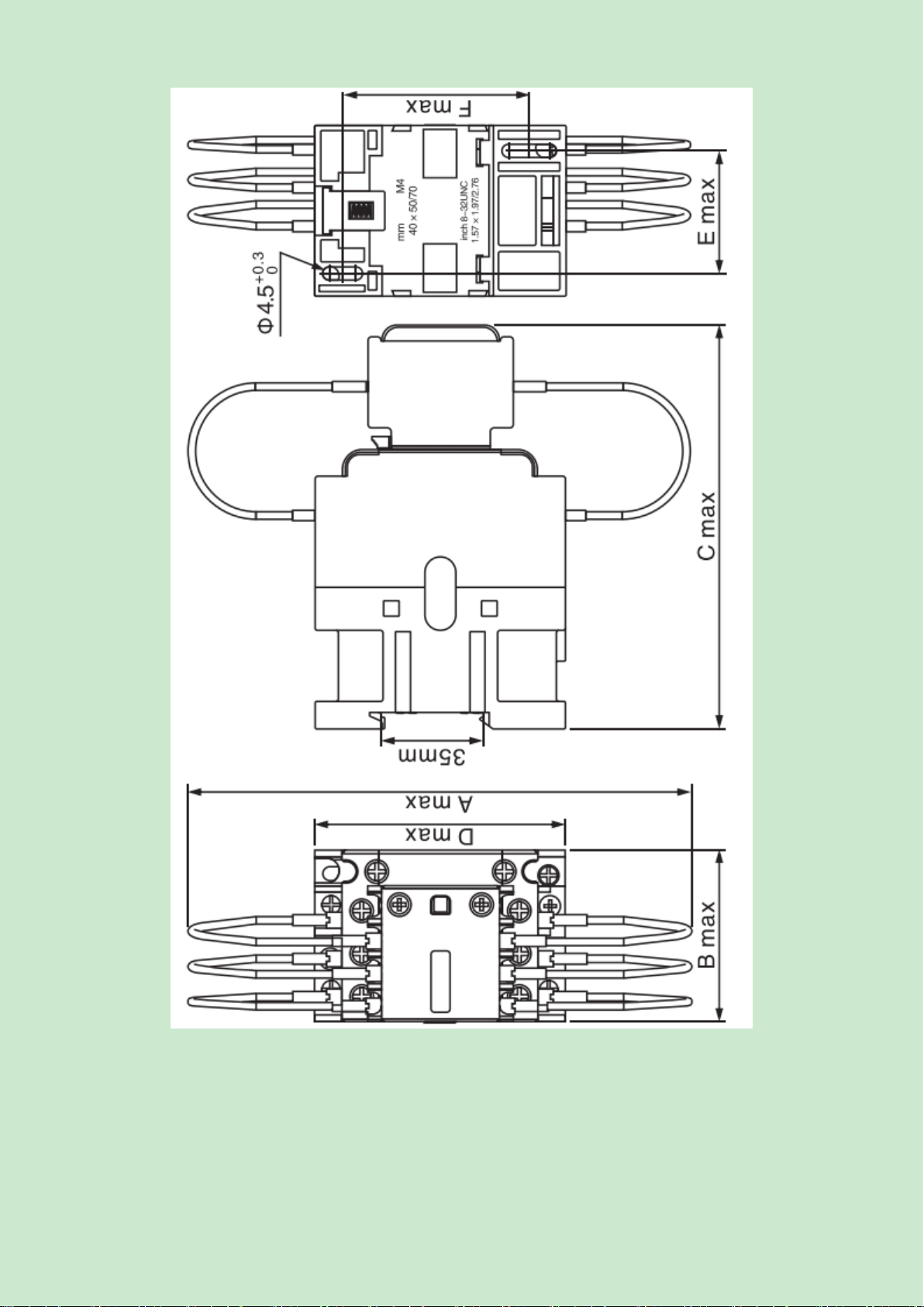
Fig. 2 Outline and installation dimensions of CDC19s-25, 32, 43

Fig. 3 Outline and installation dimensions of CDC19s-63, 95, 115
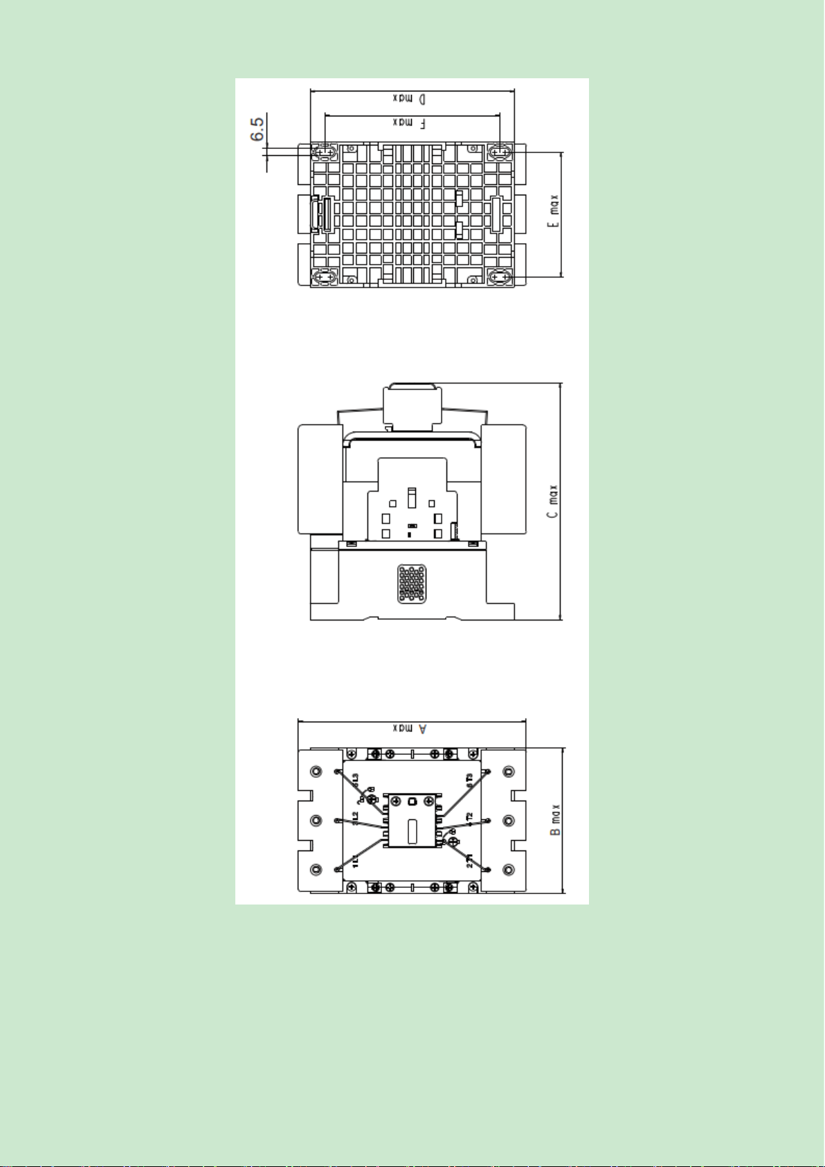
Fig. 4 Outline and installation dimensions of CDC19s-150, 170
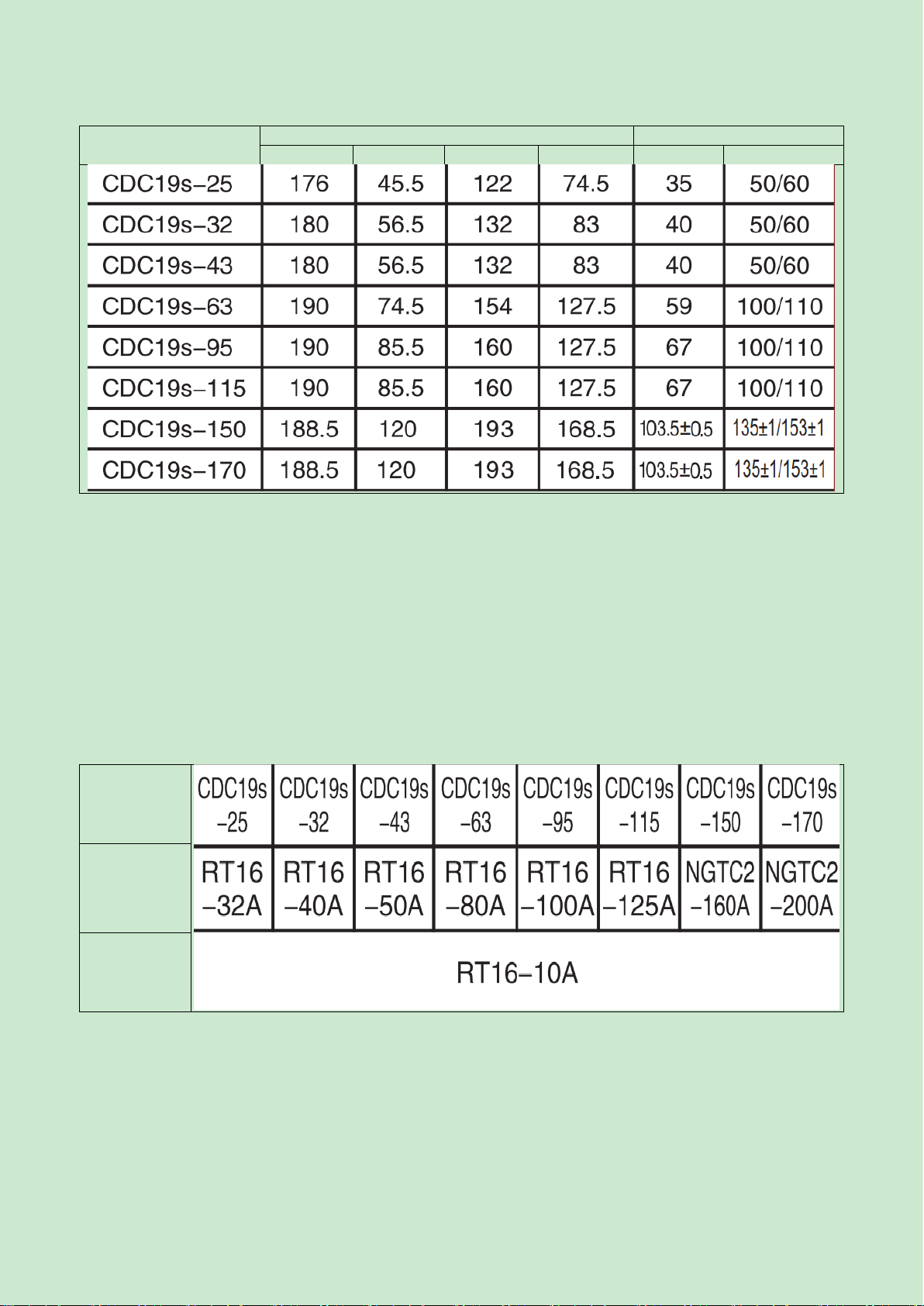
Table 3 Outline and installation dimensions Unit: mm
Model
Outline dimensions
Installation dimensions
Amax
Bmax
Cmax
Dmax
Emax
Fmax
Debugging and Operation
●Check whether the technical parameters of product comply with the operation requirements;
●Please separate the resistance wires between the phases after installation;
●The inlet line and outlet line of contractor must be connected firmly to prevent burns to the terminals and
products due to terminal block overheating caused by loose connection;
●The insulation resistance of the electrical appliance selected for the discharge device in the power factor
compensation equipment shall be greater than √2Ue;
●Power on the control circuit and conduct the no-load operation test, and then connect the load after no
abnormality is found during test;
●Prevent foreign matters falling into the product;
●It is recommended to select SCPD according to type 1 coordinated protection; the model of fuse is shown in
Table below. Table 4 Model of matching fuse
Product model
Model of
matching fuse
of main circuit
Model of
matching fuse
of auxiliary
circuit
●The recommended sectional area and tightening torque of the wire of the terminal block are listed in Table 5.
Table 5 Recommended sectional area and tightening torque of the wire of the terminal block
Product model
CDC19s-
25
CDC19s-
32/43
CDC19s
-63
CDC19s-
95/115
CDC19s-
150/170
Main circuit wiring
Soft wire without terminal
block
One wire
mm2
1...4
1.5...10
4...25
6...50
95mm2
Two wires
mm2
1...4
1.5...6
4...16
6...25
/
Soft wire with terminal block
One wire
mm2
1...4
1...6
4...25
6...50
/
Two wires
mm2
1...2.5
1...4
4...10
6...16
/
Hard wire without terminal
block
One wire
mm2
1...4
1.5...6
4...25
6...50
/
Two wires
mm2
1...4
1.5...6
4...10
6...25
/
Tightenin torque
N.m
1.2
1.8
5
9
12
Control and aux. loop wiring
Soft wire without terminal
block
One wire
mm2
1...4
Two wires
mm2
Soft wire with terminal block
One wire
mm2
1...2.5
Two wires
mm2
Hard wire without terminal
block
One wire
mm2
1...4
Two wires
mm2
Tightenin torque
N.m
1.2
Maintenance and Service
●Tighten the terminal blocks of contractor firmly on a regular basis, and remove the deposited dust, otherwise the
risk of fire or short circuit may occur;
● Small metal particles sprayed around the contactor or on the arc hood should be removed, and the contactor
shall stop when the contact surface is burnt until the base material is exposed.
Fault Analysis and Solution
The common fault analysis and solution see Table 6.

Table 6 Common fault analysis and solution
Fault
Cause
Solution
The iron core cannot
be pulled in or the
suciton force is
insufficient (that is,
the contact is closed
but the iron core is
not completed pulled
in)
1. The power supply voltage is too low or
fluctuates too much;
2. The power capacity of the operating circuit is
insufficient or the wire is broken, wiring is
incorrect and the control contact has poor contact;
3. The technical parameters of coil are inconsistent
with the working conditions;
4. The product itself is damaged (such as coil
broken or burnt, and mechanical movable part
blocked).
1. Incease the power voltage;
2. Increase the power capacity;
replace the line; repair the control
contact;
3. Replace the contactor;
4. Eliminate the blockage fault, and
replace the contactor.
No release or slow
release
1. Contact fusion welding;
2. The mechanical movable part is blocked;
3. There is oil strin or dust sticking to the pole face
of the iron core.
1. Eliminate the fuse welding fault,
and repair or replace contactor;
2. Eliminate the blockage fault;
3. Clean the pole face of the iron
core.
Coils are overheated
or burnt
1. The power voltage is too high or too low;
2. The technical parameters (such as rated voltage,
frequency, on-load factore and applicable working
system) of the coil are inconsistent with the actual
operation;
3. The moving part is blocked;
4. The pole face of iron core is unfatted or stuck
with dust.
1. Adjust the power voltage;
2. Replace the contactor;
3. Eliminate the mechancial
blockage fault;
4. Clean the pole face.
Large noise issued
from the
electromagnets (AC)
1. The power voltage is too low;
2. The magnetic system is skewed or mechanically
blocked, making that the iron core cannot be pulled
in flattly;
3. The pole face of iron core is rusted or intruded
by foreign matter;
4. The short-circuit ring is broken or the pole face
of iron core is worn excessively and uneven.
1. Increase the operating loop
voltage;
2. Adjust the magnetic system or
eliminate the mechanical blockage
fault;
3. Clean the pole face;
4. Replace the contactor.
Contact fusion
welding
1. The operating frequency is too high or the
product is overloaded;
2. Short circuit at the load side;
1. Replaced by an appropriate
contactor:
2. Eliminate short circuit fault.
Resistance wire burnt
The resistance will be burnt if the closing current is
too large beyond the suppression capacity of this
switching capacitor contactor when the contactor is
closed.
Replaced by an appropriate
contactor

Company Commitment
Under the condition that users follow the use and storage conditions and the product are well sealed, within 24
months from the production date, our company will provide repair and replacement service free of charge for any
damage or abnormal operation due to poor manufacture quality. A paid repair will be provided if the warranty
period expires. For any damage due to one of the following situations, a paid repair will be given even if within
the warranty period:
(1) Improper operation, maintenance, or storage;
(2) Modified without permission or improper repair;
(3) Damage due to falling off or caused during installation after purchase;
(4) Force majeure such as earthquakes, fires, lightning strikes, abnormal voltages, and secondary disasters; If
you have any question, please contact the dealer or our company’s customer service department.
Customer service hotline: 400-826-8008
Certificate
DELIXI ELECTRIC LTD
Name: Capacitor changeover contactor
Model: CDC19s Series
This product passes the inspection and is allowed to be
shipped.
Standard: GB/T 14048.4
Inspector: Check 06
Production date: See label on inner box
DELIXI ELECTRIC LTD
Address: Delixi High-Tech Industrial Park, Liushi Town, Leqing City, Zhejiang P/C: 325604
Tel: (86-577) 6177 8888
Fax: (86-577) 6177 8000
Customer Service hotline: 400-826-8008
www.delixi-electric.com
The first edition of this manual was issued on August 2022.
Other manuals for NAVIGATOR Series
4
This manual suits for next models
9
Table of contents
Other Delixi Industrial Equipment manuals

Popular Industrial Equipment manuals by other brands

Lillbacka Powerco
Lillbacka Powerco FINN-POWER P20 MS operating instructions

CM
CM BEAM CLAMP operating instructions

Bernina
Bernina Q Series Assembly instructions

Lippert Components
Lippert Components Power Gear 82-L0356 owner's manual

COREMO OCMEA
COREMO OCMEA D-M User and maintenance manual

Conquip
Conquip Trench Box user guide


