CAB 4014 User manual

Service Manual
4014 / 4016
MADE IN GERMANY
Stroke Applicator

2 2
Family Type
Stroke Applicator 4014...-200
4014...-300
4014...-400
4016...-200
4016...-300
4016...-400
Edition: 02/2019 - Part No. 9009194
Copyright
This documentation as well as translation hereof are property of cab Produkttechnik GmbH & Co. KG.
The replication, conversion, duplication or divulgement of the whole manual or parts of it for other intentions than its original
intended purpose demand the previous written authorization by cab.
Editor
Regarding questions or comments please contact cab Produkttechnik GmbH & Co. KG.
Topicality
Due to the constant further development of our products discrepancies between documentation and product can occur.
Please check www.cab.de for the latest update.
Terms and conditions
Deliveries and performances are effected under the General conditions of sale of cab.
Service Manual
for the following products
Germany
cab Produkttechnik GmbH & Co KG
Karlsruhe
Phone +49 721 6626 0
www.cab.de
USA
cab Technology, Inc.
Chelmsford, MA
Phone +1 978 250 8321
www.cab.de/us
Taiwan
cab Technology Co., Ltd.
Taipei
Phone +886 (02) 8227 3966
www.cab.de/tw
China
cab (Shanghai) Trading Co., Ltd.
Guangzhou
Phone +86 (020) 2831 7358
www.cab.de/cn
France
cab Technologies S.à.r.l.
Niedermodern
Phone +33 388 722501
www.cab.de/fr
Mexico
cab Technology, Inc.
Juárez
Phone +52 656 682 4301
www.cab.de/es
China
cab (Shanghai) Trading Co., Ltd.
Shanghai
Phone +86 (021) 6236 3161
www.cab.de/cn
South Africa
cab Technology (Pty) Ltd.
Randburg
Phone +27 11 886 3580
www.cab.de/za

3
1 Introduction............................................................................................................................................5
1.1 Instructions...............................................................................................................................................5
1.2 Intended Use............................................................................................................................................5
1.3 Safety Instructions....................................................................................................................................5
1.4 Safety Markings .......................................................................................................................................6
1.5 Environment.............................................................................................................................................6
2 Product Description...............................................................................................................................7
2.1 Important Features...................................................................................................................................7
2.2 Technical Data..........................................................................................................................................7
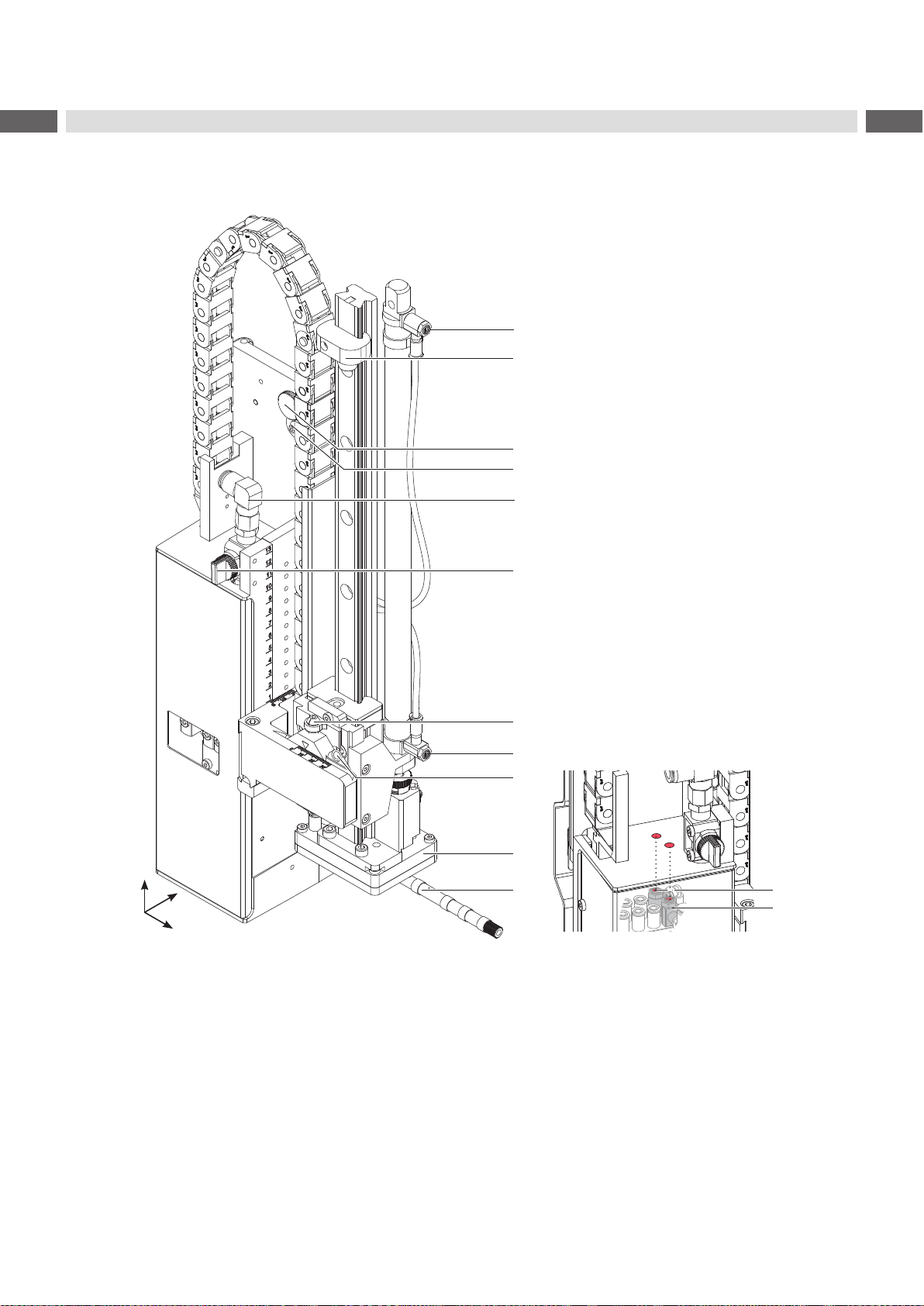
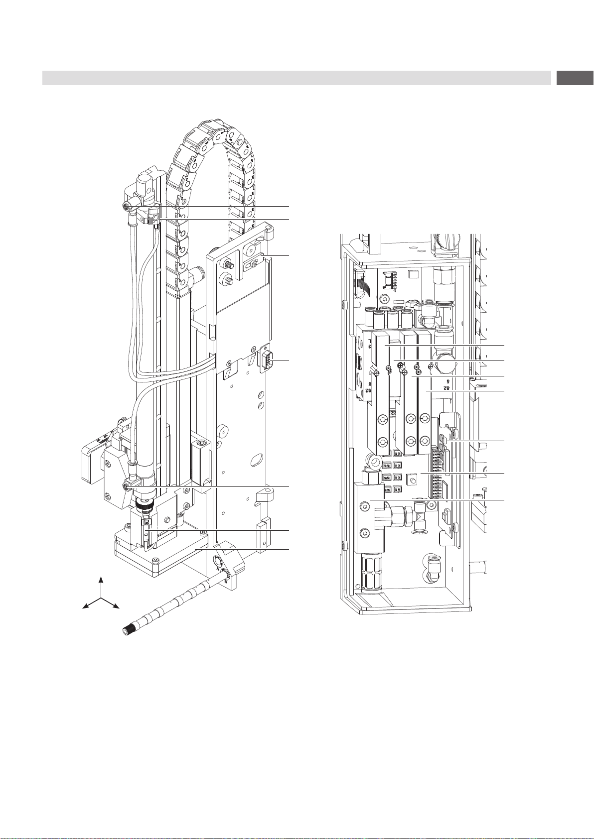
2.3 Overview without Cover...........................................................................................................................8
2.4 Contents of Delivery...............................................................................................................................10
2.5 Pads........................................................................................................................................................11
2.5.1 Universal Pads ..................................................................................................................................11
2.5.2 Roll-on Pad 4100...............................................................................................................................11
2.5.3 Blow Pad 4014L/R-21xx....................................................................................................................11
2.5.4 Corner-wrap Pad 4014L/R-5100 .......................................................................................................11
3 Operation..............................................................................................................................................12
3.1 Standard Operation................................................................................................................................12
3.2 Cleaning.................................................................................................................................................12
4 Error Messages....................................................................................................................................14
4.1 Error Messages of the Printer................................................................................................................14
4.2 Error Messages of the Applicator...........................................................................................................14
5 Installation............................................................................................................................................15
5.1 Factory default Settings .........................................................................................................................15
5.2 Tools.......................................................................................................................................................16
5.3 Mounting and Dismounting the Cover....................................................................................................16
5.4 Mounting the Applicator to the Printer....................................................................................................17
5.5 Transportation Lock................................................................................................................................17
5.6 Mounting the Pad...................................................................................................................................18
5.7 Piercing the Universal Pad Sliding Foil..................................................................................................18
5.8 Preparing the Applicator for the Spring Mounted Pad 401x-4x00..........................................................19
5.9 Mounting the Blow Tube.........................................................................................................................19
5.10 Compressed Air Connection ..................................................................................................................20
6 Adjustments .........................................................................................................................................21
6.1 Pad Adjustments....................................................................................................................................21
6.2 Vacuum Adjustments..............................................................................................................................22
6.3 Adjusting the Blow Tube (Supporting Air)...............................................................................................23
6.4 Adjustment of the Stopper for Blow on Mode.........................................................................................25
6.5 Lifting Speed of Cylinder Z.....................................................................................................................26
6.6 Sensors on Cylinder Z............................................................................................................................27
6.7 End Position Cushioning........................................................................................................................28
6.8 Adjusting the Options for Z-Direction Movement ...................................................................................28
6.9 Labeling from below - Changing the Spring of the Impact Sensor.........................................................29
7 Conguration........................................................................................................................................30
7.1 Method for Changing the Printer Setup..................................................................................................30
7.2 Quick Mode for Setting the Delay Times................................................................................................30
7.3 CongurationParametersoftheApplicator ...........................................................................................31
7.4 Setting the Peel Position........................................................................................................................32
7.5 Activation of Peel-off Mode....................................................................................................................32
8 Test Operation......................................................................................................................................33
8.1 Test Mode without a Print Job................................................................................................................33
8.2 Test Mode with Print Job........................................................................................................................33
Table of Contents

4 4
Table of Contents
9 Spare Parts...........................................................................................................................................34
9.1 Retainer Assembly.................................................................................................................................34
9.2 Pneumatics Retainer Assembly .............................................................................................................35
9.3 Electronics Retainer Assembly...............................................................................................................36
9.4 Guiding Cylinder Assembly 200/300......................................................................................................37
9.5 Guiding Cylinder Assembly 400.............................................................................................................38
9.6 Cylinder Assembly Z 200/300 ...............................................................................................................39
9.7 Cylinder Assembly Z 400 ......................................................................................................................40
10 Drawings...............................................................................................................................................41
10.1 Block Diagram Type 4014/4016.............................................................................................................41
10.2 Pneumatic Drawing Type 4014/4016.....................................................................................................42
10.3 Label Position Type 4014 L/4016 L........................................................................................................43
10.4 Label Position Type 4014 R/4016 R.......................................................................................................44
11 Index......................................................................................................................................................45

5
1 Introduction
1.1 Instructions
Important information and instructions in this documentation are designated as follows:
Danger!
Draws attention to an exceptionally great, imminent danger to your health or life due to hazardous
voltages.
!
Danger!
Draws attention to a danger with high risk which, if not avoided, may result in death or serious injury.
!
Warning!
Draws attention to a danger with medium risk which, if not avoided, may result in death or serious injury.
!
Caution!
Draws attention to a danger with low risk which, if not avoided, may result in minor or moderate injury.
!
Attention!
Draws attention to potential risks of property damage or loss of quality.
i
Note!
Advice to make work routine easier or on important steps to be carried out.
Environment!
Gives you tips on protecting the environment.
Handling instruction
Reference to section, position, illustration number or document.
Option(accessories,peripheralequipment,specialttings).
Time Information in the display.
1.2 Intended Use
• The device is manufactured in accordance with the current technological status and the recognized safety rules.
However, danger to life and limb of the user or third parties and/or damage to the device and other tangible assets
can arise during use.
• The device may only be used for its intended purpose and if it is in perfect working order, and it must be used with
regard to safety and dangers as stated in the operating manual.
• The device applicator mounted on a cab printer of the Hermes+ series is intended exclusively for applying suitable
materials that have been approved by the manufacturer. Any other use or use going beyond this shall be regarded
as improper use. The manufacturer/supplier shall not be liable for damage resulting from unauthorized use; the
user shall bear the risk alone.
• Usage for the intended purpose also includes complying with the operating manual, including the manufacturer‘s
maintenancerecommendationsandspecications.
i
Note!
The complete and current version of the documentation can be found in the Internet.
1.3 Safety Instructions
!
Attention!
Initiation,adjustmentsandchangingofpartsaretobeperformedbyqualiedservicepersonnelonly.
!
Warning!
This is a class A product. In a domestic environment this product may cause radio interference in which
case the user may be required to take adequate measures.

6 6
1 Introduction
• Before mounting the delivered components disconnect the printer from the power supply and close the shutoff
valve of the applicator.
• Only connect the device to other devices which have a protective low voltage.
• Switch off all affected devices (computer, printer, accessories) before connecting or disconnecting.
• In operation, moving parts are easily accessible.
This applies especially for the zone, where the pad is moved between the starting and the labelling position.
During operation do not reach into that zone and keep long hair, loose clothes, and jewelry away. Before any
alterations are undertaken in those areas, close the compressed air shutoff valve.
• The device may only be used in a dry environment, do not expose it to moisture (water splashes, sprays and mist)
• Do not use the device in an explosive atmosphere.
• Do not use the device close to high-voltage power lines.
• Perform only those actions described in this service manual.
Work going beyond this may only be performed by trained personnel or service technicians.
• Unauthorized interference with electronic modules or their software can cause malfunctions.
• Otherunauthorizedworkon,ormodicationstothedevicecanalsoendangeroperationalsafety.
• Alwayshaveserviceworkdonebyaqualiedworkshop,wherethepersonnelhavethetechnicalknowledgeand
tools required to do the necessary work.
• There are various warning stickers on the device. They draw your attention to danger. Warning stickers may
therefore not be removed.
1.4 Safety Markings
1
3
2
1: Risk of injury by moving parts!
2: The cylinder is under pressure
also if the printer is switched off.
Possibility of residual energy!
3: Danger of crushing hands and
ngersbythemovingpad!
!
Attention!
Never remove or cover safety markings!
Replace it in case of damage!
Fig. 1 Safety markings
1.5 Environment
Obsolete devices contain valuable recyclable materials that should be sent for recycling.
Send to suitable collection points, separately from residual waste.
The modular construction of the print module enables it to be easily disassembled into its component parts.
Send the parts for recycling.

7
2 Product Description
2.1 Important Features
• The supporting air and the vacuum as well as the speed of the cylinder are adjustable. That way the applicator
can be adapted to different label materials and sizes.
• To avoid contamination within the vacuum channels they are cleaned by air pressure pulses at the end of each
application.
• For operation within a system the I/O interface of the printer can be used.
2.2 Technical Data
Label transfer method Tamp pad Universal pad Spring loaded
tamp pad Spring loaded
universal pad
4014/16 L/R 11F 4014/16 L/R 1100 4014/16 L/R 31F 4014/16 L/R 3100
Label width in mm for Hermes+4 20 -114 75 - 90 80 - 114 116 /116
for Hermes+6 50 - 174 - 80 - 174 -
Label height in mm 20 - 210 60 - 90 80 - 210 102/152
Compressed air pressure 0.45 MPa (4.5 bar)
Sound pressure level under 74 dB(A)
Product during
labeling xed ¢ ¢ ¢ ¢
in motion - - - -
Labeling onto the
product from the top ¢ ¢ ¢ ¢
from below ¢ ¢ ¢ ¢
sideways ¢ ¢ ¢ ¢
Product height variable ¢ ¢ ¢ ¢
Product distance to lower edge
at cylinder stroke 200 mm up to mm 135 135 130 130
300 mm up to mm 235 235 230 230
400 mm up to mm 335 335 330 330
Immersion depth pad F2) up to mm 120 - 100 -
Cycle time about frequency/min.1) 30 30 25 25
Label transfer method Blow pad Roll-on pad Corner pad
4014/16 L/R 2100 4014/16 L/R 4100 4014/16 L/R 5100
Label width in mm for Hermes+4 20 -114 25 - 114 20 - 114
for Hermes+6 - 50 - 174 -
Label height in mm 20 - 100 80 - 250 60 - 210
Compressed air pressure 0.45 MPa (4.5 bar)
Sound pressure level under 74 dB(A)
Product during
labeling xed ¢-¢
in motion ¢ ¢ -
Labeling onto the
product from the top ¢¢¢
from below ¢ ¢ -
sideways ¢ ¢ -
Product height variable - ¢ ¢
Product distance to lower edge
at cylinder stroke 200 mm up to mm 140 160 1003)
300 mm up to mm 240 260 2003)
400 mm up to mm 340 360 3003)
Cycle time about frequency/min.1) 25 20 20
Table 1 Technical Data
1) Determined at 100 mm stroke below device / smallest label height / print speed 100 mm/s.
2) Immersion depth at applicator >25 mm, the cover of the Hermes+mustbemodied.
3) Depending on label height and division

8 8
2 Product Description
2.3 Overview without Cover
1
2
3
4
5
6
7
8
11
10
support air
vacuum
12
13
9
y
x
z
Fig. 2 Overview - Front View
1 Throttle valve cylinder - move in Z-direction
2 Stopper for the operation mode "Blow on", transport lock
3 Knurled screw for attaching the applicator on the printer
4 Setting screw to adjust the angle between applicator and printer
5 Compressed air connector
6 Shutoff valve
7 Setting screw for vertical adjustment cylinder assembly
8 Throttle valve cylinder - move out Z-direction
9 Screwtoxtheverticalpadposition
10 Pad (customized)
11 Blow tube for supporting air
12 Support air throttle valve
13 Vacuum throttle valve
Front View
Fig. 3 Throttle Valve Vaccum and Support Airt
Throttle valves vacuum/support air

9
2 Product Description
1
16
15
8
18
17
14
19
20
21
22
23
25
24
y x
z
Fig. 4 Overview - Rear View
1 Throttle valve cylinder - move in Z-direction
8 Throttle valve cylinder - move out Z-direction
14 Sensor "Start Position"
15 Locking for hinges
16 Interface to the printer
17 Sensor labeling position
18 Pad - customized
19 Valve Cylinder Z
20 Cover plate
21 Valve Blow air
22 Valve Vacuum and Support air
23 PCB Applicator Control
24 PCB Applicator Interfaces
25 Vacuum Generator
Fig. 5 Overview - Control System
Rear View

10 10
2 Product Description
2.4 Contents of Delivery
4
5
1
3
2
• Applicator (1)
• Screws as part of the pad (2)
• Blow tube - as ordered (3)
• Pad - as ordered (4)
• Pen to make holes (5)
(only for universal pads)
• Documentation
Fig. 6 Contents of delivery
i
Note!
Please keep the original packaging in case the applicator must be returned.
!
Attention!
The device as well as the printing materials will be damaged by moisture and wetness.
Set up label printer with applicator only in dry locations protected from moisture and splashes.

11
2 Product Description
2.5 Pads
2.5.1 Universal Pads
Universal Pad 4014L/R-1100 Spring-mounted Universal Pad 4014L/R-3100
Standard size : 70x60, 90x90 Standard size : 116x102, 116x152
Fig. 7 Universal pad 70x60 Fig. 8 Spring-mounted universal pad 116x152
Universal pads are available in different standard sizes.
According to the size of the label the holes may be pierced into the tamp by the customer. For that purpose a piercing
pin has been included in the delivery contents.
Customizedtampsizesforspeciclabelsizesareavailableonrequest.
2.5.2 Roll-on Pad 4100 2.5.3 Blow Pad 4014L/R-21xx
Fig. 9 Roll-on pad Fig. 10 Blow pad
Roll-on pads are only produced on request and are
customized to suit label sizes. Blow pads are only produced on request and are
customized to suit label sizes.
2.5.4 Corner-wrap Pad 4014L/R-5100
Fig. 11 Corner pad
Corner pads are only produced on request and are customized to suit label sizes.

12 12
3 Operation
3.1 Standard Operation
Check all external connections.
Load the material.
Open the shutoff valve.
!
Attention!
Ensure that the pad is not covered by a label when switching on the printer-applicator system.
Otherwise the vacuum sensor may be calibrated incorrectly.
Switch on the printer.
i
Note!
If the pad is not in the starting position when the printer is switched on an error message will appear on the
display.
Press pause button on the printer.
The applicator will move into the start position and is ready for work.
Press the feed button on the printer.
A synchronization feed is initiated. The processed labels have to be removed manually. After a few seconds the
printer carries out a short backfeed to position the front edge of the next label at the printing line.
i
Note!
This synchronization also has to be carried out when the print job has been interrupted with the cancel button.
Synchronizing is not necessary when the print head was not lifted between print jobs. This also applies if
the printer was powered off between print jobs.
Start a print job.
Start the labelling process via PLC interface.
Error messages during labelling process are shown in the display of the printer Error Messages.
3.2 Cleaning
!
Attention!
Never use solvents and abrasives.
1
Clean the outside surfaces with multi purpose cleaner.
Remove dust particles and leftover label pieces with a soft
brush and/or vacuum cleaner.
The slide foil (1) requires regular cleaning as most of the
dirt will accumulate here.
Fig. 12 Cleaning the pad

13
3 Operation
1
1
2
2
6
7
3
4
5
Fig. 13 Mounting the applicator to the printer
!
Attention!
Initiation,adjustmentsandchangingofpartsistobeperformedbyqualiedservicepersonnelonly.
Service Manual of the Applicator
!
Attention!
Disconnect the printer from the power supply before mounting the applicator!
Ensure the printer is in a stable position!
Connect the compressed air only after mounting the applicator to the printer!
To clean the applicator and printer it is sometimes necessary to turn away or even dismount the applicator from the
printer.
Take care not to adjust the setting screws, throttle valves or other alignment elements. This will enable use of the
applicator directly after cleaning.
Pivot Away/Dismount the Applicator
1. Loosen thumbscrew (5) and pivot the applicator aside.
2. Disconnect SUB-D 15 male connector (6) from the female connector (7) of the printer.
3. Loosen screw (4) and remove the locking plate (3) from the hinges.
4. Lift the applicator from the hinges.
Mount the Applicator
5. With the female parts (1) of hinges hang the applicator on the hinges parts (2) of the printer.
6. Connect the SUB-D 15 male connector (6) to the female connector (7) of the printer.
7. To secure the applicator against slipping out of hinges, loosen screw (4), move metal part (3) under the hinge and
tighten screw (4).
8. Swing the applicator to the printer and tighten the thumbscrew (5).

14 14
4 Error Messages
4.1 Error Messages of the Printer
For detailed information about printer errors (e.g. 'Paper out', 'Ribbon out', etc.) Check the operator's manual of the
printer.
Error treatment:
Clearing the error results.
Press the feed key to synchronize the label feed, remove the left over labels manually.
Press the pause key to quit the error state.
After error correction, the label causing the error will be reprinted.
4.2 Error Messages of the Applicator
Thefollowingtablecontainsanoverviewofapplicatorspecicerrormessagesandtheirpossiblecauses.Italso
suggests methods to resolve the error states:
Error Message Possible Cause
Air pressure ins. Compressed air is switched off
Pressure to low < 4 bar
Pressure to high > 6 bar
Label not depos. Label has not been placed onto the product; after the pad has moved back the label is
still sticking to the pad.
Lower position Pad has not reached the starting position within 2s after the pad has left the labelling
position; or pad has left the starting position without authorization.
Process Error Process of labeling was interrupted via the I/O interface of the printer with the STP
signal.
Re. sensor blk. There has been no change of state of the upper sensor of the cylinder from the start of
the labelling process and the signal of the labelling position sensor.
Upper position Pad is not in the starting position when the printer was switched on.
Pad has not reached the labelling position within 2s after the movement of the pad was
started.
Pad has left the printing position without authorization.
Vac. plate empty Label has not been picked up properly by the pad; or label fell off the pad before it could
be placed onto the product.
Table 2 Error messages of the applicator
Error treatment:
Clear the error results.
Press the pause key to quit the error state.
i
Note!
In the case of errors check the Service Manual for adjustments and settings.
!
Warning!
After the error has been resolved the pad will immediately move back to the starting position!
Dangerofinjurytohandsandngersbythemovingpad!
Do not reach into the area of the moving pad and keep long hair, loose clothes, and jewelry away.
After error correction, the printing of the label causing the error cannot be repeated without restarting the print job
except the error "Vac. plate empty" . In this case, the last label will be printed again after resolution via the pause key
and then pressing the Enter button .
Intheapplicationmode"Apply/Print"sendsthesignal"Printrstlabel"orpressthebutton to send a printed
label to the tamp.

15
5 Installation
5.1 Factory default Settings
i
Note!
Theapplicatorissetupinastandardcongurationbythefactory.Thesevaluesguaranteeareliable
operation.
i
Note!
Inthecaseofacustomerspecicsetupwithspecialmaterialthesettingscandeviatefromthestandard
values.
In this case the standard values in the setup protocol are as follows.
The factory default settings are:
• Connected to a cab Hermes+ printer, vertical
• Used Pad: cab part No.: 5963881 54x36 for L
cab part No.: 5963878 54x36 for R
• Material used for factory default settings: cab part No.: 5556472 54x35.5
• Pressure value of the compressed air: 0.45 MPa (4.5 bar)

16 16
5 Installation
5.2 Tools
Screwdriver with parallel blade 2.5 To adjust the throttle valves and
product sensor
Hexagon key L-wrench 0.8 To adjust the sensors
(in contents of delivery)
2.5 For matched norm parts
(in contents of delivery)
4 Pad adjustments
Changing pad
Flat-round nose straight To mount/dismount tubes
angled
Open spanner SW 8 To change the throttle valves
SW 13 Setting the spring power on the
adapter bolt
SW20 Changing the cylinder
Manometer ± 7 bar Air pressure control
Table 3 Tools
5.3 Mounting and Dismounting the Cover
To initiate the applicator or for adjustments it is necessary to dismount the cover (2).
After these adjustments have been completed remount the cover.
!
Warning!
Do not operate the applicator without cover (2).
Only dismount the cover when servicing the applicator.
2
3
1Dismount
1. Loosen screw (3).
2. Lift off cover (2).
Mount
3. Move the cover (2) over the cylinder assembly.
4. Put in the cylinder (1) through the hole in the cover
(2).
5. Tighten screw (3) to fasten the cover (2).
Fig. 14 Cover

17
5 Installation
5.4 Mounting the Applicator to the Printer
!
Attention!
Disconnect the printer from the power supply before mounting the applicator!
Ensure the printer is standing in a stable position!
Connect the compressed air only after mounting the applicator to the printer!
1
1
2
2
6
7
3
4
5
1. Hang the applicator to the printer via the female
hinges (1) to the male hinges (2) of the printer.
2. Connect the SUB-D 15 male connector (6) to the
female connector (7) of the printer.
3. To ensure the applicator does not slip out of the
hinges, loosen screw (4), move the locking plate
(3) to secure the applicator and tighten screw (4)
again.
4. When pivoting the applicator onto the printer
ensure that the cable is not caught between the
two units.
5. Tighten the thumbscrew (5).
6. Raise the stopper on the rail to enable
movement of the lifting cylinder.
„6.5 Transpor-
tation Lock“
Fig. 15 Mounting applicator to the printer
5.5 Transportation Lock
1
3
2
1
3
2
4
3
Fig. 16 Stopper as transportation lock
When the applicator is delivered, the stopper (2) is mounted on the rod (1). With this stopper (2) the labelling position
for the operation mode "Blow on" can be adjusted. In delivery status the stopper (2) is used as transportation lock.
i
Note!
To reduce the impact energy it is possible to use a stopper with cushioning (4).
Releasing the transportation lock
1. Loosen screw (3) of the stopper (2).
2. Move the stopper (2) along the rod (1) into the position as in operation mode:
- Operation mode "Blow on": 7.4 Adjusting the stopper
- Operation mode "Stamp on" : Move the stopper (2) up to the end of the rod (1).
3. Tightenscrew(3)toxthestopper(2)inposition.

18 18
5 Installation
5.6 Mounting the Pad
1
2
4
5
68
7
3
1. Insert the pins (6) of the pad (8) into the holes
on the bottom of the pad holder (7).
2. Fix the pad (8) to the pad holder (7) with the
screws (1).
3. Insert the vacuum tube (2) and the air blowing
tube(3)intotheirappropriatepush-in-ttings
(4 & 5) of the pad.
Fig. 17 Mounting the pad
!
Attention!
To avoid possible collisions of the pad with other parts of the printer-applicator system, please roughly
align the pad in all directions („7.1 Pad Adjustments“) before connecting the applicator to the
compressed air supply!
5.7 Piercing the Universal Pad Sliding Foil
On the bottom of the pad there are holes for holding the labels in place by vacuum. The universal pad is delivered
with these holes are covered by a sliding foil and must be punctured according to used the label size. For that
purpose a piercing pin is included in the contents of delivery.
!
Attention!
Danger of stabbing injuries in case of inappropriate use.
1 2 3
4
2 mm
1. Place a label (1) on the bottom of the pad
(2). Note the position of the slanted edge (3).
2. Align the label so that it protrudes about 2
mm over the slanted edge.
3. Pierce holes into the sliding foil with the
piercing pin (4) that are clearly covered by
the label as illustrated. Ensure the holes are
free of sliding foil by twisting the piercing pin.
Fig. 18 Piercing the sliding foil of the universal pad
!
Attention!
Do not pierce holes into the sliding foil which are located less than 1 mm from the label's edge as this will
compromisethevacuumsefciency.

19
5 Installation
5.8 Preparing the Applicator for the Spring Mounted Pad 401x-4x00
!
Attention!
Ensure the cylinder assembly does not get damaged or cause injury when loosening screws to perform
adjustments.
Depending on the type of pad being used the cylinder assembly can be mounted at different heights.
When delivered, the pad assembly is mounted in the lowest position as this is suited for most pads.
In case of using a larger pad (e.g. 116x102/116x152) with the applicator 4014/4016 it is necessary to change the
position of the pads z-direction.
5
2
3
1
4
1. Loosen screws (2) and move the pad
assembly with the girder (3) along the adapter
prole(1)untilthescrews(5)canbereached.
2. Loosen screws (5).
3. Movepadassemblywithadapterprole(1)up
one snap point position (4).
4. Fix the cylinder assembly in new position with
screws (5).
5. Tighten screws (2).
Fig. 19 Changing the base height of the cylinder unit
5.9 Mounting the Blow Tube
1 2 3
Fig. 20 Mounting the blow tube
It is possible to rotate the blow tube (4) to optimize the direction of the supporting air for the take over procedure of
the label from printer to applicator.
1. Loosen screw (1).
2. Place the blow tube (3) into the blow tube hole B (2).
3. Tighten screw (1) lightly to secure the blow tube (3). „7.3 Blow Tube and SupportAir Adjustments“

20 20
5 Installation
5.10 Compressed Air Connection
!
Attention!
Adjustments and functionality control were done with a compressed air value of 4.5 bar.
The applicator's operating range is between 4.0 and 6.0 bar.
!
Warning!
When connecting the applicator to compressed air it is considered "IN USE!" Cylinder motion is possible!
Do not reach into the zone of the moving pad and keep long hair, loose clothes, and jewelry away.
2
1
3
4
1. Check that the stop valve (2) is closed as
illustrated.
2. Attach compressed air to connector (1).
3. Open the stop valve (2) by turning it into the
directionofairow.
4. Switch on the printer via the power switch.
It is possible to use an air pressure regulation
unit.
cab offers two versions of air pressure regulators.
• Air pressure regulation unit with included
magnetic valve (3)
Controlling via printer
Interface description of the printer
• Standard version (4)
Fig. 21 Compressed air connection
i
Note!
If the pad is not in the starting position when the printer is switched on an error message will appear on the
display.
Press the pause button on the printer to cancel the error state. The applicator will move into the start
position and is ready for work.
i
Note!
Only mount the air pressure regulation unit as illustrated otherwise the functionality of the air-water
separator cannot be guaranteed.
Other manuals for 4014
1
This manual suits for next models
1
Table of contents
Other CAB Industrial Equipment manuals
Popular Industrial Equipment manuals by other brands

Metso
Metso LOKOTRACK LT110C instruction manual

SCHUNK
SCHUNK PGB 64 Assembly and operating manual

Optea
Optea WDS 50 user manual

Pronomic
Pronomic 19470 user manual

Siemens
Siemens SIVACON 8PS BD2 Series installation instructions

Alpha Technologies
Alpha Technologies ALPHA OUTBACK ENERGY Cordex HP LPS04 Installation & operation manual