Schiedel TecnoFlex Plus User manual

DON'T FORGET TO REGISTER YOUR INSTALLATIONS
AND START EARNING SCHIEDEL INSTALLER REWARDS
See inside for more details
www.schiedel.com/ukwww.schiedel.com/uk
Flexible Liners
Installation Instructions
SAP Issue 5 | 940002172 | April 2019
INCLUDES DETAILS
ON AWARD WINNING
SCREWFIT ACCESSORIES
& SCHIEDEL INSTALLER
REWARDS

2
Contents
Approvals
TecnoFlex Plus is CE Certified to
EN 1856-2 TÜV 0036 CPR 9195 035
respectively with designations:
Application
Approvals
Design Guide
- Mandatory Requirements
Prior to Installation
Connecting Flue Pipe
BS EN 15287-1
- Acceptable Alternative Methods
of Connection
Installation of the Liner
TecnoFlex Plus Accessories
- Top of the Chimney
- Connection from the Appliance
Installation Instructions
Triplelock Accessories
- Top of the Chimney & Connection
from the Appliance
Page 2
Page 2
Page 3
Page 4-5
Page 6-7
Page 8
Page 9-10
Page 11-13
Page 14
Page 17-19
Page 20-21
Page 22-25
Page 26
Page 26
Page 27
Page 27
High Temperature
Applications
Low Temperature
Applications
T600 N1 W V2 L50012 G
T600 N1 W V2 L70012 G
T200 P1 W V2 L50012 O
T200 P1 W V2 L70012 O
Applications
T200 P1 W V2 L50010 O
T300 N1 W V2 L50010 O
Triplelock is CE Certified to
EN 1856-2 TÜV 0036 CPR 9195 043
with designations:
Triplelock is a single wall stainless steel flexible flue liner designed for atmospheric gas and
kerosene appliances where the flue gas temperature does not exceed 260°C.
TecnoFlex Plus is a twin skin flexible chimney liner designed for gas, oil and multi-fuel, where
the maximum flue gas temperature does not exceed 600°C.
Application
Connection to a Fluebox
Design, Installation & Assembly
Frequently Asked Questions
After Installation
Notice Plate
Product Guarantee
Schiedel Installer Rewards

3
Design Guide
MANDATORY REQUIREMENTS
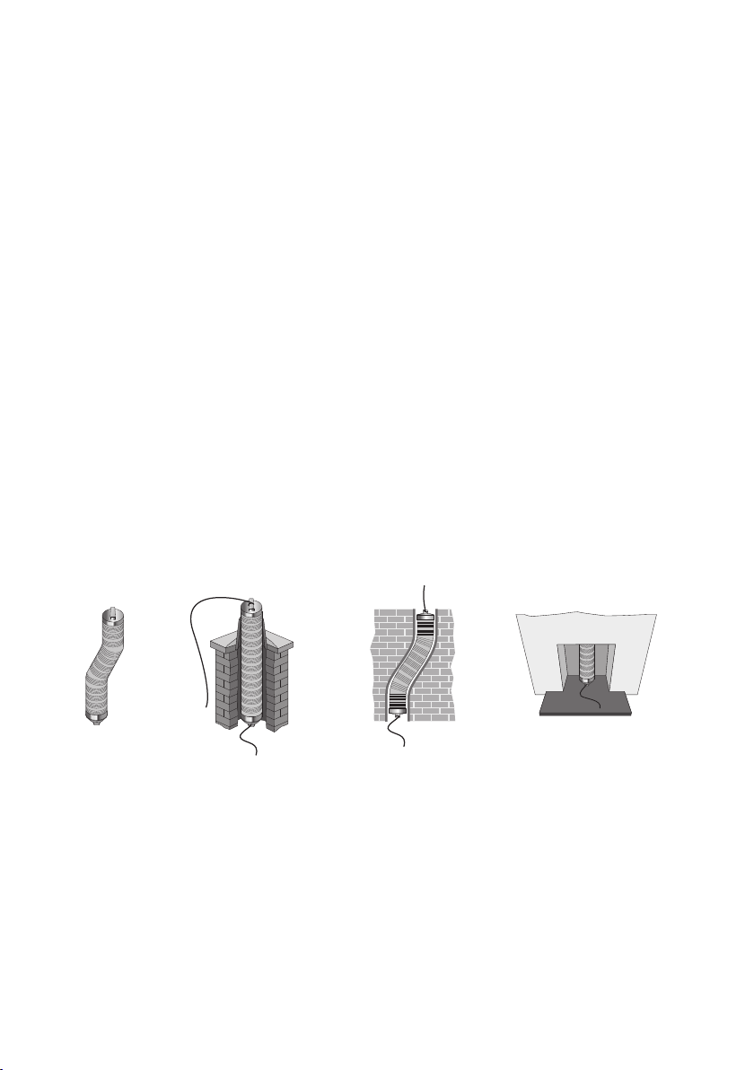
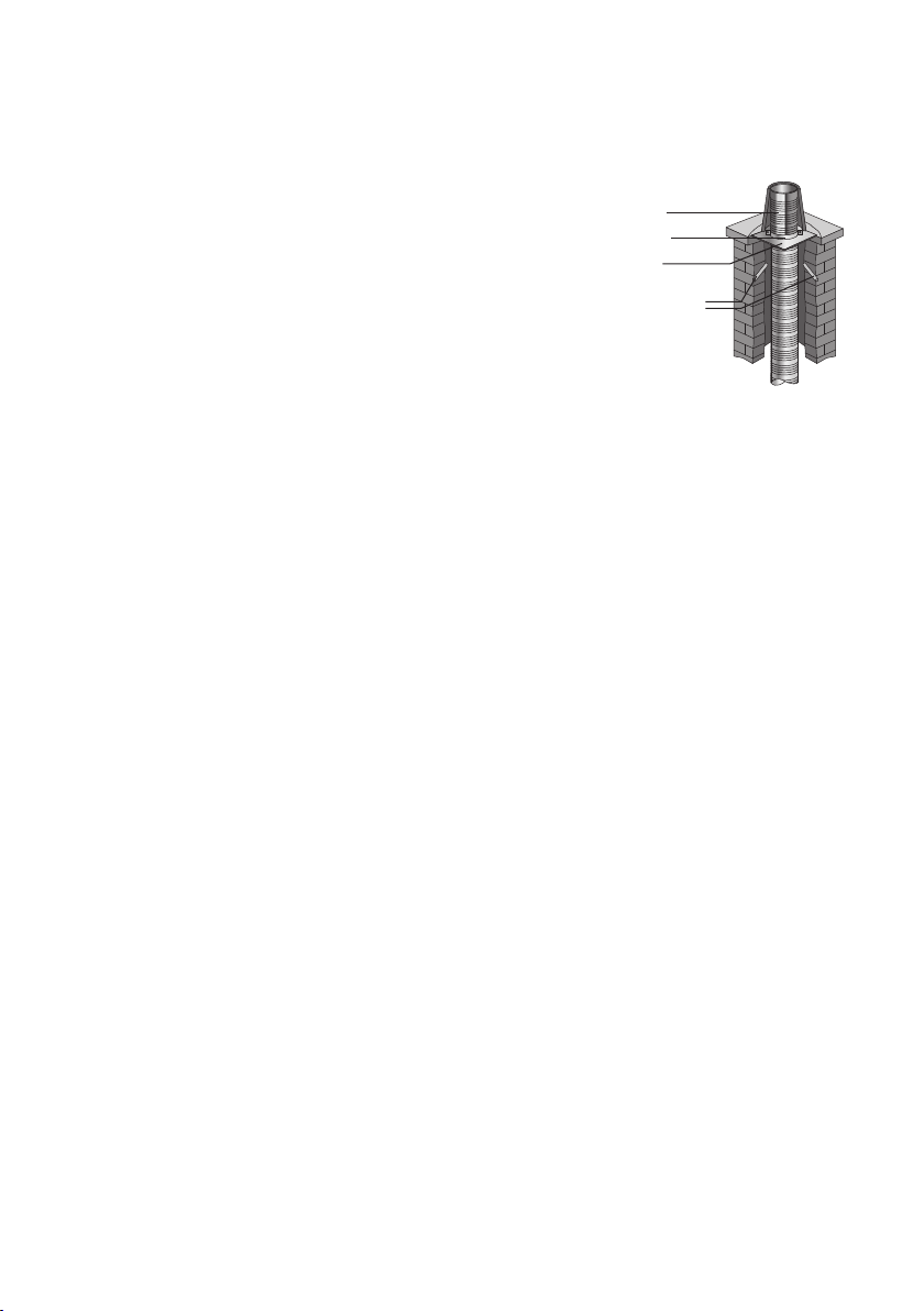
Building Regulations Document J requires that a flexible flue liner can only be installed
completely enclosed inside a masonry chimney. A non masonry enclosure such as timber or
plasterboard boxing in is not acceptable.
The type of flue liner permitted depends on the fuel to be used, the type of appliance and the
type and year of chimney construction in which it is to be fitted.
Building Regulations Document J, outlines different requirements for relining masonry chimneys
built before and after 1st February 1966. This is summarised in the table below.
Connection to an appliance which is not connected to the fuel supply, should be carried out
by a competent person. We recommend the use of HETAS approved installers for solid fuel
applications. If installation is carried out by a non HETAS registered installer, the installation
must be certied by a local Building Control inspector. Connection to an appliance that is
connected to the fuel supply must be carried out by a Gas Safe (Gas) or OFTEC (Oil) registered
installer.
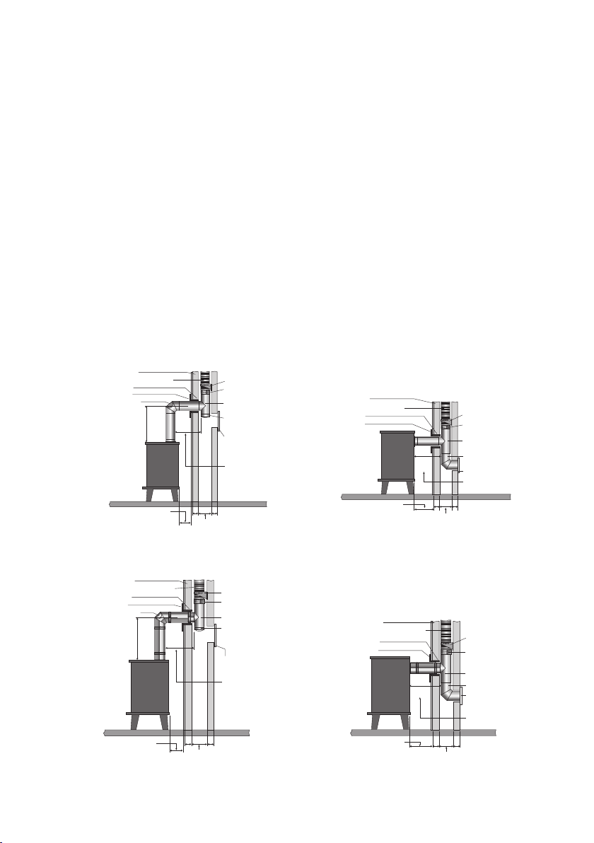
The design guide must be read in conjunction with the detailed component installation
instructions.
For full design and installation details the key referral documents are:
• BS EN 1856-2: Connecting Flue Pipes
• BS EN 1856-2: Flue Liners
• BS EN 1859: Metal Chimneys - Testing Methods
• BS EN 1443: Chimneys - General Requirements
• BS EN 15287-1: Chimneys. Design, installation and commissioning of chimneys. Chimneys for
non-room sealed heating appliances.
• Approved Document J: - Combustion appliances and fuel storage systems (England & Wales)
• DFP Technical Booklet L: - Combustion appliances and fuel storage systems (NI)
• Technical Handbook (Domestic & Non Domestic),Section 3 - Environment (Scotland)
• Appliance Installation Instructions and related standards. Other standards covering specific
applications will also be relevant and must be adhered to.
Ensure all chimney components are available and check them to ensure there has been no
damage. Do not use damaged components.
Appliance Chimneys built before 1.2.1966 Chimneys built after 1.2.1966
Gas Burning
Output up to 45kW
Triplelock can be used in unlined
chimney on dry applications.
Triplelock can be used in lined
chimney on dry applications.
Kerosene Burning
Output up to 45kW
Triplelock can be used in unlined
chimney on dry applications.
Triplelock can be used in lined
chimney on dry applications.
Gas/Oil Burning
Output up to 45kW
TecnoFlex Plus can be used in
unlined chimney on wet and dry
applications.
TecnoFlex Plus can be used in
lined chimney on wet and dry
applications.
Solid Fuel Burning
Output up to 45kW
TecnoFlex Plus can be used in
unlined chimney.
TecnoFlex Plus can be used in
lined chimney.

4
Prior to Installation
PRIOR TO INSTALLATION
In all cases the chimney should be inspected for deterioration and if necessary any remedial
work required should be carried out. The chimney should be swept by a suitably qualied
chimney sweep who would provide a certicate after sweeping and checking, which should be
retained for future reference. A list of HETAS registered sweeps can be found at www.hetas.
co.uk It will be necessary to check that the flaunching at the top of the stack is not cracked, and
if so replaced. The brickwork pointing and the flashings should be checked to ensure they are in
good order and corrected as necessary. This is required to prevent ingress of rainwater, which,
if mixed with carbon deposits on the inside wall of the chimney, could then damage the fabric of
the building and the chimney liner.
USE OF FLEX TESTER KIT
Prior to installation of the Flex, we recommend that a test length of approx., 1.5m with a nose
cone attached to each end, is pulled through the chimney to ensure that the chimney is suitably
sized and free from obstructions. Failure to do so may lead to the warranty being invalidated on
the Flex if damage has been caused due to snagging on an obstruction.
The tester kit should be pulled down the chimney using a nose cone and string/rope. A re-
usable 1.5m test length complete with two nose cones is available in the TecnoFlex Plus range.
Alternatively nose cones can be purchased separately or as part of a Flex Installation kit.
Flex Tester Kit Flex Tester Kit
entering through
chimney pot
Flex Tester Kit
emerging through
replace.
Flex Tester Kit
going around
an offset

5
Prior to Installation
VENTILATION
It is very important that sufficient air for combustion is provided to the room containing the
appliance, to enable correct and efficient working of the system. Reference should be made to
the appliance manufacturer’s instructions and recommendations are also given in the Building
Regulations Document J.
CARBON MONOXIDE ALARMS
The carbon monoxide alarms should comply with BS EN 50291:2001.
Where a new or replacement fixed solid fuel appliance is installed in a dwelling, a carbon
monoxide alarm must be provided in the room where the appliance is located.
Please follow manufacturers instructions with regards to siting and fixing or alternatively :-
a) On the ceiling at least 300mm from any wall or if it is located on a wall, as high up as possible
(above any doors and windows), but not within 150mm of the ceiling and
b) between 1m and 3m horizontally from the appliance.
N.B Provision of a carbon monoxide alarm should not be regarded as a substitute for correct
installation and regular servicing.
DELIVERY TO SITE AND STORAGE
Components should be carefully transported and off loaded. They should be inspected to
ensure they have not been damaged, and should be stored off the ground and under cover so
that they are protected from accidental damage and the adverse effects of weather.

6
Connecting Flue Pipe
CONNECTION TO THE APPLIANCE OR FLUE BOX
The connection to the appliance should be made using fire cement/rope or high temperature
sealant to ensure a positive seal. Where TecnoFlex Plus is to be fitted to the top of an open fire
place, a Schiedel Rite-Vent gather unit should be fitted into the throat of the chimney connected
to the TecnoFlex Plus and sealed off.
When connecting Triplelock flex to a Schiedel Rite-Vent flue box, the flexible liner simply
pushes directly on to the fast fix spigot. No sealant is required.
When making a connection to a fluepipe in another product type, such as rigid stainless steel
single or double wall or vitreous enamel, then the appropriate Schiedel approved connector to/
from flexible should be used. The connector should be suitably sealed to the appliance spigot
ensuring a gas tight joint.
CONNECTING FLUE PIPE DIAMETER
Connecting Flue Pipe Diameter size should be as recommended by the appliance manufacturer.
Under all circumstances the operational requirements of the appliance and the configuration of
the flue must satisfy the flue sizing requirements of EN13384-1.
DISTANCE TO COMBUSTIBLES
In accordance with building regulations, it is essential that the correct distance to combustible
material is maintained on connecting flue pipes. On solid fuel applications, where there is a risk
of soot fire, on unmeasured (NM) designated single wall product, this distance is 3 x ØInt of
the pipe, e.g. for Ø125mm the distance is 375mm and for Ø150mm the distance is 450mm to
combustibles on both painted and non painted variants. On measured (M) single wall or double
wall products this distance will be as declared by the chimney manufacturer.
CONNECTING FLUE PIPE ROUTE
Connecting flue pipes should only be used to connect appliances to a Chimney. They should
not pass through any roof space, partition, internal wall or floor, except to pass directly into a
chimney through either a wall of the chimney or a floor supporting the chimney.
Connecting flue pipes should be located as to avoid igniting combustible material.
On solid fuel appliances the maximum length of a connecting flue pipe is 2m. This distance is
reduced to 1.5m if any of the acceptable alternative methods of connection are adopted as per
BS EN15287-1. (See p.6 for full details.)
On appliances with a top outlet, it is recommended that a vertical run of at least 600mm should
be allowed immediately above the appliance prior to any change of direction.
On appliances with a rear outlet, it is recommended that there is maximum of 150mm in the
horizontal run however under certain conditions, as described in alternative methods in BS EN
15287-1, this may be increased to 450mm. (See p.6 for full details.)

7
Connecting Flue Pipe
Within a system (Chimney + Connecting Flue Pipe) there should be no more than 4 changes of
direction of maximum 45˚. 90˚ Factory made bends or tees within the system may be treated
as being equal to two 45˚ bends (as per Document J of the Building Regulations issued October
2010).
INSPECTION
On solid fuel applications to conform to Building Regulations, provisions should be made to
enable a chimney to be inspected and cleaned.
An inspection pipe, inspection elbow or a 90° or 135° Tee with tee cap can form a suitable
inspection point (unless cleaning/inspection can be done through the appliance). To aid cleaning,
sufficient distance should be left between changes of direction to permit the safe passage of
cleaning brushes within the system. This is particularly important on solid fuel applications. It is
recommended that chimneys serving solid fuel appliances be swept as frequently as necessary,
but at least twice a year.

8
BS EN 15287-1
Acceptable alternative Methods of connection
No further bends
allowed on this
configeration
FlexibleTwin Wall Chimney Liner
Inspection/
Cleanout Door
Inspection Bend
Wall Sleeve
Trim Collar
Chimney Wall
Tee Piece
Tee Cap for
Debris Collection/
Cleaning Access
225 square
(9” x 9”)
225 square
(9” x 9”)
For minimum distance for this
configuration check manufacturers
distance to combustibles
For minimum distance for this
configuration check manufacturers
distance to combustibles
600 min
Support Bracket
Single Wall to
Flex Connector
450mm
MAX
450mm
MAX
Measured from back
of connecting flue
pipe to flue liner
Wall Sleeve
Trim Collar
100 100
100 100
FlexibleTwin Wall Chimney Liner
Chimney Wall
Support Bracket
Swept Elbow
Sweep access
Tee Piece
Single Wall to
Flex Connector
Measured from back
of appliance to flue liner
For minimum distance for
this configuration check
manufacturers distance
to combustibles
Wall Sleeve
Trim Collar
100100
225 square
(9” x 9”)
Flexible Twin Wall Chimney Liner
Chimney Wall
Support Bracket
Swept Elbow
Sweep access
Tee Piece
Single Wall to
Flex Connector
450mm
MAX
Measured from
back of appliance
to flue liner
Flexible Twin Wall Chimney Liner
Inspection/
Cleanout Door
Inspection Bend
Wall Sleeve
Trim Collar
Chimney Wall
Support Bracket
Tee Piece
Tee Cap for
Debris Collection/
Cleaning Access
Single Wall to
Flex Connector
225 square
(9” x 9”)
450mm
MAX
For minimum distance for
this configuration check
manufacturers distance
to combustibles
Measured from back
of connecting flue pipe
to flue liner
600 min
100100
No further bends
allowed on this
configeration
No further bends
allowed on this
configeration
FlexibleTwin Wall Chimney Liner
Inspection/
Cleanout Door
Inspection Bend
Wall Sleeve
Trim Collar
Chimney Wall
Tee Piece
Tee Cap for
Debris Collection/
Cleaning Access
225 square
(9” x 9”) 225 square
(9” x 9”)
For minimum distance for this
configuration check manufacturers
distance to combustibles
For minimum distance for this
configuration check manufacturers
distance to combustibles
600 min
Support Bracket
Single Wall to
Flex Connector
450mm
MAX
450mm
MAX
Measured from back
of connecting flue
pipe to flue liner
Wall Sleeve
Trim Collar
100 100 100 100
FlexibleTwin Wall Chimney Liner
Chimney Wall
Support Bracket
Swept Elbow
Sweep access
Tee Piece
Single Wall to
Flex Connector
Measured from back
of appliance to flue liner
For minimum distance for
this configuration check
manufacturers distance
to combustibles
Wall Sleeve
Trim Collar
100100
225 square
(9” x 9”)
Flexible Twin Wall Chimney Liner
Chimney Wall
Support Bracket
Swept Elbow
Sweep access
Tee Piece
Single Wall to
Flex Connector
450mm
MAX
Measured from
back of appliance
to flue liner
Flexible Twin Wall Chimney Liner
Inspection/
Cleanout Door
Inspection Bend
Wall Sleeve
Trim Collar
Chimney Wall
Support Bracket
Tee Piece
Tee Cap for
Debris Collection/
Cleaning Access
Single Wall to
Flex Connector
225 square
(9” x 9”)
450mm
MAX
For minimum distance for
this configuration check
manufacturers distance
to combustibles
Measured from back
of connecting flue pipe
to flue liner
600 min
100100
No further bends
allowed on this
configeration
No further bends
allowed on this
configeration
FlexibleTwin Wall Chimney Liner
Inspection/
Cleanout Door
Inspection Bend
Wall Sleeve
Trim Collar
Chimney Wall
Tee Piece
Tee Cap for
Debris Collection/
Cleaning Access
225 square
(9” x 9”)
225 square
(9” x 9”)
For minimum distance for this
configuration check manufacturers
distance to combustibles
For minimum distance for this
configuration check manufacturers
distance to combustibles
600 min
Support Bracket
Single Wall to
Flex Connector
450mm
MAX
450mm
MAX
Measured from back
of connecting flue
pipe to flue liner
Wall Sleeve
Trim Collar
100 100
100 100
FlexibleTwin Wall Chimney Liner
Chimney Wall
Support Bracket
Swept Elbow
Sweep access
Tee Piece
Single Wall to
Flex Connector
Measured from back
of appliance to flue liner
For minimum distance for
this configuration check
manufacturers distance
to combustibles
Wall Sleeve
Trim Collar
100100
225 square
(9” x 9”)
Flexible Twin Wall Chimney Liner
Chimney Wall
Support Bracket
Swept Elbow
Sweep access
Tee Piece
Single Wall to
Flex Connector
450mm
MAX
Measured from
back of appliance
to flue liner
Flexible Twin Wall Chimney Liner
Inspection/
Cleanout Door
Inspection Bend
Wall Sleeve
Trim Collar
Chimney Wall
Support Bracket
Tee Piece
Tee Cap for
Debris Collection/
Cleaning Access
Single Wall to
Flex Connector
225 square
(9” x 9”)
450mm
MAX
For minimum distance for
this configuration check
manufacturers distance
to combustibles
Measured from back
of connecting flue pipe
to flue liner
600 min
100100
No further bends
allowed on this
configeration
Top Outlet Twin Wall Connecting Flue Pipe
into Re-lined Masonry Chimney
Rear Outlet Twin Wall Connecting Flue Pipe
into Re-lined Masonry Chimney
Where a horizontal connecting flue of more than 150mm is required to connect a solid fuel
fired appliance to a chimney, an installation method as per the examples below may be used
provided the following criteria is met:-
a. The maximum length of horizontal connecting flue pipe does not exceed 450mm;
b. A Defra exempt appliance or an appliance, which is limited to burning authorised smokeless
fuel only, is installed;
c. A calculation according to BS EN 13384-1 has indicated safe operation of the proposed
configuration, and the results of the calculation are left with the householder along with the
appliance installation instructions;
d. The appliance manufacturer agrees in writing to the proposed configuration;
e. The chimney manufacturer agrees in writing to the proposed configuration;
f. The total length of single wall connecting flue pipe is not more than 1.5m;
g. The appropriate distances to combustible materials from both the appliance and the
connecting flue pipe are maintained.
Top Outlet Single Wall Connecting Flue Pipe
into Re-lined Masonry Chimney
Rear Outlet Single Wall Connecting Flue Pipe
into Re-lined Masonry Chimney
NOTE: These alternative methods do not apply to Republic of Ireland.

9
SUPPORT COMPONENTS
All support components have been tested and approved for the mechanical performance declared
by Schiedel Chimney Systems Ltd.
Triplelock, which is used exclusively on gas and oil applications, is relatively light and can be
supported at the top of the chimney using a clamp plate fixed to the top of the masonry stack.
TecnoFlex Plus, however, is heavier and must be supported at both top and bottom of the stack.
At the top of the stack there are two alternatives:
1. Plate and clamp fixed directly to the existing masonry stack
2. Pot Hanger/ Combined Pot Hanger & Terminal supporting the weight of the flex using the
existing chimney pot.
At the base of the stack a bottom support bracket should be used.
Installation of the Liner
HANDLING
Suitable PPE (Personal Protection Equipment) must be used when handling stainless steel
flexible liners and accessories. PPE advised: Strong industrial gloves plus long sleeved overalls.
LINER ORIENTATION
It is essential in the case of TecnoFlex Plus that the liner is installed the right way up. The arrow
on the outside of the liner indicates the direction of flue gas flow and must be pointing upwards
towards termination. Triplelock Flex can be installed either way up.
CUTTING THE LINER TO THE CORRECT LENGTH FOR THE CHIMNEY
After the length of flue liner has been connected to the appliance, allow a sufficient length
of liner to protrude above the clamp plate to secure the terminal and then cut, using suitable
cutting equipment. At all times extreme care must be taken when cutting the liner and strong
industrial gloves plus long sleeved overalls should be worn as cut edges are very sharp. In
addition, any tape secured to the ends of the liner, which is provided for safe handling prior to
installation, must be removed before completion and commissioning of the full system.
BENDING OF THE LINER
Great care should be taken to
avoid overbending or kinking
the liner on installation. The
minimum bending radii are
shown in the table alongside.
Minimum Bending Radius
Product 80 100 125 155 180 200 230 250 300
Triplelock -250 315 390 450 500 575 625 750
TecnoFlex
Plus
240 300 375 465 540 600 690 750 900

10
Installation of the Liner
INSULATION
Where the chimney is highly exposed or in a large void, then insulation should be considered.
If insulation is required, granules such as Vermiculite, should be poured in around the liner
from the top of the stack after fitting a suitable closure plate at the bottom of the system.
Alternatively a solid tube of high quality insulation can be used.
Under all circumstances, the chimney stack must be fully weather proofed prior to the
installation of the liner and any insulation material. Failure to do so will render the warranty null
and void.
SEALING THE FLUE LINER TO THE CHIMNEY POT
The plate and clamp holding the liner to the chimney top should be secured to the stack. To
weather the top of the chimney stack, seal any gaps between the liner installation and the
chimney pot using appropriate acid resistant mortar.
VENTILATION
Where TecnoFlex Plus is used serving a solid fuel appliance,
ventilation between the liner and the inside of the chimney
will be required. This is provided by installing two 15mm pipes
into the masonry at the top of the stack just below the top
plate and clamp, at an angle to prevent the ingress of rainwater.
lt would also be necessary to install a vent at the base of the
stack above the debris plate or the gather unit. This should be
an air brick or vent of 20cm (see Fig. 8, 9 ,10 p.10). If the cavity
is to be insulated with pearlite, or tube wrap insulation, then
two 15mm pipes at the top of the stack to allow any moisture
in the insulation to evaporate freely, must still be provided.
Top Clamp
Top Plate
15mm
Ventilation Pipes
Top Ins er t

11
Tecnoflex Plus Accessories
Connecting to Terminals
Fig. 1 Fig. 2
Chimney Pot
TecnoFlex Plus
Liner
Screw Fit
Combined Terminal
Chimney Pot
Strap
Integral
Storm Collar
TecnoFlex Plus
Liner
Chimney Pot
Chimney Pot
Strap
Screw Fit
Combined Terminal
Integral
Storm Collar
TecnoFlex Plus
Liner
Chimney Pot
Strap
Screw Fit
Combined Terminal
Integral
Storm Collar
Fig. 3 Fig. 4
Fig. 5
Flaunching Flaunching
Top Clamp Top Clamp
Top Plate Top Plate
Top Ins er t
Chimney Pot
Screw Fit Terminal
Screw Fit
Combined Terminal
Screw Fit
Pot Hanger
Fixing Strap Fixing Strap
Integral Storm Collar Integral Storm Collar
Chimney Pot Chimney Pot
TecnoFlex Plus
Liner
TecnoFlex Plus
Liner
Fig. 6

12
Tecnoflex Plus Accessories
Pot Hanger
Combined Pot Hanger
& Terminal
Top Clamp
Terminal
COMBINED POT HANGER & TERMINAL
The combined pot hanger and terminal supports the weight
of up to 15m of TecnoFlex Plus using the existing chimney
pot as an anchor point. The flex is pulled down the existing
chimney stack using the nose cone (see p.13). Once the flex is
in position at the base of the stack, with the single wall to flex
adaptor fitted in place through the closure plate, at the top
of the chimney, the flex protruding through the chimney pot
should be cut off level with the top of the pot. The threaded
adaptor on the bottom of the terminal is then screwed onto
the outside of the TecnoFlex Plus liner (see Fig.1) until the
storm collar rests on the top of the chimney pot. The three
straps which are welded to the underside of the collar, are
located to the outside of the pot (see Fig.2 opposite). The
fixing strap in the kit is then fastened over these three straps,
leaving approximately 50mm protruding below. The fixing strap
is tightened into place using a screwdriver. The protruding
ends on the three straps are then bent upwards into a loop
around the fixing strap (see Fig.3).
POT HANGER
The pot hanger is installed in the same way as the combined
pot hanger and terminal (See Fig.1,2 & 4 opposite).
TERMINAL
The screw fit terminal is used in combination with the plate
and clamp (see Fig.6 opposite). The adaptor on the bottom
of the terminal is screwed on to the flex (see Fig.1). Cement
flaunching is then used up to and around the base of the
terminal to make the system weather tight.
TOP CLAMP
The top clamp is used in combination with the top plate to
support the weight of the liner at the top of the stack. The
split band passes around the TecnoFlex Plus liner and is then
tightened in place using the nuts and bolts provided. The band
then rests on top of the top plate (see Fig.5 opposite). The top
clamp will support the weight of up to 20m of TecnoFlex Plus.

13
Tecnoflex Plus Accessories
TOP PLATE
The top plate is used in combination with the top clamp to
support the weight of the liner at the top of the stack. (see
Fig.5 opposite)The top plate should be fixed securely in place
and flaunched to make weather proof
TOP INSERT
A top insert should be used to protect the top of the flex
inside the chimney pot (see Fig.5 opposite). The area between
the flex and the chimney pot should be sealed to prevent
water ingress.
ADAPTOR TECNOFLEX PLUS TO PRIMA PLUS
The adaptor from TecnoFlex Plus can be used as an alternative
to the top insert, or to connect from TecnoFlex Plus to Prima
Plus product within the chimney stack. It is secured to the flex
as shown in Fig.1 opposite. The area between the adaptor and
the chimney pot should be sealed to prevent water ingress.
Adaptor TecnoFlex Plus
to Prima Plus
Top Inser t
Top Plate

14
Installation Instructions
Connection from the Appliance
Fig. 7
Fig. 9
Typical Open Fire Installation
Fig. 8
Typical Stove Installation
Top Insert
Chimney Pot
Flaunching
Top Clamp
Top Plate
15mm
Ventilation Pipes
Weatherproof Seal
TecnoFlex Plus Liner
Closure Plate
Gather Unit
Fireback
Bottom Support
Bracket
Fig. 10
Typical Boiler Installation
Closure Plate
135° Tee
Draincap
Prima Plus
Connecting
Flue Pipe
Adaptor
Prima Plus to TecnoFlex
Plus
Appliance
Bottom Support
Bracket
Drain Pipe
(by others)
TecnoFlex Plus Liner
Available in cut lengths or
as packs containing the Top
Clamp and Top Plate.
Bottom
Support Bracket
To secure TecnoFlex Plus.
Closure Plate
Adaptor Kit
(closure ring xed to
underside of closure plate)
Prima Smooth
or Prima Plus

15
CE Approved Adaptor Range
Adaptor and
Increasing Adaptor
Plain End to
TecnoFlex Plus
Extended Adaptor
Plain End to
TecnoFlex Plus
Bottom/Intermediate
Support
Gather Unit
Closure Plate
Adaptor Kit
* CE approved to EN1856-2
*ADAPTOR AND INCREASING ADAPTOR PLAIN END
TO TECNOFLEX PLUS
The adaptor is attached to the TecnoFlex Plus (see Fig. 7
opposite) by screwing the adaptor in a clockwise direction
until the edge of the TecnoFlex Plus is located between the
liner and the threaded outer wall of this component. On
high temperature applications, no sealant is required on the
screwfit joint. The plain end of the adaptor protrudes through
the hole in the closure plate at the base of the chimney stack.
The protruding end of the adaptor then fits inside the vitreous
enamel or stainless steel stove pipe. This joint between the
plain spigot and the stove pipe should be sealed with fire
cement/rope or appropriate high temperature sealant.
*EXTENDED ADAPTOR PLAIN END TO TECNOFLEX
PLUS
Installed as per adaptor Plain End to TecnoFlex Plus.
*CLOSURE PLATE ADAPTOR KIT
Available in two styles: One and two piece.
The two piece consists of two parts, a ring and an extended
plain end to TecnoFlex Plus adaptor, this adaptor is fitted as
per the adaptor plain end to TecnoFlex Plus. The ring is then
slid up around the spigot and fastened to the underside of the
closure plate to provide a neat aesthetic finish on site (see Fig.
8 opposite).
The one piece consists of a plain end to Tecnoflex Plus adaptor
and a fixed ring, this adaptor is fitted as per the adaptor plain
end to TecnoFlex Plus, fastened to the underside of the closure
plate to provide a neat aesthetic finish on site.
GATHER UNIT
The TecnoFlex Plus is fastened inside the socket protruding
from the top of the gather unit and the joint sealed using fire
cement/rope or appropriate high temperature sealant. The
gather should then be fixed to the inside of the masonry
chimney to create a seal with the chimney wall (See Fig. 9
opposite).
BOTTOM/INTERMEDIATE SUPPORT
The support bracket is used to fasten the liner to the wall of
the masonry chimney, to prevent lateral movement during
sweeping of the chimney (See Fig. 8, 9 & 10 opposite).

16
Eccentric Increaser
Plain End to
TecnoFlex Plus
Adaptor
Prima Plus to
TecnoFlex Plus
Adaptor
Prima Smooth to
TecnoFlex Plus
CE Approved Adaptor Range
*ECCENTRIC INCREASER PLAIN END TO TECNOFLEX
PLUS
Installed as per Adaptor Plain end to TecnoFlex Plus on p.9
*ADAPTOR PRIMA PLUS TO TECNOFLEX PLUS
Attached to the TecnoFlex Plus and fitted through the closure
plate as per the adaptors above, the male spigot is pushed
inside the female socket of the Prima Plus connecting flue
pipe and the joint secured using a locking band. On high
temperature applications, no sealant is required between the
flex and the adaptor, however on condensing applications,
an acid resistant sealant, such as Rotempo, or equivalent, is
required to seal this joint. Please contact Schiedel Chimney
Systems for details.
*ADAPTOR PRIMA SMOOTH TO TECNOFLEX PLUS
Fitted as per the Prima Plus to TecnoFlex Plus adaptor,
however no locking band is required between the spigot of
the adaptor and the Prima Smooth connecting flue pipe. No
sealant is required between the screwfit part of the adaptor
and the TecnoFlex Plus on high temperature applications.
N.B. Prima Smooth is used only on High Temperature
applications. For condensing applications Prima Plus must be
used.
*PUSH FIT ADAPTOR
The TecnoFlex Plus is pushed down between the two walls of
the adaptor. The screws are then tightened to fasten the flex
securely in place. The joint is then sealed using fire cement or
an appropriate high temperature sealant
NOSECONE
The nosecone is fastened to the TecnoFlex Plus by twisting in
a clockwise direction. A length of rope or string is attached
to the handle on the nose cone, which is then used to pull the
TecnoFlex Plus down the chimney. The component is then
unfastened and may be used on subsequent installations.
SCREW FIT JOINER
Joiners are only permitted if the chimney liner length exceeds
the maximum length of flex available and details of the
installation have been approved in advance, in writing, in
compliance with product warranties. The joiner is screwed
onto the TecnoFlex Plus liner as per a standard adaptor.
Nosecone
Screw Fit Joiner
Push Fit Adaptor
* CE approved to EN1856-2

17
Triplelock Accessories
Top of the Chimney
Connection from an Appliance
Fig. 1
When making a connection to a ue pipe in another product type, such as B Vent, rigid stainless steel single or double
wall or vitreous enamel, then the appropriate connector to/from exible should be used (see Fig. 3). The joint should be
suitably sealed to ensure a gas tight joint.
Triplelock Flex
Triplelock Flex
Existing
Chimney
B Vent
Ridge Terminal
Adaptor from
Flex to B Vent
Clamp Plate
(2 Piece)
FGC Terminal
Flaunching
Fig. 3 Fig. 4
Triplelock Flex
Debris Plate
Flex Adaptor
Connecting
Flue Pipe
Fig. 2
Triplelock Flex
Uniterm Type B
Chimney Pot
Flaunching
Fixing Strap

18
FGC ECONOMY TERMINAL
75mm of flex is required to ensure a positive location of the
flex within the terminal. Once the flex is fixed in position, the
FGC Terminal is pushed down over the top of the flex, with
the inward bead on the terminal acting as a location and stop
point for the flex. Cement flaunching is then used up to and
around the base of the terminal to make the system weather
tight (see Fig. 1).
CAST ALUMINIUM TERMINAL
75mm of flex is required to ensure a positive location of the
flex within the terminal. Once the flex is fixed in position, the
terminal is pushed down over the top of the flex, with the
ridge on the inside of the terminal acting as a location and stop
point for the flex. Cement flaunching is then used up to and
around the base of the terminal to make the system weather
tight.
UNITERM TYPE B
The Uniterm Type B supports the weight of the flex using
the existing chimney pot as an anchor point. The base of the
Uniterm is lowered over the top of the flex, ensuring that the
flex does not protrude beyond the stop bead in the terminal. 3
self tapping screws are provided to fasten the Uniterm securely
to the flex. The liner is then lowered down the chimney until
the storm collar rests on the top of the chimney pot. The three
straps (see Fig. 2) which are attached to the underside of the
storm collar, are located to the outside of the pot. The fixing
strap in the kit is then fastened over these three straps, leaving
approximately 50mm protruding below. The fixing strap is
tightened into place using a screwdriver. The protruding ends
on the three straps are then bent upwards into a loop around
the fixing strap.
FGC Economy Terminal
Cast Aluminium Terminal
Uniterm Type B
Triplelock Accessories

19
Universal Terminal
Clamp Plate (2 Piece)
Debris plate
Clamp & Plate
Triplelock Accessories
UNIVERSAL TERMINAL
75mm of flex is required to ensure a positive location of the
flex within the terminal. Once the flex is fixed in position, the
Universal Terminal is pushed down over the top of the flex,
with the bead on the inside of the terminal acting as a location
and stop point for the flex. Cement flaunching is then used up
to and around the base of the terminal to make the system
weather tight.
CLAMP PLATE (2 PIECE)
The clamp plate is used to support the weight of up to 15m
of the liner at the top of the stack. The two piece plate passes
around the liner and is then tightened in place using the nuts
and bolts provided. The top plate should be fixed securely in
place and then flaunched to make weather proof.
CLAMP & PLATE
The clamp and plate are used to support the weight of up to
15m of the liner at the top of the stack. The flex protrudes
through the top plate and the two-piece split band is then
fastened tightly around the flex using the nuts and bolts
provided. Sufficient flex should be left protruding through the
clamp plate to allow for positive location within the terminal.
The top plate should be fixed securely in place and then
flaunched to make weather proof.
DEBRIS PLATE
The debris plate is used within the existing chimney stack, just
above the base (see Fig. 4 opposite). The clamp fitting is used
to fasten the plate to the flex and then the plate should be
securely fastened within the chimney stack.

20
Connection to a Fluebox
Fig. 1
Typical Triplelock Installation
When connecting to a Schiedel Rite-Vent fluebox, example Fig.1, the
flexible liner simply pushes directly on to the fast fix spigot. No sealant
is required.
Standard Flue Box
Designed for use with radiant and decorative gas fires com-
plying to BS 7977-1. Constructed with an aluminium liner and
coated steel outer case.
Recessed Flue Box
Designed with the spigot at the rear, for use with larger radiant
and decorative gas fires. for gas fires to BS 7977-1.
460
560
610
196
406
165
104
Standard Flue Box
Recessed Flue Box
460
560
330
406
100
610
305
1- Detach spigot from the fluebox.
- Push box straight back into opening.
- Screw flange face to wall.
2- Lowering from top of chimney.
- Pull flex into flue box interior using nose
cone and string provided.
- Remove nose cone.
- Push fit Fast-fix spigot onto flex, which
will be secured by the unique clip fastening.
3- Push spigot back into aperture in box top.
- Secure spigot using bolts provided.
- Complete installation by fitting clamp
plate and terminal.
Triplelock
Liner
Debris
Plate
Flue
Box
Suitable hearth
complying with
Building Regulations
This manual suits for next models
1
Table of contents
Other Schiedel Industrial Equipment manuals
Popular Industrial Equipment manuals by other brands

Watts
Watts LF866 Series INSTRUCTION, INSTALLATION, MAINTENANCE AND REPAIR MANUAL

HALDER
HALDER EH 22350 quick start guide

ABB
ABB ACS880-607LC Hardware manual

MICRO-EPSILON
MICRO-EPSILON thicknessSENSOR 10/200 operating instructions

ABB
ABB HT613682 Operation manual

Gardner Denver
Gardner Denver EMCO WHEATON E2110 Installation, operation & maintenance manual