IDEAL 61-847 User manual
1
Instrucciones en español adentro / Instructions en français à l’intérieur
61-847
Dual Laser Targeting
Infrared Thermometer
IDEAL®Test and Measurement

2
Table of Contents
Introduction................................................................. 3
Contacting IDEAL INDUSTRIES, INC .................................... 3
Safety Information......................................................... 4
Warnings.............................................................................................. 4
Cautions............................................................................................... 4
Symbols............................................................................................... 5
Operation................................................................ 6-21
Identification and description of operating controls and
functions ..........................................................................................6-7
Operating Features............................................................................. 12
Meter Operation ............................................................................12-16
Power On .................................................................................... 12
Functions Setting...................................................................12-14
MAX/MIN/AVG/DIF Readings ..................................................... 13
Hi/Lo Temperature Alarms........................................................... 13
Emissivity Setting........................................................................ 13
Temperature Unit Setting............................................................. 14
Lock Measurement Setting.......................................................... 14
Hi and Lo Alarm Limit Setting..................................................... 14
Backlight/Laser Pointers On/Off.................................................. 15
Lock Measurement (APO) Description ...................................15-16
Emissivity Description................................................................. 17
Accuracy Diagram....................................................................... 17
Spot Size to Distance .................................................................. 18
Field of View ............................................................................... 19
Functions Operation Table.............................................................20-21
Functions Indication Table ................................................................. 20
Measurement Specifications........................................... 22
Environmental Specifications.......................................... 22
Mechanical Specifications ............................................. 23
EMC / EMI ................................................................. 23
FCC .................................................................. 23
Safety .................................................................. 23
Maintenance and Service .............................................. 24
Disposal and Warranty.................................................. 25

2 3
Table of Contents Introduction
The IDEAL 61-847 Dual Laser Targeting Infrared Thermometer (IRT) is a non
contact temperature sensing meter. Its dual lasers define the outside edges
of the area whos temperature will be measured. The IRT displays the actual
measurement as well as 4 selectable additional measurements. HI and LO
alarms and emissivity are all user programmable.
Eye damage or personal injury hazard. Follow all safety procedures. Read and
fully understand the instruction manuals prior to using this product. Failure to
comply can result in serious injury.
WARNING
LASER
2
Contacting IDEAL INDUSTRIES, INC.
To contact IDEAL INDUSTRIES, INC., call one of the following telephone
numbers:
IDEAL Industries USA Customer Service
• Phone Number: 800-435-0705
IDEAL Industries Canada Customer Service
• Phone Number: 905-683-3400
IDEAL Industries EMEA
• Phone Number: +44 (0)1925 444 446
IDEAL Industries Australia
• Phone Number: +61 3 9562 0175
Or visit the IDEAL Electrical Website at www.idealind.com
To register your product, find manuals, watch videos, simply scan
this QR code.
Introduction................................................................. 3
Contacting IDEAL INDUSTRIES, INC .................................... 3
Safety Information......................................................... 4
Warnings.............................................................................................. 4
Cautions............................................................................................... 4
Symbols............................................................................................... 5
Operation................................................................ 6-21
Identification and description of operating controls and
functions ..........................................................................................6-7
Operating Features............................................................................. 12
Meter Operation ............................................................................12-16
Power On .................................................................................... 12
Functions Setting...................................................................12-14
MAX/MIN/AVG/DIF Readings ..................................................... 13
Hi/Lo Temperature Alarms........................................................... 13
Emissivity Setting........................................................................ 13
Temperature Unit Setting............................................................. 14
Lock Measurement Setting.......................................................... 14
Hi and Lo Alarm Limit Setting..................................................... 14
Backlight/Laser Pointers On/Off.................................................. 15
Lock Measurement (APO) Description ...................................15-16
Emissivity Description................................................................. 17
Accuracy Diagram....................................................................... 17
Spot Size to Distance .................................................................. 18
Field of View ............................................................................... 19
Functions Operation Table.............................................................20-21
Functions Indication Table ................................................................. 20
Measurement Specifications........................................... 22
Environmental Specifications.......................................... 22
Mechanical Specifications ............................................. 23
EMC / EMI ................................................................. 23
FCC .................................................................. 23
Safety .................................................................. 23
Maintenance and Service .............................................. 24
Disposal and Warranty.................................................. 25

4
Warning -Identifies conditions and actions that
could result in serious injury if the hazard is realized.
Caution - Identifies conditions and actions that could result in meter
damage or an incorrect reading if the hazard is realized.
Safety Information
Eye damage or personal injury hazard. Follow all safety procedures. Read and fully
understand the instruction manuals prior to using this product. Failure to comply
can result in serious injury.
• Choking Hazard, Small Parts. Keep Away from Children. This is not a
toy. It is not for use or play by children. Keep Away from Children. Failure to
do so can result in serious injury.
• Do not point the laser directly at people or animals.
• Do not look at the laser directly or through other optical tools (telescope,
microscope, binoculars) or reflected laser light.
• Do not come in contact with high temperature surfaces when making
measurements.
• Use of controls or adjustments or performance of procedures other than
those specified herein may result in hazardous radiation exposure.
• Do not use the thermometer in an environment close to flammable or
explosive materials.
• Cancer and Reproductive Harm - www.P65Warnings.ca.gov
WARNING
CAUTION
Laser
2
Laser
2
Laser
2
LASER RADIATION DO NOT STARE INTO BEAM
OUTPUT <1mW COMPLIES WITH EN60825-1:2014
Identifies conditions and actions that could result in meter damage or an incorrect
reading if the hazard is realized.
• Do not disassemble or modify the thermometer or laser.
• This unit has no serviceable parts.
• To avoid false readings, replace the batteries as soon as the low battery
indicator ( ) appears.
• Do not use without the batteries correctly in place and the battery door
closed and secured.
• Inspect the case before using the thermometer. Do not use the thermometer
if it appears damaged. Look for cracks or missing plastic.
• Using the thermometer around steam, dust, or environments with large
temperature fluctuations may lead to inaccurate temperature measurement.
• To ensure measurement accuracy, please place the thermometer in the
measurement environment for 30 minutes before using.
• Avoid keeping the thermometer near high temperature environment for
long periods.
• Clean the case and accessories with a damp cloth and mild detergents only.
Do not use abrasives or solvents. Make sure the meter is completely dry
before use.
4 5
Symbols & Descriptions
LASER RADIATION DO NOT STARE INTO BEAM
OUTPUT <1mW COMPLIES WITH EN60825-1:2014
Identifies conditions and actions that could result in meter damage or an incorrect
reading if the hazard is realized.
• Do not disassemble or modify the thermometer or laser.
• This unit has no serviceable parts.
• To avoid false readings, replace the batteries as soon as the low battery
indicator ( ) appears.
• Do not use without the batteries correctly in place and the battery door
closed and secured.
• Inspect the case before using the thermometer. Do not use the thermometer
if it appears damaged. Look for cracks or missing plastic.
• Using the thermometer around steam, dust, or environments with large
temperature fluctuations may lead to inaccurate temperature measurement.
• To ensure measurement accuracy, please place the thermometer in the
measurement environment for 30 minutes before using.
• Avoid keeping the thermometer near high temperature environment for
long periods.
• Clean the case and accessories with a damp cloth and mild detergents only.
Do not use abrasives or solvents. Make sure the meter is completely dry
before use.
SYMBOL DESCRIPTION
Warning or Caution
Laser Radiation Warning
Laser Eye Hazard
Laser Class 2 Warning- Class 2 lasers are considered
safe for normal operation. Class 2 lasers’ output power is
below 1 milliwatt. All Class 2 lasers emit visible light only.
Choking Hazard
Low Battery Indicator
LCD Liquid Crystal Display
Do not dispose of this product as unsorted municipal
waste. It must be properly disposed of in accordance
with local regulations. Please see www.epa.gov or
www.erecycle.org for additional information.
Conforms to applicable North American Safety Standards
Conforms to applicable Australian Safety Standards
Conforms to European Directives
LASER
2

6
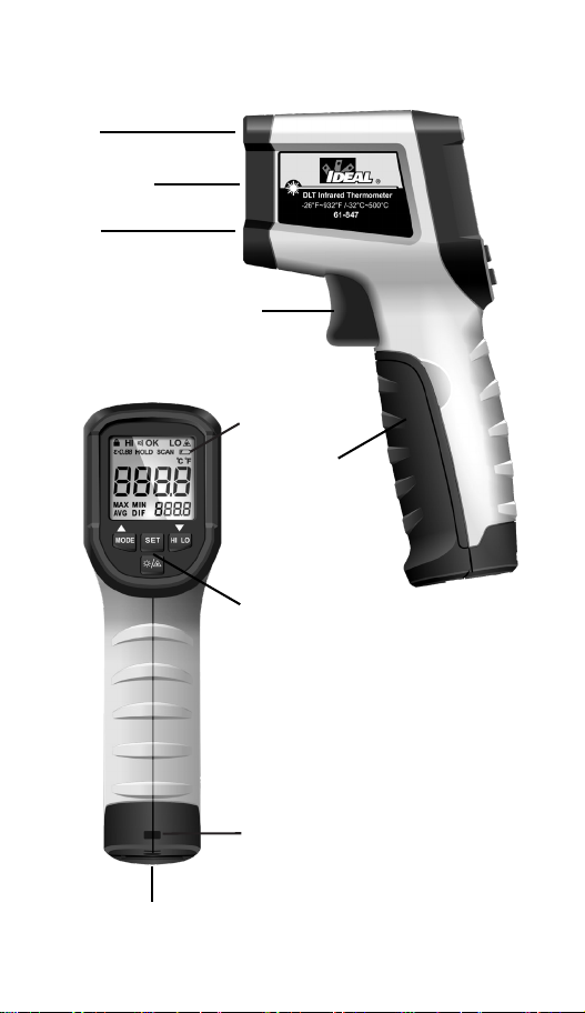
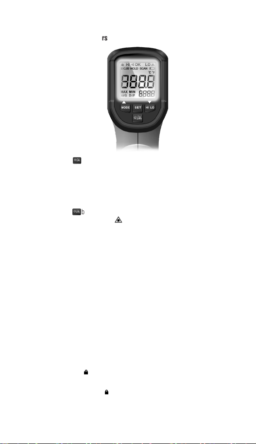
Identification and Description of Operating
Controls and Functions for the Dual Laser
Targeting Infra Red Thermometer:
1. LCD Screen
2. Function Buttons
3. Lanyard Attach Point
4. Industrial Grip Battery Cover
5. Trigger (Turns IRT On)
6. Laser Aiming Emitters
7. IR Lens
8. Standard Tripod Mount Thread
Operation
6 7
1. LCD Screen
2. Function Buttons
3. Lanyard Attach Point
4. Industrial Grip Battery Cover
5. Trigger (Turns IRT On)
6. Laser Aiming Emitters
7. IR Lens
8. Standard Tripod Mount Thread
Operation
4
1
3
6
7
2
5
6
8

8
1. HI LO/Decrease Button
2. Laser Backlight On Off Button
3. SET Button
4. Mode/Increase Button
5. LCD Display
1
2
3
4
5
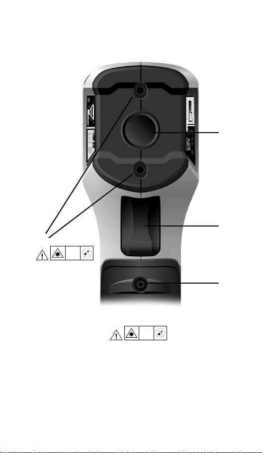
1. Laser Target Emitters
2. Infra-Red Sensor
3. Trigger
4. Battery Cover Screw
8 9
1. HI LO/Decrease Button
2. Laser Backlight On Off Button
3. SET Button
4. Mode/Increase Button
5. LCD Display
1. Laser Target Emitters
2. Infra-Red Sensor
3. Trigger
4. Battery Cover Screw
1
2
3
4
Laser
2
Laser
2

10
1. Lock Measuring Indicator
2. HI Alarm value is programmed
3. Audible Beep On or Off
4. OK indicator. Temp is within programmed limits
5. LO Alarm value is programmed
6. Laser Pointer is On or Off
7. Low Battery Indicator
8. Degrees Displayed in F or C
9. Main Display
10. Secondary Display
11. Secondary Display Legend (MODE Button)
12. Actively scanning and updating in real time.
13. HOLD the last reading in the display
14. Emissivity Setting
Display and Functions Indication Diagram
MAX MIN
AVG DIF
C F
HOLD SCAN
OK LOHI
=
3
1 2 3 4 5 6
14
13
12
7
8
9
10
11

10 11
1. Lock Measuring Indicator
2. HI Alarm value is programmed
3. Audible Beep On or Off
4. OK indicator. Temp is within programmed limits
5. LO Alarm value is programmed
6. Laser Pointer is On or Off
7. Low Battery Indicator
8. Degrees Displayed in F or C
9. Main Display
10. Secondary Display
11. Secondary Display Legend (MODE Button)
12. Actively scanning and updating in real time.
13. HOLD the last reading in the display
14. Emissivity Setting
Display and Functions Indication Diagram
6
7
8
9
10
Function Description
1 Lock Measuring Indicator
2 HI Alarm is programmed
3 Audible Beep is On or Off
4Measured Temperature is within programmed HI
and LO limits
5 LO Alarm is programmed
6 Laser Pointers are active or if blank, inactive
7 Low Battery Indicator
8 Degrees F OR C have been selected
9 Main 4 digit display
10 Secondary display of any one of MAX MIN AVG or
DIF values
11 Selected Secondary Display Value
12 Unit is in scan mode. Temp readings are constantly
updated
13 Measured Value is NOT being updated; last value
only is shown
14 User Programmed Emissivity value. Default is 0.95

12
Mode Button
Pressing the mode button after a scan (while keeping the trigger pulled)
allows you to see the Max, Min, Average, and Difference values in the
secondary display screen.
Measured Surface Outline
A single press of the trigger results in a single area temperature of the surface
outlined by the two laser dots.
Set Button
Pressing the SET button allows you to configure Hi and Low Temperature
alarms, emissivity, degrees F or C, audible alarm, auto off time, and lock
measurement setting.
Scanning
Pressing the trigger quickly places the unit in scan mode which constantly
updates the temperature reading in the display as you aim at different targets.
SCAN will appear in screen.
Operating Features
Power On
A Single Trigger pull turns the unit on and temperatures are immediately
calculated and the IRT displays the temperature of the surface it is pointed at.
(Between the two laser dots).
Taking a Reading
1. Pull and hold the trigger after aiming at the target. The SCAN icon will be
flashing indicating that the target object temperature is being measured.
The measurement result will be updated on the LCD.
2. Release the trigger, the SCAN icon disappears, and the HOLD icon
appears, indicating that the measurement has been stopped and the last
measured value is held.
Viewing the Last Measured Value
When the unit is off, a short press (less than 0.5s) of the trigger turns the
thermometer on and the last measured temperature before the last shutdown
will be displayed. Toggle to view the MAX/MIN/AVG/DIF values by short
pressing the MODE button.
Meter Operation
MAX
F
HOLD
LOHI
=
3
F
LO
HOLD
MAX
HI
=
3
Function Setting
In the HOLD interface, short press the SET button to enter the settings of high
alarm limit > low alarm limit emissivity > temperature unit > audible alarm >
lock measurement, etc. In these setting interfaces, pull the trigger or do not
operate for 10 seconds to return to the HOLD interface.
12 13
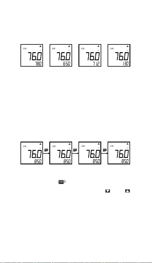
MAX/MIN/AVG/DIF Value Reading
Short press the MODE button to switch the MAX/MIN/AVG/DIF measurement
mode in tum and the temperature value of the corresponding mode will be
shown in the auxiliary display area (as shown below).
Emissivity Setting
In the HOLD interface, short press the SET button until emissivity setting is
displayed. Short press the button to quickly select the preset emissivity
value (P1-P5). If no desired value among the preset values, select any
value closest to the emissivity, and adjust it by pressing the button or
button. Add or subtract 0.01 each time by short press, and add or subtract 0.1
per second by long press.
(see table on page 16)
Operating Features
Power On
A Single Trigger pull turns the unit on and temperatures are immediately
calculated and the IRT displays the temperature of the surface it is pointed at.
(Between the two laser dots).
Taking a Reading
1. Pull and hold the trigger after aiming at the target. The SCAN icon will be
flashing indicating that the target object temperature is being measured.
The measurement result will be updated on the LCD.
2. Release the trigger, the SCAN icon disappears, and the HOLD icon
appears, indicating that the measurement has been stopped and the last
measured value is held.
Viewing the Last Measured Value
When the unit is off, a short press (less than 0.5s) of the trigger turns the
thermometer on and the last measured temperature before the last shutdown
will be displayed. Toggle to view the MAX/MIN/AVG/DIF values by short
pressing the MODE button.
MAX
F
HOLD
LOHI
=
3
F
LO
HOLD
OK
MIN
HI
=
3
F
LO
HOLD
AVG
HI
=
3
F
LO
HOLD
OK
DIF
HI
=
3
High/Low Temperature Alarm On/Off
Short press the HI/LO button to turn the high/low limit alarm function on and
off in sequence.
When HI limit alarm function is turned on and the measured temperature value
is higher than the set high alarm limit, the HI indicator flashes. If the audible
alarm function has been turned on, the buzzer will beep.
When LO limit alarm function is turned on and the measured temperature
value is lower than the set low alarm limit, the blue LED and LO indicator
flashes. If the audible alarm function has been turned on, the buzzer will beep.
When HI/LO limit alarm function is turned on and the measured temperature
value is within the high and low alarm limit range, no HI or LO icon means
that the temperature is within range.
F
LO
HOLD
MAX
HI
=
3
F
LO
HOLD
MAX
=
3
F
LO
HOLD
MAX
HI
=
3
F
LO
HOLD
MAX
=
3
14
Temperature Unit Setting
In the HOLD interface, short press the SET button until temperature unit
setting is displayed, and switch between °C and °F by pressing the button
or button.
Audible Alarm Setting
In the HOLD interface, short press the SET button until audible alarm setting
is displayed, and turn on/off the audible alarm by pressing the
button or button.
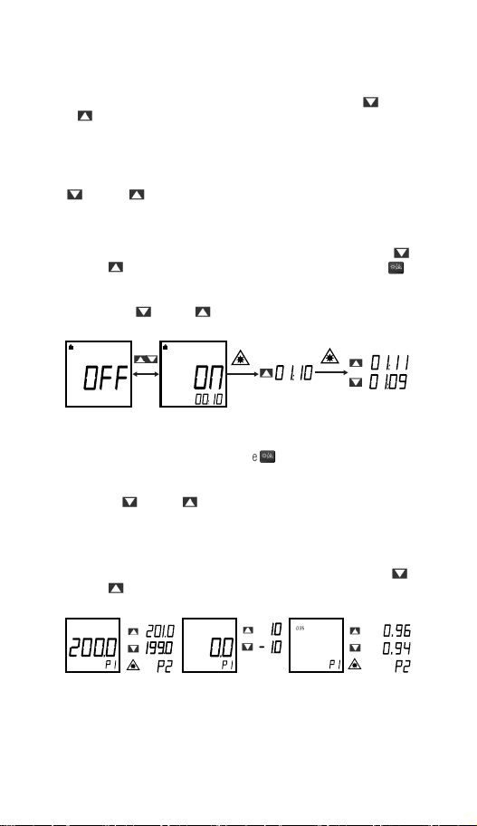
Lock Measurement Setting
In the HOLD interface, short press the SET button until lock measurement
setting is displayed, and turn on/off the lock measurement by pressing the
button or button. When the lock measurement is turned on, press the
button to perform the timing setting “00:00” for the lock measurement. At this
time, the selected time position flashes, and the time value can be adjusted
by pressing the button or button. Set timing to “_ _:_ _” to turn off
timing function.
High Alarm Limit Setting
In the HOLD interface, short press the SET button once to enter the high
alarm limit setting interface. Short press the button to quickly select the
preset high alarm limit value (P1-P5). If there is no desired value among the
preset values, select any value closest to the high alarm limit, and adjust it by
pressing the button or button. Add or subtract 1 each time by short
press, and add or subtract 10 per second by long press. (see Figure 1)
Low Alarm Limit Setting
In the HOLD interface, short press the SET button twice to enter the low alarm
limit setting interface, and adjust the low alarm limit value by pressing the
button or button. Add or subtract 1 each time by short press, and add or
subtract 10 per second by long press. (see Figure 2)
HI
LO
=
3
=
3
=
3
Backlight/Laser Pointers
14 15
Laser Indication Function On/Off
Short press the button to turn on/off the laser indication function. When
it is turned on, the laser indicator will be displayed on the LCD, and the
laser will accurately outline the area you are measuring during temperature
measurement.
NOTE: Please follow the laser precautions when the laser is turned on to
avoid damage to human or animal eyes.
Short press the button on the meter to turn the backlight on and off.
The white backlight will remain illuminated for about 5 minutes before
automatically turning off to conserve battery power. Or turn the lights off by
pressing and holding the button again. A long press >2 seconds will turn the
laser on or off.
Backlight/Laser Pointers
Lock Measurement
Description:
• In the lock measurement function setting interface, the lock measurement
time (1 minute to 5 hours) can be set. Refer to Lock Measurement Setting
for details.
• After setting time, the measurement starts after the activation of the lock
function. When the set time is reached, the thermometer will automatically
power off and save the last measured value.
• You can view the measured values by short pressing (less than 0.5s) the
trigger (NOTE: The measured values will be cleared by a long press). This
operation is applicable to processes that require regular monitoring of
temperature. If no timing is needed, leave them blank.
Operation:
1. When the lock measurement function is turned on, short press the trigger
to enable it. The icon will appear on the thermometer screen and the
SCAN icon will flash. The thermometer will continuously measure the
target temperature.
2. Pull the trigger again, the and SCAN icons disappear, and the HOLD
icon appears. The thermometer stops the measurement and holds the last
measured value.
MAX MIN
AVG DIF
C F
HOLD SCAN
OK LOHI
=
3
MAX MIN
AVG DIF
C F
HOLD SCAN
OK LOHI
=
3

16
Auto Power Off
In the HOLD mode, if there is no operation for 15 seconds, the thermometer
will automatically power off and save the currently held measurement.
NOTE: During measurement, it is best to ensure that the measured target
diameter is twice the spot size (S) of the thermometer, and then determine the
test distance (D) according to the D:S diagram (refer to D:S part).
For example, if you use the 61-847 to measure the temperature of an object
with a diameter of about 4” (10cm), then according to the above, the spot
size (S) of the thermometer should be about 2” (5cm) for highest accuracy,
and according to the D:S diagram, the measured distance (D) is about 24”
(60 cm).
Emissivity
Emissivity is the term used to describe the efficiency with which a particular
surface emits Infra-Red Radiation IN THE WAVELENGTHS that are detectable
by the sensor in the IR Thermometer. Its sensitivity is in the 8 to 14-micron
wavelength range. To be sure, a hot mass will radiate IR in many different
wavelengths, but the sensing technology employed in this type of instrument
has a narrow bandwidth. Some materials, such as electrical tape, human
skin, certain types of paints are efficient emitters in these Wavelengths.
Others such as aluminum, brass, and gold are inefficient emitters, again, IN
THESE WAVELENGTHS. Heat a bar of gold to 200 degrees and try to read
its temperature and it will appear cold. Cover it in electrical tape, and scan
the tape, and the temperature will be much higher and much more accurate.
Please remember this when making measurements of certain objects. This can
and does greatly affect the accuracy of the readings. This is why you can set
the emissivity value in the meter.
Human Skin 0.98
Smooth Ice 0.96
Carbon Candle Soot 0.95
Oil Based Paint 0.94
White Bond Paper 0.93
Snow 0.85
Stainless Steel 0.85
Oxidized Copper 0.78
Rust 0.71
Cast Iron 0.64
Buffed Stainless Steel 0.16
Polished Brass 0.03
16 17
Emissivity
Emissivity is the term used to describe the efficiency with which a particular
surface emits Infra-Red Radiation IN THE WAVELENGTHS that are detectable
by the sensor in the IR Thermometer. Its sensitivity is in the 8 to 14-micron
wavelength range. To be sure, a hot mass will radiate IR in many different
wavelengths, but the sensing technology employed in this type of instrument
has a narrow bandwidth. Some materials, such as electrical tape, human
skin, certain types of paints are efficient emitters in these Wavelengths.
Others such as aluminum, brass, and gold are inefficient emitters, again, IN
THESE WAVELENGTHS. Heat a bar of gold to 200 degrees and try to read
its temperature and it will appear cold. Cover it in electrical tape, and scan
the tape, and the temperature will be much higher and much more accurate.
Please remember this when making measurements of certain objects. This can
and does greatly affect the accuracy of the readings. This is why you can set
the emissivity value in the meter.
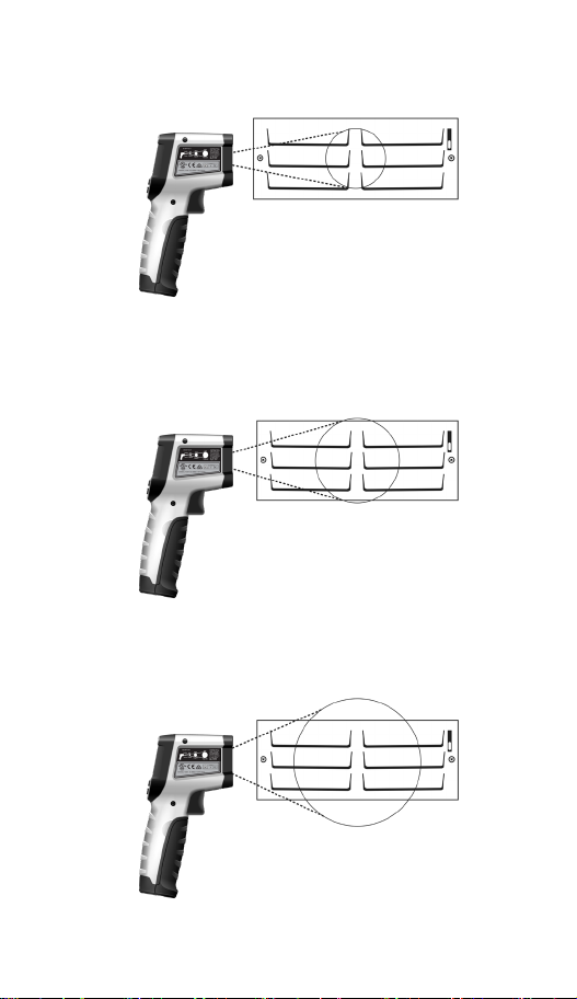
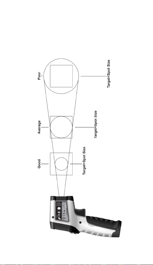
Best Accuracy Coverage
Average Accuracy Coverage
Poor Accuracy Coverage

18
Spot Size to Distance
The measured surface area can represent a cone emanating out from the
sensor. The further the distance to the surface, the larger the area that will
influence temperature measurements. It is important that when it safe to
do so, get as close as possible to the target, using the dual lasers to define
the perimeter of an imaginary circle. This will increase the accuracy of the
displayed temperature. Also, make measurements at 90 degrees to the surface
as angular measurements are less accurate. (Reference diagram below)
Field of View
18 19
Spot Size to Distance Field of View
Make sure that the measured target is larger than the spot size. The smaller
the target, the closer the test distance should be (please refer to D:S for the
spot size at different distances). To obtain the optimum measurement result,
it is recommended that the target being measured is 2 times larger than the
spot size.

20
Button Response Default Function Operation
MAX MIN AVG DIFF Last Selection Short press toggles sequentially through the 4 selections
HI, LO Alarms, Emissivity,
Degrees F or C, Audible,
Auto Power Off delay.
Lock Measurement
Setting
HI Alarm Setting
When HI or LO appear, press the up or down arrow keys to increase or decrease the alarm
levels. When the emissivity icon appears, press the up or down arrows to increase or decrease
that value. NOTE: 0.95 is a good general purpose setting for most materials. When F or C
appear, press either arrow key to switch to the other scale. When the speaker icon appears, press
either arrow to select sound to be on or off. A beep will sound when you select sound to be on.
When the lock icon appears, using the arrow buttons select the minutes and seconds before the
unit auto powers off. Use the ‘Backlight/Laser’ button to toggle between minutes and seconds.
HI LO Last Selection Press to select HI or LO alarm indication. OK appears if temp is within alarm limits.
Backlight or Laser On
or Off Last Selection Short press toggles the Backlight On or Off. Long press toggles the laser pointers On or Off.
Increases or decreases
variable values. None Short Press for small increments or hold for long increments of selected value.
Lock Measurement Indicator
Buzz Indicator
Temperature Measurement
Alarm Indicator
Low Battery Indicator
Temperature Measurement
Indicator
Temperature Hold Indicator
Temperature Unit Indicator
Main Display of the Measured
Temperature
Auxillary Display of the
Measured Temperature
Emissivity Indication
Laser Indicator
Measurement Mode Indication
MAX MIN
AVG DIF
C F
HOLD SCAN
OK LOHI
=
3
MAX MIN
AVG DIF
C F
HOLD SCAN
OK LOHI
=
3
MAX MIN
AVG DIF
C F
HOLD SCAN
OK LOHI
=
3
MAX MIN
AVG DIF
C F
HOLD SCAN
OK LOHI
=
3
MAX MIN
AVG DIF
C F
HOLD SCAN
OK LOHI
=
3
MAX MIN
AVG DIF
C F
HOLD SCAN
OK LOHI
=
3
MAX MIN
AVG DIF
C F
HOLD SCAN
OK LOHI
=
3
MAX MIN
AVG DIF
C F
HOLD SCAN
OK LOHI
=
3
MAX MIN
AVG DIF
C F
HOLD SCAN
OK LOHI
=
3
MAX MIN
AVG DIF
C F
HOLD SCAN
OK LOHI
=
3
MAX MIN
AVG DIF
C F
HOLD SCAN
OK LOHI
=
3
MAX MIN
AVG DIF
C F
HOLD SCAN
OK LOHI
=
3
MAX MIN
AVG DIF
C F
HOLD SCAN
OK LOHI
=
3
MAX MIN
AVG DIF
C F
HOLD SCAN
OK LOHI
=
3
MAX MIN
AVG DIF
C F
HOLD SCAN
OK LOHI
=
3
Functions Indications Table
Functions Operations Table
Table of contents
Languages:
Other IDEAL Thermometer manuals


