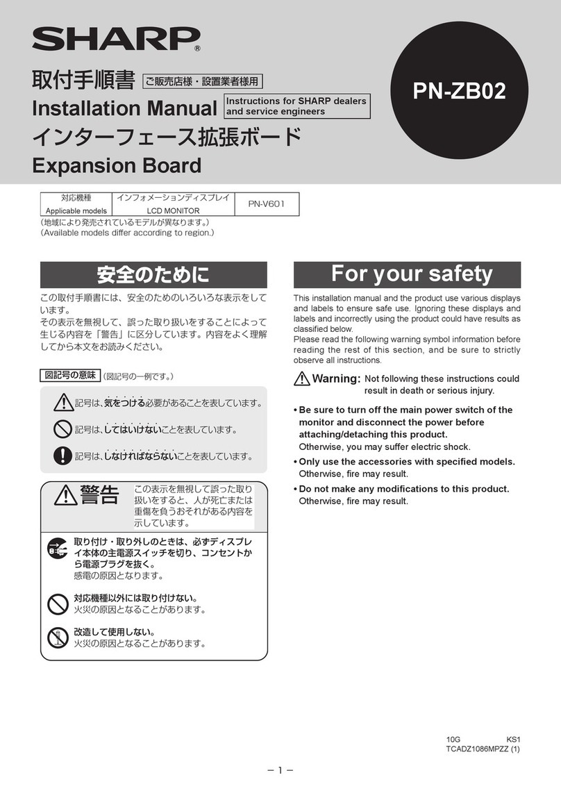
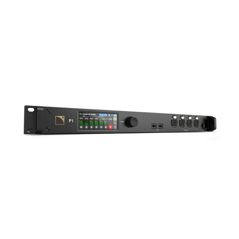
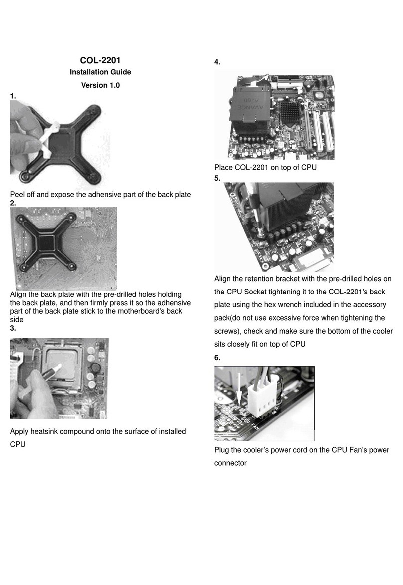
IDEATEC PPS-TWIN User manual

IDEATEC S.A. - Z.I. de Noville-les-Bois - rue Léopold Génicot 19A - 5380 Fernelmont, Belgium - Tel: +32(0)81 42 00 10 - E-mail: [email protected]
User Guide PPS-TWIN V1.0 - Module V1.7
Page 1
AIR HORN EMULATOR
TONE INCLUDED
Compatible with
for Windows
User Guide
Due to technological advances, the manufacturer reserves the right
to modify the characteristics of this product without notice
2x100W SIREN

IDEATEC S.A. - Z.I. de Noville-les-Bois - rue Léopold Génicot 19A - 5380 Fernelmont, Belgium - Tel: +32(0)81 42 00 10 - E-mail: [email protected]
User Guide PPS-TWIN V1.0 - Module V1.7
1.
Page 2
Safety and precautions
The safety of future users of this product depends on your installation. Therefore, it is critical that you read, understand, and follow all
instructions contained in this installation guide.
Some instructions and precautions that must be applied are listed below (see page 3 too) :
ITo install this equipment correctly, it is essential to have the understanding and the technical skills for the installation of automobile electronics.
IPlace this installation guide in a safe place and refer to it when necessary and for each installation. This manual must be delivered to the end
user.
IBefore wiring, disconnect the cable from the negative battery terminal. Failure to do so may result in electric shock or injury due to electrical
shorts. Connect again the cable on the negative battery terminal once the installation is completely finished.
IUse only in cars with a +12 or +24 volt negative ground (check with your car manufacturer if you are not sure). Failure to do so may result in fire,
etc.
IThe IDEATEC system must be powered by a DC voltage between + 10V and +30V. Use of AC voltage or DC voltage greater than + 30V can
result in property damage, fire hazard, serious injury or fatal injury to yourself and / or others.
INever install any devices or accessories inside the airbag deployment area. Such installation might reduce the effectiveness of the airbag or
prevent it from being deployed. It can also potentially damage or dislodge the device, causing serious or fatal injuries.
IInstallation of the equipment must comply with local and national electrical codes.
IIt is imperative to dimension correctly all wires installed and connected to the positive battery terminal (see the chart on page 3) and protected by
a proper fuse placed as close as possible to the battery.
ITo ensure a correct operation of the device installed, it is necessary to make a perfect connection to the negative terminal. The negative output of
the device must be connected to the negative terminal of the battery as directly as possible. The same applies to any elements controlled by the
installed device.
IDo not allow cables to become entangled in surrounding objects. Arrange wiring and cables in compliance with the manual to prevent obstructions
when driving. Cables or wiring that obstruct or hang up on places such as the steering wheel, shift lever, brake pedals, etc. can be extremely
hazardous.
IPosition the cables in such a way that they can never be damaged by vehicle vibrations or by impact (metal edge in direct proximity, mechanical
stress on the cable, etc.). Also make sure that all users of the vehicle can never damage the cables directly or indirectly.
IMake sure that none of the vehicle's original controls are affected by the installed device.
IIf you need to drill a hole in the dashboard, make sure that both sides are completely free to avoid damaging the vehicle.
IAlways install the console or the central unit in a ventilated area, and never close to a heat source. This area must also be protected against dust
and moisture.
IPlease remind, any use of a relay connected to an output of the PPS-TWIN (positive or negative) must respect the usual precautions, namely the
installation of a freewheeling diode at least. Be careful to respect the polarity of the diode when connecting it.
In addition, if the current flowing through the relay contact is very high, opening the contact can cause sparks inside the relay and cause
disturbances in the wire harness. It is recommended in this case to add a capacitor absorbing the effects of sparks. Be careful to respect the
polarity of the capacitor when connecting it (see the diagram below). The capacitor must be able to support a minimum voltage of 50V.
IIf you have problems, do not attempt to repair the unit yourself. Return it to your IDEATEC dealer for servicing.
+
POSITIVE OUTPUT
RELAY
FREEWHEELING
DIODE
RELAY
FREEWHEELING
DIODE
NEGATIVE OUTPUT
OR
POSITIVE OUTPUT
RELAY
FREEWHEELING
DIODE
+
+
-
LOAD

IDEATEC S.A. - Z.I. de Noville-les-Bois - rue Léopold Génicot 19A - 5380 Fernelmont, Belgium - Tel: +32(0)81 42 00 10 - E-mail: [email protected]
User Guide PPS-TWIN V1.0 - Module V1.7
1.
2.
Page 3
0.34
22
X
X
X
X
X
X
X
X
X
X
X
X
X
X
X
X X X
0.5
20
X
X
X
X
X
X
X
X
X
X
X
X
X
X
X
X X X
0.75
18
X
X
X
X
X
X
X
X
X
X
X
X
X
X
X
X X X
1.5
16
X
X
X
X
X
X
X
X
X
X
X
X
X
X
X
X X X
2.5
14
1.2m
4 Feet
1m
3.5 Feet
0.9m
3 Feet
0.9m
3 Feet
0.9m
3 Feet
X
X
X
X
X
X X X
4
12
1.8m
6 Feet
1.7m
5.5 Feet
1.5m
5 Feet
1.5m
5 Feet
1.3m
4.5 Feet
1.2m
4 Feet
1.2m
4 Feet
1m
3.5 Feet 1m 3.5 Feet
6
10
3.0m
10 Feet
2.7m
9 Feet
2.4m
8 Feet
2.2m
7.5 Feet
2.1m
7 Feet
2m
6.5 Feet
1.8m
6 Feet
1.8m
6 Feet 1.6m 5.5 Feet
10
8
4.7m
15.5 Feet
4.2m
14 Feet
4m
13 Feet
3.6m
12 Feet
3.3m
11 Feet
3.2m
10.5 Feet
3m
10 Feet
2.7m
9 Feet 2.5m 8.5 Feet
16
6
7.6m
25 Feet
6.8m
22.5 Feet
6.2m
20.5 Feet
5.8m
19 Feet
5.3m
17.5 Feet
5m
16.5 Feet
4.7m
15.5 Feet
4.4m
14.5 Feet 4.2m 14 Feet
25
4
12m
39.5 Feet
11m
36 Feet
10m
33 Feet
9.2m
30.5 Feet
8.5m
28 Feet
8m
26.5 Feet
7.4m
24.5 Feet
7m
23 Feet 6.7m 22 Feet
35
2
19.2m
63 Feet
17.3m
57 Feet
16m
52.5 Feet
14.7m
48.5 Feet
13.7m
45 Feet
12.8m
42 Feet
11.8m
39 Feet
11.2m
37 Feet 10.6m 35 Feet
50A 55A 60A 65A 70A 75A 80A 85A 90A
0.34
22
1.8m
6 Feet
0.9m
3 Feet
X
X
X
X
X
X
X
X
X
X
X
X X X
0.5
20
2.9m
9.5 Feet
1.5m
5 Feet
0.9m
3 Feet
X
X
X
X
X
X
X
X
X
X X X
0.75
18
4.5m
15 Feet
2.2m
7.5 Feet
1.5m
5 Feet
1.2m
4 Feet
0.9m
3 Feet
X
X
X
X
X
X X X
1.5
16
7.5m
24.5 Feet
3.5m
12 Feet
2.4m
8 Feet
1.8m
6 Feet
1.5m
5 Feet
1.2m
4 Feet
1m
3.5 Feet
0.9m
3 Feet X X
2.5
14
12m
39 Feet
6m
19.5 Feet
4m
13 Feet
2.8m
9.5 Feet
2.5m
8 Feet
2m
6.5 Feet
1.6m
5.5 Feet
1.5m
5 Feet 1.3m 4.5 Feet
4
12
20m
62 Feet
9.5m
31 Feet
6m
20.5 Feet
4.7m
15.5 Feet
3.8m
12.5 Feet
3.2m
10.5 Feet
2.7m
9 Feet
2.3m
7.5 Feet 2.1m 7 Feet
6
10
30m
98 Feet
15m
49 Feet
10m
32.5 Feet
7.5m
24.5 Feet
6m
19.5 Feet
5m
16.5 Feet
4.2m
14 Feet
3.8m
12.5 Feet 3.3m 11 Feet
10
8
48m
156 Feet
24m
78 Feet
16m
52 Feet
11.8m
39 Feet
9.4m
31 Feet
8m
26 Feet
6.8m
22.5 Feet
5.9m
19.5 Feet 5.3m 17.5 Feet
16
6
75m
248 Feet
37m
124 Feet
25m
82.5 Feet
18.8m
62 Feet
15m
49.5 Feet
12.6m
41.5 Feet
10m
35.5 Feet
9.4m
31 Feet 8.3m 27.5 Feet
25
4
120m
395 Feet
60m
197 Feet
40m
131 Feet
30m
98.5 Feet
24m
79 Feet
20m
66 Feet
17m
56.5 Feet
15m
49.5 Feet 13.4m 44 Feet
35
2
190m
629 Feet
95m
314 Feet
63m
209 Feet
47m
157 Feet
38m
125 Feet
31m
104 Feet
27m
89.5 Feet
2.9m
78.5 Feet 21m 69.5 Feet
5A 10A 15A 20A 25A 30A 35A 40A 45A
X
Fig.1
FILS
mm² AWG
FILS
mm² AWG
MAXIMUM AUTHORISED CURRENT IN THE WIRES
MAXIMUM AUTHORISED CURRENT IN THE WIRES
ABACUS FOR THE DIMENSIONING OF ELECTRIC WIRES
It is essential and mandatory to dimension electrical wires correctly according to the currents used and the length of the wires. Failure to dimension
correctly may cause fire inside the vehicle. The product is equipped with static relay outputs only. The use of static relays has several advantages,
among which the suppression of external fuses.
The cable connected to the + terminal of the PPS-TWIN must be protected by a fuse calculated on the basis of the total current consumed according
to the configuration (maximum 40A). Its section must be sufficient to support this current.
To fix the wire size, you must follow three essential precautions:
R Know or determine the maximum current consumed at each static output.
R Setup each static output used to limit the maximum current from 0,5 to 10A thanks to the software provided by IDEATEC S.A..
R Select the wire gauge according to its length and the current absorbed using the chart below :
Dimensioning of electric wires
Safety and precautions (continued)
= Insufficient
ICheck that any inductive load connected to the PPS-TWIN is equipped with an overvoltage protection diode (see diagram below) which absorbs
reverse voltage peak that can be destructive. Inductive load can be motor, water pump, vacuum cleaner, fan, contactor, etc. In case of doubt, it is
imperative to consult your reseller or Ideatec. If free output is available to the user (+ 12V socket, cigarette lighter socket, etc.), the overvoltage
protection diode must be fitted. The diode must have a reverse avalanche voltage threshold (Vrm) equal to or greater than 33V, for example diode
BZW50-33. Any inverter type load connection is strictly prohibited.
IFailure to follow safety guidelines and instructions may cause material damages, injuries, or death to you and/or to others.
IAll IDEATEC metal cases must be grounded correctly to the negative battery. Never defeat the ground conductor or operate the equipment in the
absence of a suitably installed ground conductor. Ideatec provides a kit REF.P0035F0034 to make this connection. The connection must be made
on one of the flanges of the Ideatec system as shown in figure 1. The tooth washers must be positioned on either side of the terminal as shown in
figure 1. The terminal provided allows a cable cross-section of 4 mm² to 6mm³, however Ideatec SA requires the placement of a 6mm² cable with
a maximum length of 50cm.
IDEATEC S.A. assumes no liability and give the right to refuse any warranty if one or more of the
recommendations on page 2 and 3 are not being followed.
POWER POSITIVE OUTPUT
POWER
SUPPLY
INPUT
INDUCTIVE
LOAD
OVERVOLTAGE
PROTECTION
DIODE
+

IDEATEC S.A. - Z.I. de Noville-les-Bois - rue Léopold Génicot 19A - 5380 Fernelmont, Belgium - Tel: +32(0)81 42 00 10 - E-mail: [email protected]
User Guide PPS-TWIN V1.0 - Module V1.7
3.
Page 4
1
4
10
7
1(+ IGNITION)
2
3
4
5
6
7
8
5
3
14
11
26
18
17
16
13
14
11
2
2
1
12
3
4
5
678
1
2
3
4
5
6
7
8
9
10
11
12
13
14
15
16
17
18
1
2
1411
2
POSITIVE OUTPUT 1
POSITIVE OUTPUT 2
POSITIVE OUTPUT 3
POSITIVE OUTPUT 4
NEGATIVE OUTPUT 1
SPEAKER A
SPEAKER B
INPUTS
CONTROL
POWER
SUPPLY
INPUTS
RELAY COMMON
RELAY NORMAL CLOSE
RELAY NORMAL OPEN
CANBUS - H
CANBUS - L
Switch 1
Switch 2
OFF
ON
OFF
ON
Canbus termination disable
Canbus termination enable
Input 1 for ignition
Forced ignition
Product description
3.1 Basic Hardware Description
The description here below shows the inputs and outputs of the PPS-TWIN.
The siren PPS-TWIN provides 4 positive power outputs and 1 negative output for equipments.
The changeover relay output is made to control special equipment or manage special function like vehicle horn cut off.
Tne canbus connexion and the 8 inputs are available and configurable to control all the functions of the PPS-TWIN.

IDEATEC S.A. - Z.I. de Noville-les-Bois - rue Léopold Génicot 19A - 5380 Fernelmont, Belgium - Tel: +32(0)81 42 00 10 - E-mail: [email protected]
User Guide PPS-TWIN V1.0 - Module V1.7
3.
Page 5
1
2
3
4
5
6
7
8
9
1
2
3
4
5
6
1234
*
*
*
*
MK-10
Monitoring
Product description (continued)
3.2 Control for PPS-TWIN
*available soon
OR
OR
OR
It is only possible to connect a single FSP to
the PPS-TWIN. It is also not possible to use an
FSP console in combination with the PA MK-10
console.
USB connector for SpeedFitter configuration
Several control consoles are compatible with the PPS-TWIN.
The PA microphone is PPS-TWIN compatible.
The PA MK-10 microphone is equipped with 10 keys to control the PPS-TWIN siren and its outputs. It will be available
in a future phase of the PPS-TWIN like the FSP consoles.

IDEATEC S.A. - Z.I. de Noville-les-Bois - rue Léopold Génicot 19A - 5380 Fernelmont, Belgium - Tel: +32(0)81 42 00 10 - E-mail: [email protected]
User Guide PPS-TWIN V1.0 - Module V1.7 Page 6
03
03'
4.
04
02
01
5m
01
02
03
Elements identification
4.1 PPS-TWIN Module - REF.P0050F0117
DESCRIPTION
PPS-TWIN siren module
Kit Connector Minifit 8p + 10x crimp terminals
Kit Connector TE 18p + 18x crimp terminals
Kit Connector Minifit 2p + 3x crimp terminals
TE 18p harness 50cm
P/N
P0050F117
P0035F0007
P0035F0042
P0035F0019
P0020F0135
Item
1
2
3
4
3'
Qty
1
1
1
1
1
Option harness for TE connector
DESCRIPTION
PA Microphone
IC-Adaptor model A RJ45/RJ45
FTP Bus cable black 5m lenght
P/N
P0040F0014
P0040F0049
P0020F0027/FTP
Item
1
2
3
Qty
1
1
1
4.2 Micro PA - REF.P0050F0003/V2

IDEATEC S.A. - Z.I. de Noville-les-Bois - rue Léopold Génicot 19A - 5380 Fernelmont, Belgium - Tel: +32(0)81 42 00 10 - E-mail: [email protected]
User Guide PPS-TWIN V1.0 - Module V1.7 Page 7
4.
± 60 cm
02
03
01
05
06
04
07
*
*available soon
In order to ensure perfect operation, only
RJ45/RJ45 interfaces assembled and
supplied by the manufacturer are accepted.
Otherwise, unless authorised in writing, the
manufacturer will not accept any warranties
or liability on the equipment installed.
4.3 Handheld PA Console MK-10 - REF.P0050F0005
Elements identification (continued)
Item
1
2
3
4
5
6
7
Qty
1
1
1
1
1
1
1
DESCRIPTION
PA MK-10 Console
Foot adaptor
Multi-directional foot mouting option
FTP Bus cable black 5m lenght
IC-Adaptor model A RJ45/RJ45
Spiral Bus cable
Pictogram set
P/N
P0050F0005
A1000B0084
P0039F0003
P0020F0027/FTP
P0040F0049
P0010A0088
A6800B0071

IDEATEC S.A. - Z.I. de Noville-les-Bois - rue Léopold Génicot 19A - 5380 Fernelmont, Belgium - Tel: +32(0)81 42 00 10 - E-mail: [email protected]
User Guide PPS-TWIN V1.0 - Module V1.7 Page 8
4.
L
18
1
10+3
1
1
1-968857-1
8-968974-1
649 005 137 22
649 002 113 322
649 008 113 322
The TE and Würth connectors are necessary to connect inputs/outputs of the PPS-TWIN.
Their contacts must be crimped with a suitable tool (see references below).
4.5 Connectors & Crimp contacts
Tool References
Pin Extractor
1579007-1
Qty
TE Connector Crimp Terminal
AWG 14-16
Crimp Tool
1976143-1
With Die Assembly
539727-2
Description TE/Wurtz Reference
TE Connector 18P.
Würth Connector Crimp Terminal
AWG 16
Würth Connector 2P.
Würth Connector 8P.
.
Crimp Tool
600 001
With Die Assembly
600 420 420 001
Pin Extractor
600 649
4.4 2x RJ45 Bus Cable - Option
In order to ensure perfect operation, only BUS cables assembled and supplied by the manufacturer
are accepted. Otherwise, unless authorised in writing, the manufacturer will not accept any
warranty or liability on the equipment installed.
Standard or special option order :
Length = 1 meter - P/N : P0020F0042
Length = 5 meters - P/N : P0020F0027/FTP
Length = 6 meters - P/N : P0020F0043
Length = 8 meters - P/N : P0020F0028
Length = 10 meters - P/N : P0020F0029
Length = 15 meters - P/N : P0020F0044
Right Connector
Length = 5 meters - P/N : P0020F0097
Length = 8 meters - P/N : P0020F0098
Elements identification (continued)
*original cable provided with microphone PA,
console PA handheld MK-10 or FSP console

IDEATEC S.A. - Z.I. de Noville-les-Bois - rue Léopold Génicot 19A - 5380 Fernelmont, Belgium - Tel: +32(0)81 42 00 10 - E-mail: [email protected]
User Guide PPS-TWIN V1.0 - Module V1.7 Page 9
4.
04
02
01
02
01
02
**available soon
Elements identification (continued)
In order to ensure perfect operation, only screws supplied by the manufacturer are accepted.
Otherwise, unless authorised in writing, the manufacturer will not accept any warranty or liability on
the equipment installed.
P/N
P0040F0073
P0035F0017
A1000B0154
P0039F0007
DESCRIPTION
FSP-4K Console
Kit 2x screw M3,9x16
FSP-4K green cover
FSP Pictogram + Color Kit
Item
1
2
3
4
Qty
1
1
1
1
4.6 FSP-4K Console - REF.P0050F0106
P/N
A1000B0160
P0035F0027
DESCRIPTION
FSP-4K housing
Fixing kit FSP-4K
Item
1
2
Qty
1
1
iProvided with 5m BUS cable - REF.P0020F0027/FTP
4.6.1 Wall mounting by default
4.6.2 Housing option - REF.P0039F0008

IDEATEC S.A. - Z.I. de Noville-les-Bois - rue Léopold Génicot 19A - 5380 Fernelmont, Belgium - Tel: +32(0)81 42 00 10 - E-mail: [email protected]
User Guide PPS-TWIN V1.0 - Module V1.7 Page 10
4.
04
02
01
03
03
03
03
03
03
03
02
01
01
**available soon
In order to ensure perfect operation, only screws supplied by the manufacturer are accepted.
Otherwise, unless authorised in writing, the manufacturer will not accept any warranty or liability on
the equipment installed.
P/N
P0040F0074
P0035F0018
A1000B0155
P0039F0007
DESCRIPTION
FSP-6K Console
Kit 4x screw M3,5x16
FSP-6K green cover
FSP Pictogram + Color Kit
Item
1
2
3
4
Qty
1
1
1
1
Elements identification (continued)
4.7 FSP-6K Console - REF.P0050F0107
iProvided with 5m BUS cable - REF.P0020F0027/FTP
4.7.1 Wall mounting by default
4.7.2 Housing option - REF.P0039F0009
P/N
A1000B0161
P0035F0026
P0039F0003
DESCRIPTION
FSP-6K housing
Fixing kit FSP-6K
Foot mounting kit
Item
1
2
3
Qty
1
1
1

IDEATEC S.A. - Z.I. de Noville-les-Bois - rue Léopold Génicot 19A - 5380 Fernelmont, Belgium - Tel: +32(0)81 42 00 10 - E-mail: [email protected]
User Guide PPS-TWIN V1.0 - Module V1.7 Page 11
4.
04
03
03
03
03
03
03
03
02
01
01
02
01
**available soon
Elements identification (continued)
In order to ensure perfect operation, only screws supplied by the manufacturer are accepted.
Otherwise, unless authorised in writing, the manufacturer will not accept any warranty or liability on
the equipment installed.
P/N
P0040F0075
P0035F0018
A1000B0156
P0039F0007
DESCRIPTION
FSP-9K Console
Kit 4x screw M3,5x16
FSP-9K green cover
FSP Pictogram + Color Kit
Item
1
2
3
4
Qty
1
1
1
1
4.8 FSP-9K Console - REF.P0050F0108
iProvided with 5m BUS cable - REF.P0020F0027/FTP
4.8.1 Wall mounting by default
4.8.2 Housing option - REF.P0039F0010
P/N
A1000B0162
P0035F0026
P0039F0003
DESCRIPTION
FSP-9K housing
Fixing kit FSP-9K
Foot mounting kit
Item
1
2
3
Qty
1
1
1

IDEATEC S.A. - Z.I. de Noville-les-Bois - rue Léopold Génicot 19A - 5380 Fernelmont, Belgium - Tel: +32(0)81 42 00 10 - E-mail: [email protected]
User Guide PPS-TWIN V1.0 - Module V1.7 Page 12
5.
*
*available soon
Elements installation
Use only screws, nuts, and washers provided
by the manufacturer.
Using other, longer screws in the back of the
console may seriously damage its internal
parts.
The manufacturer cannot assure any
warranties or accept liability if other fixing
elements or screw, nuts, and washers are
used to install the console.
Ü Preassemble the console without blocking the 2 hexagonal head screws
Ü Choose the best place to install the console on the dashboard.
Ü Locate and note the 6 fixation holes at the base of the foot (page 18).
Ü Fix the base and position the console perfectly.
Ü Block the 2 hexagonal head screws.
Ü Attach the cover to the back of the foot with the screw provided.
Ü Place the small black cap on the head of the screw on the back.
5.1.1 Console mounting
The safety of future users of this product depends on your installation. Therefore, it is critical that
you read, understand, and follow all instructions contained in this installation guide.
ÜYou can configure the keys on the keypad using the set of 88 pictograms provided.
ÜTo ensure good adherence of the pictogram to the cavity on each key, avoid touching the adhesive
part of the pictograms and the key cavities with your fingers.
5.1.2 Pictograms fixing
5.1 MK-10 Console Installation

IDEATEC S.A. - Z.I. de Noville-les-Bois - rue Léopold Génicot 19A - 5380 Fernelmont, Belgium - Tel: +32(0)81 42 00 10 - E-mail: [email protected]
User Guide PPS-TWIN V1.0 - Module V1.7 Page 13
5.
a
FSP-4K FSP-6K FSP-9K
Fig.2
Fig.1
*available soon
5.2 FSP-4K, FSP-6K and FSP-9K Installation
5.2.1 Pictograms
ATTENTION: The force applied to tighten the screw must never be higher than 6Nm. The manufacturer
can not be able to provide repairs if the MAX 6Nm tightening force is exceeded.
To ensure good adherence of
the pictogram on each key,
avoid touching the adhesive
part of the pictograms and the
key surface with your fingers.
The keys of the FSP consoles are configurable for the pictograms thanks to the stickers provided. The backlight is
white by default but you can change it thanks to the color stickers provided with the console.
To access to the keys, you have first to dismantle the front panel to release the protection membrane (Fig.1).
To do it, please release the screws behind the console :
Then set the color sticker(s) BEFORE the pictogram stickers (Fig.2).
Set all the pictograms then screw the front panel without forgetting the washers on the screws. Take care of the front
panel position before fixing.
Elements installation
*

IDEATEC S.A. - Z.I. de Noville-les-Bois - rue Léopold Génicot 19A - 5380 Fernelmont, Belgium - Tel: +32(0)81 42 00 10 - E-mail: [email protected]
User Guide PPS-TWIN V1.0 - Module V1.7 Page 14
5.
FSP-4K FSP-6K FSP-9K
*available soon
*
5.2 FSP-4K, FSP-6K and FSP-9K Installation (continued)
Elements installation (continued)
The fixing screws must come again the front face of the FSP console and cannot be tightened as
this may damage the housing. Ideatec S.A. will not provide repairs for damage caused by
excessively high torque.
In order to ensure perfect operation, only screws supplied by the manufacturer are accepted.
Otherwise, unless authorised in writing, the manufacturer will not accept any warranty or liability on
the equipment installed.
5.2.3 FSP housing mouting
FSP consoles can be mounted in optional housing to provide an alternative to wall mounting. The housing for the FSP-
6K and FSP-9K consoles are compatible with multi-directional mounting foot.
Before mouting the FSP console inside the housing, please remove the protective green cover.
Place the FSP console in order to have the RJ45 connectors in front of the holes provided on the back of the housing.
Do not use the RJ45 marked « OUT » on the FSP console.
5.2.2 FSP Protection
FSP consoles are provided with plastic protection to cover the electronic components.
Please fix the plastic cover before connecting the console with bus cable.

IDEATEC S.A. - Z.I. de Noville-les-Bois - rue Léopold Génicot 19A - 5380 Fernelmont, Belgium - Tel: +32(0)81 42 00 10 - E-mail: [email protected]
User Guide PPS-TWIN V1.0 - Module V1.7 Page 15
5.
5mm
MAX
Fig.1 Fig.2
*available soon
*
5.2 FSP-4K, FSP-6K and FSP-9K Installation (continued)
Ü Choose the best place to install the console in the vehicle.
Ü Locate and note the 2 fixation holes on the back side of the console (Fig.1).
Ü Place the console perfectly.
Ü Block the 2 head screws provided.
Ü ATTENTION: The force applied to tighten the screw depends on wall type. It must never be too high. The
manufacturer will not provide repairs under warranty if the back side of the console is broken due to exceeded
tightening force.
Ü Preassemble the console without blocking the 2 hexagonal head screws.
Ü Choose the best place to install the console on the dashboard.
Ü Locate and note the 6 fixation holes at the base of the foot ( 18).page
Ü Fix the base and position the console perfectly.
Ü Block the 2 hexagonal head screws.
Ü Attach the cover to the back of the foot with the screw provided.
Ü Place the small black cap on the head of the screw on the back.
Use only screws, nuts, and washers provided by the
manufacturer.
Using other, longer screws in the back of the console
may seriously damage its internal parts.
The manufacturer cannot assure any warranty or
accept liability if other fixing elements or screw, nuts,
and washers are used to install the console.
Elements installation (continued)
5.2.4 FSP-6K and FSP-9K with housing - foot mouting
5.2.5 FSP-4K, FSP-6K and FSP-9K with housing - wall mouting

IDEATEC S.A. - Z.I. de Noville-les-Bois - rue Léopold Génicot 19A - 5380 Fernelmont, Belgium - Tel: +32(0)81 42 00 10 - E-mail: [email protected]
User Guide PPS-TWIN V1.0 - Module V1.7 Page 16
5.
ON
OFF
SW1SW2
ON
OFF
ON
OFF
FSP-4K FSP-6K FSP-9K
*available soon
*
Ü Fix the console only with the screws provided.
ÜATTENTION: The force applied to tighten the screw depends on wall type. It must never be too high. The
manufacturer will not provide repairs under warranty if the top side of the console is broken due to exceeded
tightening force.
Use a flat surface to mount the console.
Elements installation (continued)
5.2.6 FSP-4K, FSP-6K and FSP-9K wihtout housing - wall mounting
5.2 FSP-4K, FSP-6K and FSP-9K Installation (continued)
5.2.7 FSP-4K, FSP-6K and FSP-9K - dipswitches configuration
Before installing the FSP console, check the dipswitches to be sure that all is on OFF position.

IDEATEC S.A. - Z.I. de Noville-les-Bois - rue Léopold Génicot 19A - 5380 Fernelmont, Belgium - Tel: +32(0)81 42 00 10 - E-mail: [email protected]
User Guide PPS-TWIN V1.0 - Module V1.7 Page 17
5.
ÜTake into account the space around the consoles & modules to be able to
plug and unplug the BUS cable.
ÜMake sure to respect the minimum bending radius of 50mm when placing
the bus cables
5.4 Bus Cable Installation
Elements installation (continued)
The safety of future users of this product depends on your installation. Therefore, it is critical that
you read, understand, and follow all instructions contained in this installation guide.
ÜChoose a flat surface and use appropriate fixation screws.
ÜAlways install the console, central unit and interface in a
ventilated area, and never close to a heat source.
ÜTake into account the size of the different connectors that will be
added to the assembly.
5.3 Installing the PPS-TWIN Module
Do not attempt to enlarge
the mounting holes.
iDrilling template on page 19
Do not tighten the BUS cable
especially near the connectors, you
can damage the cable or the
connector on the module/console.
Ideatec S.A. cannot accept any
warranty request if the cable is not
installed following the special
recommendations.
Radius ≥ 50mm

IDEATEC S.A. - Z.I. de Noville-les-Bois - rue Léopold Génicot 19A - 5380 Fernelmont, Belgium - Tel: +32(0)81 42 00 10 - E-mail: [email protected]
User Guide PPS-TWIN V1.0 - Module V1.7 Page 18
1
CM
1 2
2 3 4 5 6 7 8 9 10
3 4 5 6 7 8 9 10
CM
10,0 mm
6.
50,00 mm
4,00 mm
6.2 Foot Mounting Support
CHECK THE SCALE (X & Y)
AFTER PRINTING
CHECK THE SCALE (X & Y) AFTER PRINTING
ATTENTION THE DRILLING TEMPLATES WERE CREATED BY THE EDITOR USING A 1:1 SCALE. FOR
THIS REASON, SOME PRINTERS OR PRINTING SOFTWARE MAY CAUSE DISTORTIONS ON
PRINTING. YOU SHOULD VERIFY THE SCALE BEFORE USING THE TEMPLATES BELOW.
6.1 Controlling the Template Scale after Printing
The rulers below allow you to control the scale on the two axes :
Drilling templates

IDEATEC S.A. - Z.I. de Noville-les-Bois - rue Léopold Génicot 19A - 5380 Fernelmont, Belgium - Tel: +32(0)81 42 00 10 - E-mail: [email protected]
User Guide PPS-TWIN V1.0 - Module V1.7 Page 19
6.
10R - 05 15496
181,40 mm
104,60 mm
44,75 mm
CHECK THE SCALE (X & Y)
AFTER PRINTING
Drilling templates (continued)
6.3 PPS-TWIN Module

IDEATEC S.A. - Z.I. de Noville-les-Bois - rue Léopold Génicot 19A - 5380 Fernelmont, Belgium - Tel: +32(0)81 42 00 10 - E-mail: [email protected]
User Guide PPS-TWIN V1.0 - Module V1.7 Page 20
6.
125,00 mm
37,00 mm
21,00 mm
111,00 mm
129,84 mm
90,00 mm
19,93 mm
19,97 mm
20,87 mm
20,94 mm
*available soon
*
CHECK THE SCALE (X & Y)
AFTER PRINTING
Drilling templates (continued)
6.4 FSP-4K Console
6.4.1 Wall mounting by default
6.4.2 FSP-4K housing
Table of contents
