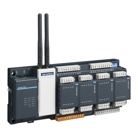
IDEC SX5A Series Use and care manual

SX5A AS-Interface
255
USA: 800-262-IDEC Canada: 888-317-IDEC
PLCs Operator Interfaces Automation Software Power Supplies Sensors Communication & Networking
Communication & Networking
SX5A AS-Interface (Communication Terminal and Repeater)
AS-Interface Communication Terminals (Slave Modules)
IP67 I/O Module
AS-Interface Ver. 2.1 compliant, capable of connecting 62 slaves
Compatible with 2- and 3-wire sensors
With AS-Interface power and input status indicators
Overload detection function on the sensor power supply
Output overload detection function (2 in/2 out model, 4 in/3 out model)
IP20 Terminal Block
AS-Interface Ver. 2.1 compliant, capable of connecting 62 slaves
Removable terminal blocks
Compatible with 2- and 3-wire sensors
AS-Interface power and input status indicators
IEC62026-2 compliant
Repeater
No address setting required.
The AS-Interface network can be extended up to 300 m.
IP65 protection
Easy connection to AS-Interface flat cables.
•
•
•
•
•
•
•
•
•
•
•
•
•
•
Part Numbers
SX5A AS-Interface Communication Terminals
Terminal I/O Specifications Part Numbers Applicable Base Module
(order separately)
Input Points Input Output Points Output
IP67 I/O
Module Connector
4 NPN — — SX5A-SWN40S02 SX5A-B3FF
4 PNP — — SX5A-SWN40K02N SX5A-B3FF
2 PNP 2 PNP SX5A-SWM22KS2N SX5A-B3FF
4 PNP 3 PNP SX5A-SWM43KS2N SX5A-B2FF
IP20 I/O
Module Terminal Block
4 NPN — — SX5A-SSN40S0N —
4 PNP — — SX5A-SSN40K0N —
4 PNP 3 PNP SX5A-SSM43KSN —
Base Modules
Applicable I/O Module Description Part Numbers
Base Module for IP67
I/O Module
4 in model
2 in/2 out model Substructure module to connect to AS-Interface
flat cables for AS-Interface bus and auxiliary power
SX5A-B3FF
4 in/3 out model SX5A-B2FF
Repeater
Description Part Number
A repeater can extend the AS-Interface Network up
to 300m. SX5A-RP1

SX5A AS-Interface
256 www.idec.com
PLCsOperator InterfacesAutomation SoftwarePower SuppliesSensors
Communication & Networking
Communication & Networking
Accessories
Description Part Numbers Notes
Hand-held Programming Device Assign slave addresses and monitor
system configuration SX9Z-ADR1N
Includes:
Programming device cable (SX9Z-CN1)
Programming device AC adapter (SX9Z-ADPT)
SwitchNet addressing port adapter (LA9Z-SNADP)
Operation manual (English/Japanese)
Programming Device Cable Connect the programming device to slave SX9Z-CN1
Programming Device
AC Adapter Charge the programming device SX9Z-ADPT AC input voltage: 100 to 240V AC
SwitchNet Addressing
Port Adapter
Connect the programing device cable
to SwitchNet contacts LA9Z-SNADP
AS-Interface Flat Cable
Branch Connector
Branch AS-Interface flat cable
to AS-Interface flat cable SX9Z-CF1
T-branch Connector Branch AS-Interface flat cable
to 2-wire cable LA9Z-SNTB
M12 Branch Connector Branch AS-Interface flat cable
to M12 cables SX9Z-CT1
AS-Interface Flat Cable
End Tube Protect the end of AS-Interface cable SX9Z-CPA1 Degree of protection: IP65
Protection Cap Ensure IP67 protection on
unused M12 I/O plugs SX9Z-CAP1

SX5A AS-Interface
257
USA: 800-262-IDEC Canada: 888-317-IDEC
PLCs Operator Interfaces Automation Software Power Supplies Sensors Communication & Networking
Communication & Networking
IP67 I/O Module
AS-Interface Ver. 2.1 compliant. A maximum of 62 slaves can be connected.
SX5A-SWN40S02 is a Ver. 2.0 standard slave, which allows for connection of up to 31 slaves.
Compatible with 2- and 3-wire sensors
With AS-Interface power and input status indicators
Overload detection function on the sensor power supply
Output overload detection function (2 in/2 out model, 4 in/3 out model)
IEC62026-2 compliant
•
•
•
•
•
•
•
Specifications
Models SX5A-SWN40S02 SX5A-SWN40K02N SX5A-SWM22KS2N SX5A-SWM43KS2N
General
Rated Operating
Voltage (Ue) 26.5 to 31.6V DC supplied from AS-Interface line
Rated Operating
Current (Ie)
≤ 40mA (without sensor)
240mA maximum
≤ 40mA (without sensor)
140mA maximum
≤ 40mA (without sensor)
240mA maximum
External Auxiliary
Power Supply U (AUX)—20 to 30V DC PELV (protective very-low voltage: protection
class 3 VDE0106 / IEC60364-4-41 compliant)
Operating Temperature –25 to +60°C (no freezing)
Storage Temperature –25 to +85°C (no freezing)
Degree of Protection IP67 (EN60529); Attach SX9Z-CAP1 protection caps on unused I/O connectors.
Connection Method Insulation displacement technology for flat cables (yellow/black)
M12 connector for I/O
Weight 100g 150g
Mounting Method Screw mounting on base module
Input
Input Points/Signals
4DC inputs
2- and 3-wire sensors
(NPN)
4DC inputs
2- and 3-wire sensors (PNP)
2DC inputs
2- and 3-wire sensors (PNP)
4DC inputs
2- and 3-wire sensors (PNP)
Input Power 20 to 31V DC supplied from AS-Interface line
Load Current Capacity
≤ 200mA (Tb ≤ 40°C)
≤ 150mA (Tb ≤ 60°C)
≤ 100mA (Tb ≤ 40°C)
≤ 75mA (Tb ≤ 60°C)
≤ 200mA (Tb ≤ 40°C)
≤ 150mA (Tb ≤ 60°C)
Provided with overload and short-circuit protection
OFF Current OFF ≤ 1mA OFF ≤ 2mA
ON Current (sink) ON ≥ 4.5mA ON ≥ 4mA
Protection Circuit Input current limit ≤ 8mA
Output
Output Points/Signals —
2 PNP transistor outputs
(with overload/short-circuit
protection)
3 PNP transistor outputs
(with overload/short-circuit
protection)
Output Power — Supplied from external auxiliary power supply U (AUX)
Voltage — External auxiliary power voltage U (AUX) – 0.5V
Current — 1A per output point 2A (OUT1, OUT2) 1.5A
(OUT3) 4A total
Communication Error — Output turns off
Communication
Slave Type Standard slave A/B slave
Profile
IO 0 0 B 7
ID 1 A A A
ID2 — 2 2 2
Data Bits
D0
D1
D2
D3
Input
IN1
IN2
IN3
IN4
Output
—
—
—
—
Input
IN1
IN2
IN3
IN4
Output
—
—
—
—
Input
—
—
IN3
IN4
Output
OUT1
OUT2
—
—
Input
IN1
IN2
IN3
IN4
Output
OUT1
OUT2
OUT3
—

SX5A AS-Interface
258 www.idec.com
PLCsOperator InterfacesAutomation SoftwarePower SuppliesSensors
Communication & Networking
Communication & Networking
Specifications
Models SX5A-SWN40S02 SX5A-SWN40K02N SX5A-SWM22KS2N SX5A-SWM43KS2N
LED Indicators
PWR AS-Interface power: Green LED
AUX — External auxiliary power U (AUX): Green LED
IN 4 yellow LEDs 2 yellow LEDs 4 yellow LEDs
OUT — 2 yellow LEDs 3 yellow LEDs
FAULT
Error indication: Red LED
ON: Communication error or address 0
Flash: Sensor power supply or output is overloaded
Address
Assignment Addressing Method
Remove the protection cap from the addressing port on the I/O module. Connect the hand-held programming device (SX9Z-
ADR1N) to the addressing port on the I/O module using the programming device cable (SX9Z-CN1), then the I/O module
stops communication through the AS-Interface line. Change slave addresses using the programming device.
Certification AS-International Association
Standards UL/c-UL, CE

SX5A AS-Interface
259
USA: 800-262-IDEC Canada: 888-317-IDEC
PLCs Operator Interfaces Automation Software Power Supplies Sensors Communication & Networking
Communication & Networking
IP20 I/O Module
AS-Interface Ver. 2.1 compliant
A maximum of 62 slaves can be connected.
Removable terminal blocks
Communication monitor function
Compatible with 2- and 3-wire sensors
AS-Interface power and input status indicators
IEC62026-2 compliant
•
•
•
•
•
•
•
Specifications
Models SX5A-SSN40S0N SX5A-SSN40K0N SX5A-SSM43KSN
General
Rated Operating Voltage (Ue) 26.5 to 31.6V DC supplied from AS-Interface line
Rated Operating Current (Ie) ≤ 30mA (without sensor) ≤ 35mA (without sensor)
External Auxiliary
Power Supply U (AUX)—20 to 30V DC PELV (protective very-low voltage: protec-
tion class 3 VDE0106 / IEC60364-4-41 compliant)
Operating Temperature –25 to +60°C (no freezing)
Storage Temperature –25 to +85°C (no freezing)
Degree of Protection IP20 (EN60529)
Connection Method Removable terminal block: Applicable wire size ≤ 2.5mm2 (14 AWG)
Weight 150g
Mounting Method DIN rail mounting
Input
Input Points/Signals 4 DC inputs, 2- and 3-wire sensors
(NPN) 4 DC inputs, 2- and 3-wire sensors (PNP)
Input Power Supplied from AS-Interface line (default: internal switch set to INT)
Supplied from an external 12 to 24V DC PELV (internal switch set to EXT)
Load Current Capacity ≤ 150mA (provided with overload and short-circuit protection)
OFF Current OFF ≤ 2mA
ON Current (sink) ON ≥ 4mA
Output
Output Points/Signals —3 PNP transistor outputs
(with overload/short-circuit protection)
Output Power —Supplied from external auxiliary
power supply U (AUX)
Voltage —External auxiliary power
voltage U (AUX) – 0.5V
Current —
3A max. (OUT1), 1.5A max. (OUT2, OUT3),
6A total (Tb ≤ 40°C)
2A max. (OUT1), 1A max. (OUT2, OUT3),
4A total (Tb ≤ 60°C)
Communication Error — Output turns off
Communication
Slave Type A/B slaves
Profile
IO 0 7
ID A A
ID2 0 0
Data Bits
D0
D1
D2
D3
Input
IN1
IN2
IN3
IN4
Output
—
—
—
—
Input
IN1
IN2
IN3
IN4
Output
OUT1
OUT2
OUT3
—

SX5A AS-Interface
260 www.idec.com
PLCsOperator InterfacesAutomation SoftwarePower SuppliesSensors
Communication & Networking
Communication & Networking
Specifications
Models SX5A-SSN40S0N SX5A-SSN40K0N SX5A-SSM43KSN
LED Indicators
PWR AS-Interface power: Green LED
AUX — External auxiliary power U (AUX): Green LED
IN 4 yellow LEDs
OUT — 3 yellow LEDs
FAULT
Error indication: Red LED
ON: Communication error or address 0
Flash: Sensor power supply or output is overloaded
INT Input power supplied from AS-Interface line: Green LED
Address
Assignment Addressing Method
Connect the hand-held programming device (SX9Z-ADR1N) to the addressing port on the I/O module using the program-
ming device cable (SX9Z-CN1), then the I/O module stops communication through the AS-Interface line. Change slave
addresses using the programming device.
Certification AS-International Association
Standards UL/c-UL, CE

SX5A AS-Interface
261
USA: 800-262-IDEC Canada: 888-317-IDEC
PLCs Operator Interfaces Automation Software Power Supplies Sensors Communication & Networking
Communication & Networking
Internal Circuits
SX5A-SWN40S02 SX5A-SWN40K02N SX5A-SWM22KS2N
PWR
AS-i–
AS-i+
AUX+
AUX
AUX–
Sensor+
Sensor–
FAULT
M12 ×1 connector
1
4
3
2
5
1
4
3
2
5
IN+
IN4
IN–
IN4
NC
PE
PNP
output
sensor
IN+
IN3
IN–
IN3
IN4
PE
For 3-wire sensor
Connect to protective
g
round on control panel.
AUX+
AUX+
AUX–
AUX–
1
4
3
2
5
1
4
3
2
5
NC
OUT1
OUT–
OUT1
OUT2
PE
NC
OUT2
OUT–
OUT2
NC
PE
Load
SX5A-SWM43KS2N SX5A-SSN40S0N
IN+ IN+ IN+ IN+
IN2 NC IN4 NC
IN1 IN2 IN3 IN4
IN1 IN2 IN3 IN4
IN– IN– IN– IN–
PE PE PE PE
PWR
AS-i–
AS-i+
AUX+
AUX
AUX–
AUX+
AUX+
AUX–
AUX–
Sensor+
Sensor–
1
FAULT
2
4
3
5
1
4
3
2
5
1
4
3
2
5
1
4
3
2
5
AUX+
AUX– PE
NC
OUT2
OUT–
OUT2
NC
PE
NC
OUT3
OUT–
OUT3
NC
PE
NC
OUT1
OUT–
OUT1
OUT2
M12 × 1 connector
For 3-wire sensor
Connect to protective
g
round on control panel.
4 inputs
Load
PNP
output
sensor
AS-i–
EXT
IN
I+
INT EXT
UEXT
Input Port Power
Selector Switch Position
4 inputs IN1...IN4
I–
IN
INT
AS-i+
PWR
FAULT
–+
For 3-wire sensor
NPN
output
sensor
For 3-wire sensor
NPN
output
sensor
SX5A-SSN40K0N SX5A-SSM43KSN
PNP
output
sensor
AS-i– EXT
IN I+
UEXT
I–
IN
INT
AS-i+
PWR
FAULT
PNP
output
sensor
For 3-wire sensor For 3-wire sensor
4 inputs IN1...IN4
INT EXT
Input Port Power
Selector Switch Position
AUX+
AUX
AUX–
PNP
output
sensor
AS-i–
EXT
IN I+
UEXT
4 inputs IN1...IN4
I–
IN
INT
AS-i+
PWR
FAULT
PNP
output
sensor
For 3-wire sensor For 3-wire sensor
Load
3 outputs O1...O3
INT EXT
Input Port Power
Selector Switch Position

SX5A AS-Interface
262 www.idec.com
PLCsOperator InterfacesAutomation SoftwarePower SuppliesSensors
Communication & Networking
Communication & Networking
Connector Arrangement
SX5A-SWN40S02
SX5A-SWN40K02N SX5A-SWM22KS2N SX5A-SWM43KS2N
ADDR
1
1
1
1
2
2
22
3
3
3
34
44
4
IN3 IN4
OUT1 OUT2
PWR
FAULT
ADDR
1
1
1
1
22
2
2
3
3
3
3
4
4
4
4
IN1 IN2
IN3 IN4
PWR
FAULT
AUX
ADDR
1
1
2
2
3
34
1
1
2
2
3
3
4
4
1
1
1
2
2
2
3
3
3
4
4
4
4
IN2
IN1
IN4
IN3
OUT1 OUT2
OUT3
PWR
FAULT
AUX
5
5
55
55 55
5
55
5
5
5
5
Terminal Arrangement
SX5A-SSN40S0N, SX5A-SSN40K0N SX5A-SSM43KSN
I-1 I-2 I-3 I-4
IN1 IN2 IN3 IN4
I+1 I+2 I+3 I+4
1 2 3 4
1 2 3
IN
FAULT INT
PWR
ADDR
SX5A–SSM43KSN
AS-i+ AS-i–
AUX
OUT
AUX+ AUX–
01 0-1 02 0-2
03 0-3
Label (for user)
Auxiliary Voltage
Terminal Assignment
Input Terminal
Assignment
AS-Interface Terminal
Assignment
I-1 I-2 I-3 I-4
IN1 IN2 IN3 IN4
I+1 I+2 I+3 I+4
1 2 3 4
IN
FAULT INT
PWR
ADDR
SX5A–SSN40K0N
AS-i+ AS-i–
Output Terminal
Assignment
Label (for user)
Input Terminal
Assignment
AS-Interface Terminal
Assignment
Input Port Power Selection
Power for input ports and connected sensors can be supplied from either inside
(AS-Interface) or outside (external power supply). The selection is done using a
switch inside the I/O module.
While the input power is supplied from inside, the INT LED remains on. While the
input power is supplied from outside, the INT LED remains off. I/O statuses are
indicated on the front LED indicators
1. Unlock
Press on BOTH sides.
2. Open
Pull upper part until STOP.
EXT
INT
3. Set switch
INT: sensor supply from AS-Interface
EXT: external sensor supply
Switchin
g
the input power supply INT/EXT

SX5A AS-Interface
263
USA: 800-262-IDEC Canada: 888-317-IDEC
PLCs Operator Interfaces Automation Software Power Supplies Sensors Communication & Networking
Communication & Networking
Dimensions
SX5A-SWN40S02
SX5A-SWN40K02N
SX5A-SWM22KS2N Base module is separately ordered SX5A-SWM43KS2N Base module is separately ordered
118
73.5 34.5
60
36 18.7
4
150
34.573.5
4
18.7
60
36
SX5A-B3FF SX5A-B2FF
112
118
77.5
4
48
12 PE
112
150
77.5
4
48
12 PE
SX5A-SSN40S0N
SX5A-SSN40K0N
SX5A-SSM43KSN
22.5
105
102.3
102
All dimensions in mm.

SX5A AS-Interface
264 www.idec.com
PLCsOperator InterfacesAutomation SoftwarePower SuppliesSensors
Communication & Networking
Communication & Networking
Repeater
SX5A-RP1
No address setting required
An AS-Interface network can be extended up to 300 m.
IP65 protection
Insulation displacement technology allows easy connection to AS-Interface flat
cables.
Input status of AS-Interface 1 and 2 are displayed with LED indicators.
The SX5A-RP1 repeater is used to extend the AS-Interface cable. One repeater
extends the length of network up to 100 m. A maximum of two repeaters can be
used in a network, enabling the construction of a network of up to 300 m.
•
•
•
•
•
•
Specifications
Models SX5A-RP1
General
Input Voltage 26.5 to 31.6V DC
Current 60mA (per segment), 120mA (total)
Operating Temperature 0 to +55°C (no freezing)
Storage Temperature –25 to +75°C (no freezing)
Operating Humidity 30 to 95% RH (no condensation)
Degree of Protection IP65
Insulation Resistance 5 MΩ minimum (500V DC megger)
Dielectric Strength 1000V AC, 1 minute
Applicable Wire AS-Interface flat cable
Weight Approx. 170g
Dimensions 60W x 118.5H x 22.5D mm
Mounting Screw mounting
Standard CE
LED Indicators (see Dimensions)
Indicators Color (when ON) Description
AS-Interface 1 Green Power is supplied to line 1.
AS-Interface 2 Green Power is supplied to line 2.
Dimensions Mounting Hole Layout System Setup
22
60
AS-Interface
Cable 1
AS-Interface
Cable 2
118.5
12
All dimensions in mm.
4.5
107
39
100 m max.
AS-Interface
Master
AS-Interface
Power Supply
AS-Interface
Power Supply
AS-Interface
Power Supply
Remote I/O
Repeater Repeater
Remote I/O Remote I/O
100 m max.
300 m max.
100 m max.
Segment Segment

SX5A AS-Interface
265
USA: 800-262-IDEC Canada: 888-317-IDEC
PLCs Operator Interfaces Automation Software Power Supplies Sensors Communication & Networking
Communication & Networking
Address Assignment for Communication Terminals
Remove the protection cap from the addressing port on the I/O module.
Connect the hand-held programming device (SX9Z-ADR1N) to the addressing
port on the I/O module using the programming device cable (SX9Z-CN1), then the
I/O module stops communication through the AS-Interface line. Change slave
addresses using the programming device.
For addressing procedures, see the user’s manual for the hand-held programming
device.
Hand-held programming
device SX9Z-ADR1N
Programming device cable
SX9Z-CN1
Addressing port
Addressing port
SX5A I/O Terminal (IP20)
• SX5A-SSN40S0N
• SX5A-SSN40K0N
• SX5A-SSM43KSN
SX5A I/O Terminal (IP67)
• SX5A-SWN40S02
• SX5A-SWN40K02N
• SX5A-SWM22KS2N
• SX5A-SWM43KS2N
Using SwitchNet Addressing Port Adapter on HW
To open the addressing port lid, insert a screwdriver into the side slot as shown.
Do not lose the lid.
Addressing
port lid
SwitchNet addressing
port adapter LA9Z-SNADP
Hand-held programming device
Attach the addressing port adapter to the programming device cable and insert
the addressing port adapter into the addressing port on the communication block.
Address Assignment for SwitchNet
Turn off the power to the SwitchNet control unit and open the lid of the address-
ing port. Connect the programming device cable (SX9Z-CN1) to the hand-held
programming device (SX9Z-ADR1N) and attach the SwitchNet addressing port
adapter (LA9Z-SNADP) to the programming device cable (SX9Z-CN1). Insert the
addressing port adapter into the addressing port on the SwitchNet control unit.
Change slave address using the programming device.
For addressing procedures, see the user’s manual for the hand-held programming
device. After completing address assignment, reattach the lid to the addressing
port.
SwitchNet L6
communication block
Programming device
cable SX9Z-CN1
Hand-held programming
device SX9Z-ADR1N
SwitchNet addressing
port adapter LA9Z-SNADP
SwitchNet HW
communication block
Using SwitchNet Addressing Port Adapter on L6
To open the addressing port lid, insert a screwdriver into the right-side hole as
shown. The addressing port lid can be removed from the communication block by
pulling it out.
SwitchNet addressing
port adapter LA9Z-SNADP
Addressing
port lid
Attach the addressing port adapter to the programming device cable and insert
the addressing port adapter into the addressing port on the communication block.

SX5A AS-Interface
266 www.idec.com
PLCsOperator InterfacesAutomation SoftwarePower SuppliesSensors
Communication & Networking
Communication & Networking
Hand-held Programming Device
Model SX9Z-ADR1N
Standards CE
Power Supply Powered by built-in battery (recharged using AC adapter)
Operation Time 8 hours or 250 read/write operations after full charge
Charging Time Approx. 14 hours
Operating Temperature 0 to +55°C
Storage Temperature –25 to +85°C (no freezing)
Degree of Protection IP20
Weight Approx. 275g
Communication Specifications AS-Interface Version 2.1
Operation Slave address assignment and data read/write (compatible with the 62-slave mode)
Connection Connects to a slave using programming device cable
This manual suits for next models
8
Table of contents
