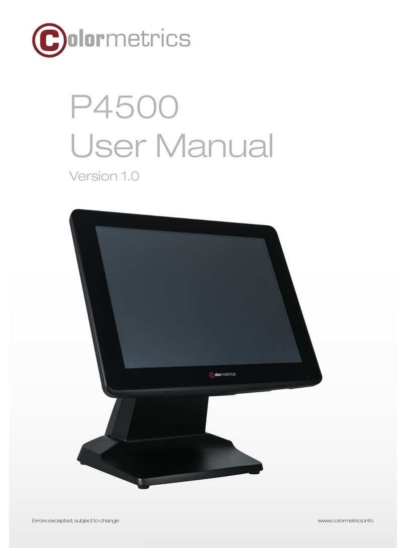
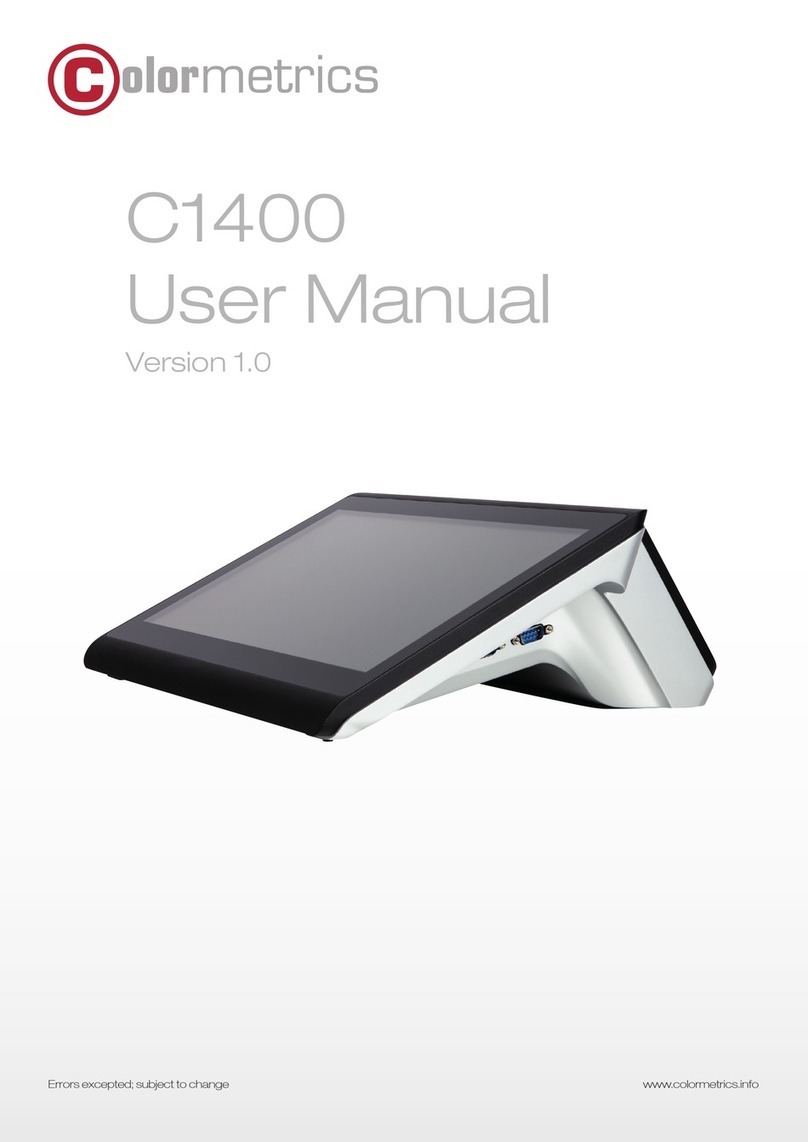
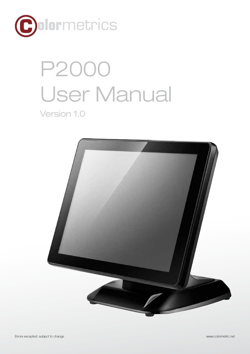
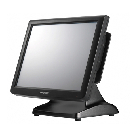
Colormetrics P4500 User manual

Errors excepted; subject to change www.colormetrics.info
P4500
User Manual
Version 1.0

23
www.colormetrics.infowww.colormetrics.infoColormetrics P4500 Colormetrics P4500
Copyright 2017 Colormetrics. All Rights Reserved.
This manual, and the software and firmware described in it are copyrighted by their respective owners
and protected under the laws of the Universal Copyright Convention. You may not reproduce, transmit,
transcribe, store in a retrieval system, or translate into any language, in any form or by any means,
electronic, mechanical, magnetic, optical, chemical, biological, molecular, manual, or otherwise, any
part of this publication without the express written permission of the publisher.
All products and trade names described within are mentioned for identification purposes only. No affili-
ation with or endorsement of the manufacturer is made or implied. Product names and brands appearing
in this manual are registered trademarks of their respective companies.
The information published herein has been checked for accuracy as of publishing time. No represen-
tation or warranties regarding the correctness of this document for any use are made or implied by the
publisher. We reserve the right to revise this document or make changes in the specifications of the
product described therein at any time without notice and without obligation to notify any person of such
revision or change.
COPYRIGHT SAFETY INSTRUCTIONS
1. Read these instructions carefully. Keep these instructions for future reference.
2. Please disconnect the equipment from AC outlet before cleaning.
Don’t use liquid or spray detergents for cleaning. Use a moist sheet or cloth for cleaning.
3. Please keep the equipment in a room with low humidity.
4. Lay the equipment on a reliable surface when installing. A drop or fall could cause injury.
5. Make sure power cord lies in such a way that people cannot step on it.
Do not place anything over the power cord.
6. All cautions and warnings on the equipment should be noted and adhered to.
7. If the equipment is not used for long time, disconnect it from the mains to avoid being damaged
by transient over voltage.
8. Never pour any liquid into the opening; this could cause a fire or electrical shock.
9. If one of the following situations arises, get the equipment checked by service personnel:
a. The power cord or plug is damaged.
b. Liquid has penetrated into the equipment.
c. The equipment has been exposed to moisture.
d. The equipment does not work well or you cannot get it work according to the user manual.
e. The equipment has been dropped and is damaged.
10. Do not leave the equipment in an unconditional environment, at a storage temperature below
-20°C or above 60°C, as it may damage the equipment.
11. Unplug the power cord when doing any service or adding optional kits.
Lithium Battery Caution:
Danger of explosion arises if the battery is incorrectly replaced. Replace only the original
or equivalent type recommended by the manufacturer. Dispose of used batteries according to the
manufacturer’s instructions.
CE Notice
This device complies with the requirements of the CE directive.
WEEE Notice
This appliance is labeled in accordance with European Directive 2002/96/EC concerning waste electrical
and electronic equipment (WEEE). The Directive determines the framework for the return and recycling of
used appliances as applicable throughout the European Union. This label is applied to various products to
indicate that the product is not to be thrown away, but rather reclaimed upon end of life per this Directive.
45
www.colormetrics.infowww.colormetrics.infoColormetrics P4500 Colormetrics P4500
COPYRIGHT 2
SAFETY INSTRUCTIONS 3
CE NOTICE 3
1 PACKING LIST 5
1-1. Standard Accessories 5
1-2. Optional Accessories 5
2 SYSTEM VIEW 6
2-1. Rear View (I/O Type A) 6
2-2. Back View 7
2-3. Specification 8
2-4. Internal Layout 9
3 PIN DEFINITION 10
4 REAR I/O INTERFACE 12
5 SYSTEM ASSEMBLY & DISASSEMBLY 14
5-1. HDD 14
5-2. Memory 15
5-3. M.2 SSD 17
5-4. MSR/iButton/RFID 18
5-5. VFD / 8"/10.4"/15" 2nd Display 19
5-6. 1D/2D Barcode scanner 22
6 DEVICE DRIVER INSTALLATION 23
6-1. Resistive Type Touch Panel and P-CAP 23
6-2. MagStripe Card Reader Configuration Utility 29
6-3. RFID 40
6-4. USB 2nd Display 45
6-5. Configuration Utility of i-Button Reader 48
6-6. VFD 53
7BIOS/UTILITY SETUP 58
7-1. Advanced 60
7-2. Security 65
7-3. Power 66
7-4. Boot 67
7-5. Exit 68
8. LCD SURFACE CLEANING 69
TABLE OF CONTENTS
7
1-1 Standard Accessories
a.
b.
a. System (with stand)
b. Power Adapter
c. Power Cord
d. Driver Bank
e. Cable D-SUB9 to RJ45
c.
d.
e
1-2 Optional Accessories
a.
b.
a. Single MSR
b. VFD
c. 8”/10.4”/15” 2nd Display
d. 1D or 2D Barcode
e. MSR + iButton
f. MSR+RFID
g. UPS Battery
c.
d.
Packing List
1
PACKING LIST

6www.colormetrics.infowww.colormetrics.infoColormetrics P4500 7
Colormetrics P4500
8
e.
f.
g.
2-1. Rear View
I/O Extension
Type A I/O Card Type B I/O Card
Type C I/O Card Type E I/O Card
System View
2
I/O Extension
8
e.
f.
g.
2-1. Rear View
I/O Extension
Type A I/O Card Type B I/O Card
Type C I/O Card Type E I/O Card
System View
2
I/O Extension
8
e.
f.
g.
2-1. Rear View
I/O Extension
Type A I/O Card Type B I/O Card
Type C I/O Card Type E I/O Card
System View
2
I/O Extension
Please make sure the 19V DC is plugged in the right direction before plugging in DC jack.
COM
Mic-in COM
SYSTEM VIEW
9
2-2. Back View
☆☆Please make sure 19V DC plug in the right direction before plugging in DC jack.
VFD Cover/8”/10.4” 2
nd
Display (Optional)
MSR/iButton/RFID
(Optional)
HDD Cover
9
2-2. Back View
☆☆Please make sure 19V DC plug in the right direction before plugging in DC jack.
VFD Cover/8”/10.4” 2nd Display (Optional)
MSR/iButton/RFID
(Optional)
HDD Cover
15" Display, VFD pole (optional)

89
www.colormetrics.infowww.colormetrics.infoColormetrics P4500 Colormetrics P4500
10
2-3. Specification
Model Ares755J
Display Display Size 15" TFT LCD
Resolution 1024 X 768
Brightness /Color 350 cd/㎡, 16.7M colors
Backlight LED
Touch Panel Type 5 wire resistive or projected capacitive touch
Processor CPU/ Chipset Intel® Celeron 3965U (Dual Core 2MB Cache, up to
2.20GHz)
Memory X 1 (DDR4-2133MHz SO-DIMM, up to 16GB)
Storage X 1 (2.5” SATAIII HDD or SSD ) / X 1 M.2 (Support 2242
& 2280) (SSD)
I/O Connectors USB 3.0 X 4
Powered COM X 3 (RJ45 x 1 with DC 5V/12V selectable)
Cash Drawer Port X 1 (12V/24V RJ11 cash drawer port)
VGA X 1
LAN X 1 (RJ45, 10/100/1000 Base-T)
I/O Expansion Type A X 1 UPS, X 2 USB2.0, X 1 Line-out
Type B X 1 UPS, X 1 COM (RJ45 with DC 5V/12V selectable), X
1 Line-out
Type C X 1 24V Powered USB, X 2 USB 2.0, X 1 Mic-in, X 1
Line-out
Type E X 4 USB2.0, X 1 COM (RJ45 with DC 5V/12V selectable)
Optional Peripherals VFD / 8"/10.4” 2nd display / MSR / iButton / RFID /
fingerprint reader / 1D/2D barcode scanner / WiFi
Power Supply 90W or 150W 19V lockable 3-pin DC input power adapter
OS Support Linux / Win 10 IoT Enterprise
Environment Temperature Operation 32° to 95° F (0° to 35° C)
Storage -4° to 140° F (-20° to 60° C)
Relative Humidity 20% to 80% non-condensing
Dimension (W x H x D) 374 X 356 X 207 mm
11
2-4. Internal Layout
M/B PCBA
Colormetrics P4500

10 11
www.colormetrics.infowww.colormetrics.infoColormetrics P4500 Colormetrics P4500
12
1. J1: eDP pin Definition
No. Definition No. Definition
1
NC
16
GND
2
GND
17
DDI2_DP_HPD
3
DDI2_DP_TX1_DN
18
GND
4
DDI2_DP_TX1_DP
19
GND
5
GND
20
GND
6
DDI2_DP_TX0_DN
21
GND
7
DDI2_DP_TX0_DP
22
BL_Enable
8
GND
23
BL PWM DIM
9
SOC_EDP1_AUX_P
24
NC
10
SOC_EDP1_AUX_N
25
NC
11
U3Rxp1
26
+12V
12
+V3.3V
27
+12V
13
+V3.3V
28
+12V
14
NC
29
+12V
15
GND
30
NC
2. SATA1: 7+15 PIN SATA Pin Definition
No. Definition No. Definition
1
GND
12
GND
2
SATA_TX0_P
13
GND
3
SATA_TX0_N
14
+V5
4
GND
15
+V5
5
SATA_RX0_N
16
+V5
6
SATA_RX0_P
17
GND
7
GND
18
GND
8
N/C
19
GND
9
N/C
20
N/C
10
N/C
21
N/C
11
GND
22
N/C
3. SPK1: Int. Speaker Pin Definition
No. Definition
1
Left Out +
2
Left Out -
3
Right Out-
4
Right Out+
Pin Definition
3
13
4. SW1: Power Button Pin Definition
No. Definition
1
+5V standby
2
+5V
3
Power-ON#
4
GND
5. JBAT1: Power Button Pin Definition
No. Definition
3
Clear CMOS#
5
GND
6. CN1: Touch panel Pin Definition
No. Definition
1
+5V
2
USB D-
3
USB D+
4
GND
7. CN4: Sideway MSR connector Pin Definition
No. Definition
1
+5V
2
+5V
3
GND
4
USB D-
5
USB D+
6
USB D-
7
USB D+
8
USB D-
9
USB D+
10
GND
11
+3.3V
12
+3.3V
13
N/C
8. CN2: VFD connector Pin Definition
No. Definition
1
RTS#
2
DSR#
3
TxD
4
RxD
5
CTS#
6
DTR#
7
+5V
8
USB D-
9
USB D+
10
GND
PIN DEFINITION REAR I/O INTERFACE

12 13
www.colormetrics.infowww.colormetrics.infoColormetrics P4500 Colormetrics P4500
14
1. JS1: DC Jack Pin Definition
No. Definition
1 +19V
2 Ground
3 +19V
2. VGA1: VGA connector Pin Definition
No. Definition
1
RED
2
GREEN
3
BLUE
4
N/C
5
GND
6
GND
7
GND
8
GND
9
N/C
10
GND
11
N/C
12
SPD
13
HSYNC
14
VSYNC
15
SPCLK
3. CN6, CN7: 2-Layer USB3.0 pin Definition
No. Definition No.
Definition
1
+5V
8
TX-
2
D-
9
TX+
3
D+
10
+5V
4
GND
11
D-
5
RX-
12
D+
6
RX+
13
GND
7
GND
4. COM1, COM2, COM3: RJ45 Pin Definition
No. Definition
1
5V/12V/Ring#
2
DSR#
3
GND
4
DTR#
5
RTS#
6
CTS#
7
TxD
8
RxD
Rear I/O Interface
4
15
5. LAN1: RJ45 Pin Definition
No. Definition
1
MDI0A+
2
MDI0A-
3
MDI1A+
4
MDI1A-
7
MDI2A+
8
MDI2A-
9
MDI3A+
10
MDI3A-
6. CN8: RJ11 (Cash Drawer) connector Pin Definition
No. Definition
1
GND
2
C/D_OPEN#
3
C/D Status
4
+12V/+24V
5
N/C
6
GND
REAR I/O INTERFACE

14 15
www.colormetrics.infowww.colormetrics.infoColormetrics P4500 Colormetrics P4500
16
5-1. HDD
1. Remove the 2 hard drive cover screws then remove the hard drive cover.
2. Remove the 2 screws from the hard drive bracket
3. Slide the hard-drive bracket in an outward direction to remove it from the system
4. Remove the 4 hard drive bracket screws
5. Remove the hard drive from the hard drive bracket
System Assembly & Disassembly
5
3
5
17
5-2. Memory
1. Remove the 2 hard drive cover screws then remove the hard drive cover
2. Remove the 2 hard drive bracket screws then remove the hard drive bracket
3. Slide the hard-drive bracket in an outward direction to remove it from the system
4. Remove the 2 I/O board screws
5. Remove the 1 VFD screw
4
5
3
SYSTEM ASSEMBLY & DISASSEMBLY

16 17
www.colormetrics.infowww.colormetrics.infoColormetrics P4500 Colormetrics P4500
18
6. Remove the 1 Barcode screw
7. Remove the 2 VGA screws
8. Remove the back cover
9. Install memory into the socket
10. Push down on memory
6
7
8
9
10
19
5-3. M.2 SSD
1. Remove the screw and standoff from location of M.2 2280
2. Install the standoff to the location of M.2 2242
3. Install the M.2 2242 SSD into the socket
4. Push down on memory then fasten the screw
1
2
3
4

18 19
www.colormetrics.infowww.colormetrics.infoColormetrics P4500 Colormetrics P4500
20
5-4. MSR / iButton / RFID
1. Remove MSR cover
2. Fasten the MSR holder with 2 screws
3. Plug the MSR cable into the MSR connector
4. Reinstall the MSR cover with 2 screws
1
2
3
4
21
5-5. VFD / 8”/10.4”/15” 2nd Display
5-5-1. VFD/ 8”/10.4” 2nd Display
1. Remove top cover
2. Either plug the VFD cable into the VFD connector or plug the 8”/10.4” 2nd display cable into the
2nd display’s connector (note: display connector can only be connected to one device at a time)
3. Install VFD with 2 screws / Install 8”/10.4” 2nd display with 2 screws
1
2
3

20 21
www.colormetrics.infowww.colormetrics.infoColormetrics P4500 Colormetrics P4500
22
5-5-2. 15” 2nd Display
1. Remove back cover of the stand
2. Plug in DC 19V, VGA and the end of RJ45 of “RJ45 to D-SUB 9P” cables to the DC Jack, VGA
and RJ45 ports on the system
3. Arrange the cables, as shown in the figure
4. Connect the end of D-SUB 9P female of the “D-SUB 9P to DC Jack” cable to the other end
of D-SUB 9P male cable
1
c
2
3
4
23
5. Fasten the 6 screws on the extended base to the frame base
6. Install the tube into the extended base and arrange the cables as shown in the figure then
restore the back cover of the stand
7. Plug in the other end of VGA and DC Jack of the “D-SUB 9P to DC Jack” cables to the 15” 2nd
display
8. Install complete
c
5
6
7
8
☆☆Refer to P.66 using the power menu to enable the 12V power to the COM port is connected
to the 15” 2nd display.
Refer to page 66 to use the power menu to enable the 12V power
and connect it to the 2nd 15‘‘ display.

22 23
www.colormetrics.infowww.colormetrics.infoColormetrics P4500 Colormetrics P4500
24
5-6. 1D/2D Barcode scanner
1. Remove barcode scanner cover
2. Plug the barcode scanner cable into the barcode connector
3. Install the barcode scanner with 2 screws
1
25
6-1. Resistive and P-CAP Type Touch Panel
1. Click “Next”.
2. Click “Next”.
Device Driver Installation
6
26
3. Click “Next”.
4. Select “None”, Click “Next”.
5 Click “OK”.
DEVICE DRIVER INSTALLATION

24 25
www.colormetrics.infowww.colormetrics.infoColormetrics P4500 Colormetrics P4500
27
6. Select “Support Multi-Monitor System”, Click “Next”.
7. Click “Next”.
28
8. Click “Next”.
9. Click “Next”.

26 27
www.colormetrics.infowww.colormetrics.infoColormetrics P4500 Colormetrics P4500
29
10. Select “Create a eGalaxTouch Utility shortcut on desktop”, Click “Next”.
30
11. Would you do 4 point calibration now? Click “Yes”. (Resistive Touch only)
12. Do 4 points aligrment to match display.
13. Calibration utility.

28 29
www.colormetrics.infowww.colormetrics.infoColormetrics P4500 Colormetrics P4500
31
6-2. MagSwipe Card Reader Configuration Utility
The MagSwipe Configuration Utility is used to set up the output format of MagSwipe
Installation
The steps below guide you how to install the Utility program
lInsert the setup CD
lRun the 80066804-006_MagSwipe_Configuration_Software_V2_1_A setup file that is
located in the Software folder of CD.
lFollow the wizard to complete the installation.
Launching Program
The steps below guide you how to load the Utility program.
lFrom Start/Programs, click MagSwipe folder
lClick MagSwipe Configuration Utility to launch the program.
32
Configuration
Select Reader Interface
The reader to be configured should be connected. Select the corresponding connected reader
interface and click the Continue button

30 31
www.colormetrics.infowww.colormetrics.infoColormetrics P4500 Colormetrics P4500
33
After the interface selection is made, click the Continue button. The utility attempts to
communicate with the connected reader. If successful, the Home Menu Page is displayed. The
Home Menu Page is shown below
34
Change Basic Reader Setting
After selecting the appropriate interface for the reader, select one of the Home Menu Page buttons
to proceed with the Magnetic Stripe Reader (MSR) configuration process. The "Basic Reader
Settings" group defines the basic operating parameters and data output format of the reader.
Button Definitions
Send To MSR
When all the setting parameters are selected, use the "Send To MSR..." button to send
configuration data to the reader device. When the reader has received the data correctly, the
settings take effect immediately.
Load From File
The configuration data can be loaded into the configuration utility from a file that has been
previously saved. Select this command, start a "File Open" dialog, which allows selection of the
file.

32 33
www.colormetrics.infowww.colormetrics.infoColormetrics P4500 Colormetrics P4500
35
Save To File
The configuration data can be saved as a file and being used later to configure other readers.
When saving a configuration the "File Save" dialog is opened as shown below. Input a filename
and file location.
Default All
This button sets the reader with the default configuration parameters (the default factory settings).
The settings take effect immediately. The default parameters affect all reader configurations
settings.
Close
Close this dialog and return to the Home Menu Page.
36
General Settings
This group of configuration settings defines the basic operating parameters of the reader.
MSR Reading
This option will turn on or off the MSR. If MSR is disabled no data is sent out to host in any case.
The default is MSR Reading Enabled.
Decoding Method Settings
This option gives four kinds of decoding methods.
Raw Data (output in both forward and reverse directions)
Decoding in Both Directions (forward and reverse reading)
Decoding in Forward Direction only (card entering slot from LED end)
Decoding in Reverse Direction only (card entering slot from end opposite LED)
With the bi-directional operation, the user can swipe the card in both swipe directions and the data
encoded on the magnetic stripe will be output. In the single swipe direction selections, the card can
only be swiped in one specified direction to read the card. The default setting will decoding card
data with the card swiped in either the forward or the reverse direction.

34 35
www.colormetrics.infowww.colormetrics.infoColormetrics P4500 Colormetrics P4500
37
"Raw Data" is an output of the decoded magnetic stripe data in hexadecimal format (no ASCII
character conversion is performed). In the Raw Data setting, the reader outputs all track-decoded
data. The MSR will represent the raw data with two ASCII characters: the first ASCII character is
for high bits of the raw data byte and the second is for the low bits. For example, the two ASCII
characters "4"and "1"represent raw data byte 41h(01000001).
Beep Volume
The Beep volume can be adjusted to four loudness levels or off. Four loudness levels are:
Quick High
Quick Low
High
Low
The default is High beep.
Terminal Type
NoteBook
IBM-PC/AT
IBM-PC/AT, External keyboard
IBM-PC/AT, No External keyboard
The firmware can be programmed to interface as a keyboard wedge to 4 different types of
terminals. The default is IBM-PC/AT.
Inter-Character Delay :
2ms, 5ms, 10ms, 20ms, 50ms, 100ms;
This is the time period the reader will delay between sending successive characters. Some
terminals or computers (host) require an inter-character delay to simulate the effects of keystroke
delays. Choosing a longer inter-character delay causes the characters to be sent at a slower rate.
If the host system is not capable of receiving characters as fast as the reader can transmit, setting
38
an appropriate inter-character delay will keep the reader from overrunning the host input buffer.
The default is 2ms.
Default Page Button
After you click the Default Button, the general settings page will change back to the default value.
Settings are not sent to MSR until the "Send to MSR" button is clicked.
Help Button
Click the help button to open the help index for this section.
Pre/Postamble
Preamble
Characters can be added to the beginning of the reader's output string of data. These can be
special characters for identifying a specific reading station, to format a message header expected
by the receiving host, or any other character string. Up to nine ASCII characters can be defined for
the Premable.
Postamble
The Postamble serves the same purpose as the Preamble, except the extra characters are added
to the end of a data string. The Postamble can be added only after a terminator character, if
specified.
Track Prefix and Suffix
For some Host applications, it may be convenient to start or end a string of reader data with a
Sentinel or terminator character.The maximum Prefix/Suffix string is six charecters and its default
is NULL(no prefix or suffix).
Track Start Sentinels
Characters can be added to the beginning of each track data string to simulate the start of the track
data. These can be special characters for identifying a specific track.

36 37
www.colormetrics.infowww.colormetrics.infoColormetrics P4500 Colormetrics P4500
39
End Sentinel
The magnetic stripe End Sentinel character can be added to the end of a magnetic stripe data
string. This character simulates the end of character for track1, track2 or track3. This default is '?'
Track Settings
Track Selection
There are three tracks of information possible on a magnetic stripe. This option selects the tracks
that will be decoded (read). Note that the magnetic stripe reader must have the hardware
configuration (read head and circuits) for reading the specified tracks. If a single or dual track
reader is used, the heads must be positioned to read the tracks selected by this option. The default
is Any Track.(All tracks written on the card will be read).
Track Separator Selection
This option allows the user to select the character to be used to separate data decoded by a
multiple-track reader. The default value is CR
Send Start/End Sentinel
The reader can send the Start/End sentinel for a track, decoded without error.
40
Send LRC in Card Data
The reader can send the track LRC for a properly decoded track.
For Track 2 only Send Account Number
The reader can only send account Number if it is true. And if it is false, the reader sends all Track 2
data.
Send Error Indication
This option let reader to send out [SS]E[ES] if failed to read or missing data on a selected track.The
default is off.
The error output for track 1 is "%E?".
The error output for track 2 is ";E?".
The error output for track 3 is "+E?".
Keyboard Settings
Keyboard Settings
There are keyboard settings information on a magnetic stripe. MiniMag II will support following
foreign language keyboard and function key output for PS/2 and USB HID Keyboard Interface.

38 39
www.colormetrics.infowww.colormetrics.infoColormetrics P4500 Colormetrics P4500
41
Language Option
This option allows the user to select the keyboard language of US, Swiss, Swedish, Norwegian,
Italian, Spanish (Mexico), German, French, Japanese, UK and Universal. Universal language
sends out all the data as a series of ALT keypad sequence.
Function Key Output
The function key output be used to support the special key to delay card data output.
USB HID KB Polling Interview
The user can input the number between 1 to 255 for the delay of output.
Check Current Reader Setting
After you connect the device, the current reader configuration can be displayed by selecting this
button. The configuration data of the connected reader will be displayed like in the example:
42
6-3. RFID
6-3-1. Install driver
1. Check the Device Manager to verify the status of RFID reader.
Computer Management -> Device Manager -> Other devices (The device will show a question
mark if the installation is not done properly.)
2. Double-click to update driver.
41
Language Option
This option allows the user to select the keyboard language of US, Swiss, Swedish, Norwegian,
Italian, Spanish (Mexico), German, French, Japanese, UK and Universal. Universal language
sends out all the data as a series of ALT keypad sequence.
Function Key Output
The function key output be used to support the special key to delay card data output.
USB HID KB Polling Interview
The user can input the number between 1 to 255 for the delay of output.
Check Current Reader Setting
After you connect the device, the current reader configuration can be displayed by selecting this
button. The configuration data of the connected reader will be displayed like in the example:
Other manuals for P4500
1
Table of contents
Other Colormetrics Touch Terminal manuals

Colormetrics
Colormetrics V1200 User manual

Colormetrics
Colormetrics PS1000 User manual

Colormetrics
Colormetrics Vion User manual

Colormetrics
Colormetrics P4500 User manual

Colormetrics
Colormetrics V1506 User manual

Colormetrics
Colormetrics C1000 mPOS User manual

Colormetrics
Colormetrics P5100 User manual

Colormetrics
Colormetrics C1400 User manual

Colormetrics
Colormetrics P2500 User manual

Colormetrics
Colormetrics P2000 User manual