manuals.online logo
Brands
  1. Home
  2. •
  3. Brands
  4. •
  5. Festo
  6. •
  7. Touch Terminal
  8. •
  9. Festo CDSA-D3-RV Instruction Manual

Festo CDSA-D3-RV Instruction Manual

Translation of the original instructions
© 2020 all rights reserved to Festo SE & Co. KG
Pilz®, TORX® are registered trademarks of the respective trademark owners in cer
tain countries.
1 About this document
1.1 Purpose of the document
This document describes the handheld terminal CDSAD3RV.
This document is the safetyrelevant part of the operating instructions in accord
ance with the Machinery Directive 2006/42/EG.
Complete operating instructions are available for the product.
1.2 Applicable documents
All available documents for the product èwww.festo.com/sp.
Document Table of contents
Interface housing CAMIC Assembly instructions
Declaration of conformity Manufacturer's declaration of conformity with 2006/42
/ EC and other directives
Tab. 1 Applicable documents
1.3 Product labelling
• Observe the specifications on the product.
The product labelling enables identification of the product and shows the follow
ing information, forexample:
Product labelling (sample)
1 Type code
2 Part number
3 Production date (month/year)
4 Technical data (voltage/current)
5 Ambient temperature
6 Manufacturer
7 Manufacturer’s address
8 Country of origin
9 Plant number
10 UL inspection mark
11 KC identification
12 Serial number
13 CE conformity marking
Tab. 2 Product labelling (sample)
1.4 Specified standards
EN ISO 13850:2015
EN ISO 10218:2011
EN 602041:2006+A1:2009+AC:2010
EN 6094758:2007
EN 611312:2007
Tab. 3 Specified standards
1.4.1 Quantitative safety specifications for the emergency stop device and
the 3-position enabling switch
Festo provides a B10D value è 11.1 Handheld terminal CDSAD3RV.
Other values are not provided by Festo, e.g. SIL, PL and category. Reason: Festo
supplies the switching element, but does not evaluate the element. The customer
must connect and monitor the emergency stop device and the 3position enabling
switch for the application. The customer receives SIL or category with PL by the
method in which the emergency stop function and the enabling control function
are implemented in the machine.
1.4.2 Abbreviations
Abbrevi-
ation
English term Description
B10D – Number of cycles until dangerous failure of 10% of the
components (per channel)
MTTFDMean time to Failure Dan
gerous
Mean time to dangerous failure (per channel)
DC Diagnostic Coverage Diagnostic coverage
PL Performance Level Discrete level that specifies the ability of safetyrelated
devices to execute a safety function under foreseeable
conditions.
PFHDProbability of Failure per
Hour Dangerous
Average probability of a dangerous failure per hour
SIL Safety Integrity Level Safety integrity level
Tab. 4 Abbreviations
2 Safety
2.1 Safety instructions
– Only use the product in original status without unauthorised modifications.
Only the conversions and modifications described in this and the additional
documents are permitted.
– Only use the product if it is in perfect technical condition.
– Observe further applicable documents.
– Observe labelling on the product.
– Installation, commissioning, maintenance and disassembly should only be
conducted by qualified personnel.
– Observe the mounting and connection specifications.
– Take into consideration the ambient conditions at the location of use.
– Comply with specified critical limits.
– The cable must not be crushed by objects.
– Do not route the cable over sharp edges.
– Select the cable length to ensure sufficient access to the danger zone.
– When not in use, place and attach the product to the existing wall bracket.
– The product must be stored in such a way that control elements cannot be
actuated or damaged.
– Foreign matter or liquids must not penetrate the product.
– Check the product if damage is suspected.
2.2 Intended use
The intended use of the handheld terminal CDSAD3RV extends from monitoring
and parameterisation to the operation of machines, e.g.Festo handling systems.
The devices for the safety engineering are an emergency stop device and a 3posi
tion enabling switch.
The handheld terminal must not be used for temporary connection.
Remove nonfunctional or disconnected devices from the area of the user in order
to avoid accidental actuation of the nonfunctional emergency stop device.
All safety engineering equipment is designed with 2 circuits and permits imple
mentation of category 4 PL e in accordance with EN ISO 138491, taking into
account the actuation cycles with reference to the B10D values of the safety
devices.
2.3 Foreseeable misuse
The following areas of application are expressly excluded for the handheld termin
al CDSAD3RV:
– Use in potentially explosive areas or areas where there is a risk of fire
– Use in mining
– Outdoor use
2.4 Training of qualified personnel
This document contains information for people with the following prerequisites:
8135651
CDSA-D3-RV
Operator unit
8135651
202008
[8135653]
Brief instruction| Safety manual
Festo SE & Co. KG
Ruiter Straße 82
73734 Esslingen
Germany
+49 711 3470
www.festo.com
Target group Required knowledge and skills
Project planners Basic technical training (technical college, engineering training or corres
ponding work experience)
Knowledge of:
– the mode of operation of a PLC
– current valid safety regulations
– the application
Electrician Training in electrical engineering (in accordance with industrystandard
training guidelines)
Knowledge of:
– current valid safety regulations
– wiring guidelines
– circuit diagrams
– system analysis and troubleshooting
– professional electrical connections in accordance with national and
international regulations
Commissioner Basic technical training (technical college, engineering training or corres
ponding work experience)
Knowledge of:
– current valid safety regulations
– the mode of operation of the machine or system
– basic functions of the application
– system analysis and troubleshooting
– the setting options on the operating devices
Service technician Basic technical training (technical college, engineering training or corres
ponding work experience)
Knowledge of:
– the mode of operation of a PLC
– current valid safety regulations
– the mode of operation of the machine or system
– diagnostics options
– systematic error analysis and elimination
Tab. 5 Training of qualified personnel
3 Additional Information
– Accessories èwww.festo.com/catalogue.
4 Service
Contact your regional Festo contact person if you have technical questions
èwww.festo.com.
5 Product overview
5.1 Configuration
5.1.1 Product design
The handheld terminal CDSAD3RV is a portable operating and display device.
The colour display can be used to perform graphical tasks. The touchscreen
enables intuitive user guidance.
The devices for the safety engineering are an emergency stop device and a 3posi
tion enabling switch.
Front view
1Emergency stop device, 2circuit
2Touch sensitive keyboard
3Hand strap
4Menu key
Fig. 1 Front view
Rear view
1Device attachment
2Touch pen holder
33position enabling switch
4Connection shaft cover
5Strain relief and antikink device for
connecting cable (supplied with
connecting cable)
6USB port
7Rating plate
Fig. 2 Rear view
5.1.2 Connecting elements
5.1.2.1 Connection shaft
1Ethernet plug/communication
interface
2Pin header  main plug/supply and
control cables
Fig. 3 Connection shaft for handheld terminal CDSAD3RV
Connection
The following graphic shows the connection of the control cables (power supply,
emergency stop and enabling circuits) and the data cables to the interface hous
ing.
Fig. 4 Connection diagram: handheld terminal CDSAD3RV on interface housing
CAMIC
5.1.2.2 Emergency stop device
The handheld terminal CDSAD3RV has an emergency stop device. The emer
gency stop device is wired in 2 circuits and the contacts are designed as normally
closed contacts.
The redyellow emergency stop device on the handheld terminal CDSAD3RV
meets the requirements of EN ISO 13850.
Its mode of operation must be designed as a category 0 or category 1 stop based
on the risk assessment for the machine èEN 602041. The interconnection of
the forcedopening switch contacts must fulfil the category (in accordance with
EN ISO 138491) that is defined based on the risk analysis (in accordance with
EN ISO 12100:2010) of the machine.
WARNING!
Impairment of the function of emergency stop devices.
Impairment of the function of emergency stop devices can result in serious injur
ies or death of persons involved.
• Redyellow marked emergency stop devices must be effective at all times and
in all operating modes of a machine or system.
• Handheld terminals that are not connected to the machine and have a redyel
low emergency stop device, must be kept out of sight so they cannot be con
fused with functioning devices in an emergency.
• When unlocking the emergency stop device, do not cause an uncontrolled
restart.
• Do not use the emergency stop device as a substitute for other safety
devices.
• Do not use the emergency stop device on the handheld terminal as a replace
ment for the emergency stop switches to be attached directly to the machine.
• After violent impact with the handheld terminal (e.g.if it is dropped), check
the function of the emergency stop device.
• Check the correct mode of operation of the emergency stop device every 6
months by actuating it.
• For additional information on the emergency stop device and the emergency
stop function, observe the corresponding directives and standards.
5.1.2.3 3-position enabling switch
The handheld terminal CDSAD3RV has a 3position enabling switch. An essential
feature is the 2circuit design and the forced opening in accordance with
EN 609471 and EN 6094758 to the third switch position.
WARNING!
Danger to persons not recognised in time if the 3-position enabling switch is
used as a safety function.
The 3position enabling switch is only suitable for use in a safety function if the
person actuating the 3position enabling switch detects a hazard to people in
good time and can immediately take measures to avoid hazards. A hazard to per
sons that is not recognised in good time can result in injuries or death to the per
sons involved.
• As an additional measure, reduce the speed of the movement. Determine the
permissible speed based on a risk assessment.
• Do not initiate commands for hazardous statuses with a 3position enabling
switch alone. A second, deliberate start command is required for this, suchas
a key on the handheld terminal.
• Only the person who actuates the 3position enabling switch may be in the
danger zone.
• Check the correct mode of operation of the safety function every 6 months by
actuating all positions of the 3position enabling switch.
• For additional information on the 3position enabling switch, observe the cor
responding directives and standards.
Mode of operation
The 3position enabling switch can be in one of three different switch positions:
Switch setting Function 3-position
enabling switch
Switch contact
1 Neutral position not actuated Off (opened)
2 Enabling is actuated On (closed)
3 Panic is pressed Off (opened)
Tab. 6 Mode of operation of the 3position enabling switch
Normal actuation
Fig. 5 Switching path diagram for normal actuation
Panic actuation
When the actuating elements are pressed to the panic position, the switching ele
ment is mechanically designed so that the enabling position is skipped when it is
released:
Fig. 6 Switching path diagram for panic actuation
Category 4 PL e in accordance with EN ISO 138491 for the relevant safety func
tion can be reached with the use of the 3position enabling switch on two electric
al circuits and a suitable dynamic monitoring with the actuation cycles with refer
ence to the B10D value of the safety devices.
In accordance with EN 602041, the 3position enabling switch must be imple
mented in such a way that in position 1 (switch off function  the control element
is not actuated) and position 3 (Off function  the control element is pressed down
to the "panic position") at least one of the stop categories 0, 1 or 2 is initiated.
For the calculation of the PL of the enable safety function, the safety engineering
characteristic values (PL, PFHD and B10D values) of the involved components must
be included. Details on calculating the PL for the entire safety function
èEN ISO 138491(chapter6.3, appendixH and appendixI.)
Simultaneity monitoring is required if it is not possible to exclude faults with
regard to short circuits in the enabling circuit, as otherwise an unrecognised accu
mulation of faults could result, which in turn leads to a loss of safety. For
example, the simultaneity monitoring can be achieved by connection to a safety
controller or to the monitoring device PilzPNOZ s6.1.
Foreseeable misuse of the 3-position enabling switch
Unauthorised fixing of the 3position enabling switch in the enabling position with
mechanical aids must be regarded as foreseeable misuse, which must be preven
ted.
The following measures, which cause the machine to come to rest in manual over
ride, are recommended:
• Query of the 3position enabling switch when the machine or system is
switched on and query of the 3position enabling switch when changing the
operating mode from automatic to manual (manual override). The 3position
enabling switch must not be in the enabling position.
• The 3position enabling switch must be released within a specified period and
returned to the enabling position. The length of the period must be selected
according to the job requirement.
6 Transport and storage
– Maintain ambient conditions è 11.1 Handheld terminal CDSAD3RV.
– Use the original packing for transport. Also use the original packaging for
onward or return transport.
7 Mounting and installation
WARNING!
Risk of injury due to electric shock.
• Use PELV or SELV power circuits exclusively in accordance with
EN 610102201 for the electrical power supply of the device.
• Only voltages and circuits that guarantee reliable isolation from dangerous
voltages (e.g.by sufficient insulation and dielectric strength) are to be con
nected to connections, terminals or interfaces up to 50V nominal voltage.
WARNING!
Fire hazard due to component failure.
Injury resulting from fire.
• Ensure adequate protection of the 24 V DC power supply of the device in the
end application. In addition, use a UL 248approved fuse with max. 3.15A.
NOTICE!
Damage to the electronics due to electrostatic discharge.
When opened, the device can be damaged by electrostatic discharge.
• Do not open the housing of the device. The connection shaft may be opened.
7.1 Mounting the connecting cable
NOTICE!
Incorrect handling of the handheld terminal during cable assembly.
The handheld terminal and the control elements can be damaged if mistreated.
• Place the handheld terminal with the display facing down on a flat and clean
table. An ESD mat offers additional protection.
• Be careful not to damage the handheld terminal and the control elements.
NOTICE!
Incorrect mounting of the cables on the handheld terminal.
Incorrect assembly of the cables can impair the mode of operation of the hand
held terminal and damage the handheld terminal.
• Check that the seal is clean and undamaged.
• Check that the cables are not pinched at any point.
• Check that all screws are tight. Otherwise, the degree of protection cannot be
guaranteed.
This chapter describes how the connecting cable is mounted on the handheld ter
minal CDSAD3RV.
Available connecting cables è 11.1 Handheld terminal CDSAD3RV.
Required tool
The following tools are required to mount the cables:
– Spanner (size19)
– TORX screwdriver (size10)
Mount cable
1TORX screw
Fig. 7 Position of the TORX screws
1. Loosen the TORX screws on the cover plate with a size 10 TORXscrewdriver.
2. Open cover. Do not damage the cables of the 3position enabling switch.
1Strain relief 2Screw nut
Fig. 8 Connecting cable
3. Disconnect the grey screw nut and strain relief from the connecting cable. The
grey nut is no longer required.
1Connecting cable
Fig. 9 Connecting cable
4. Insert the connecting cable through the passage provided into the handheld
terminal CDSAD3RV. A grey nut is integrated in this passage for mounting
the connecting cable.
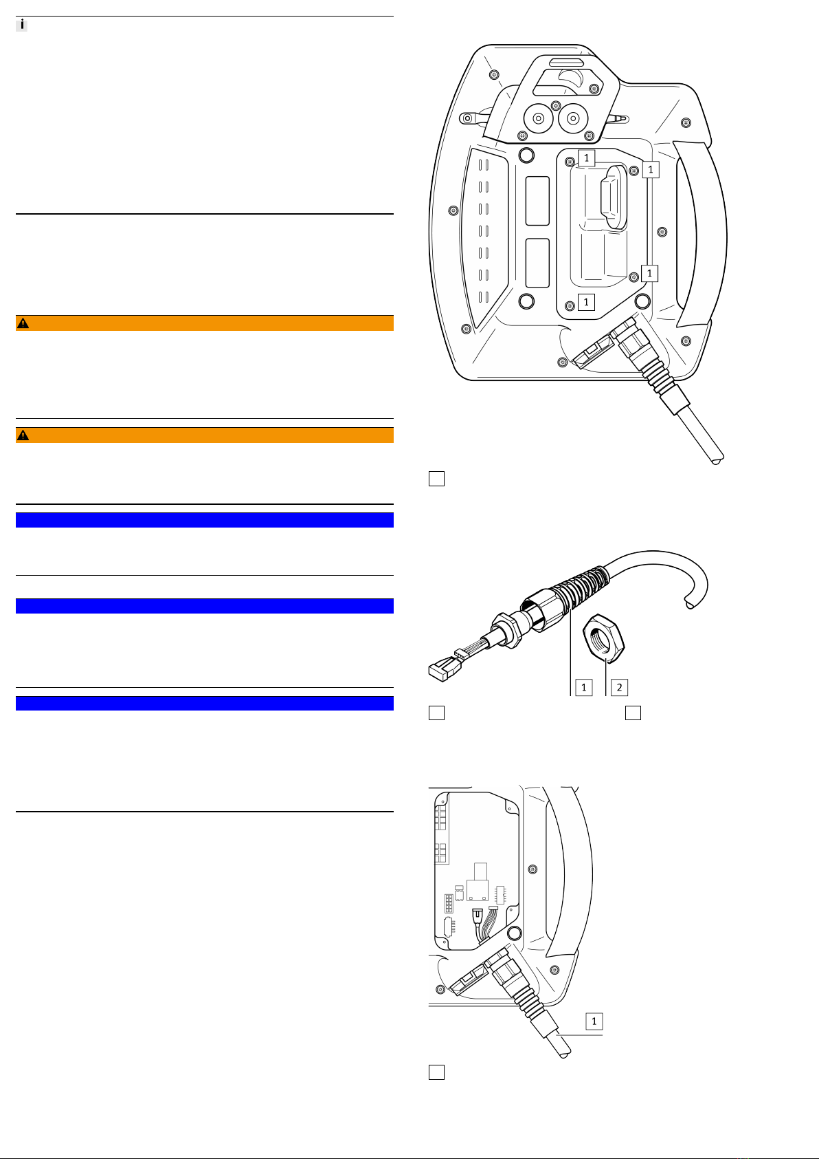
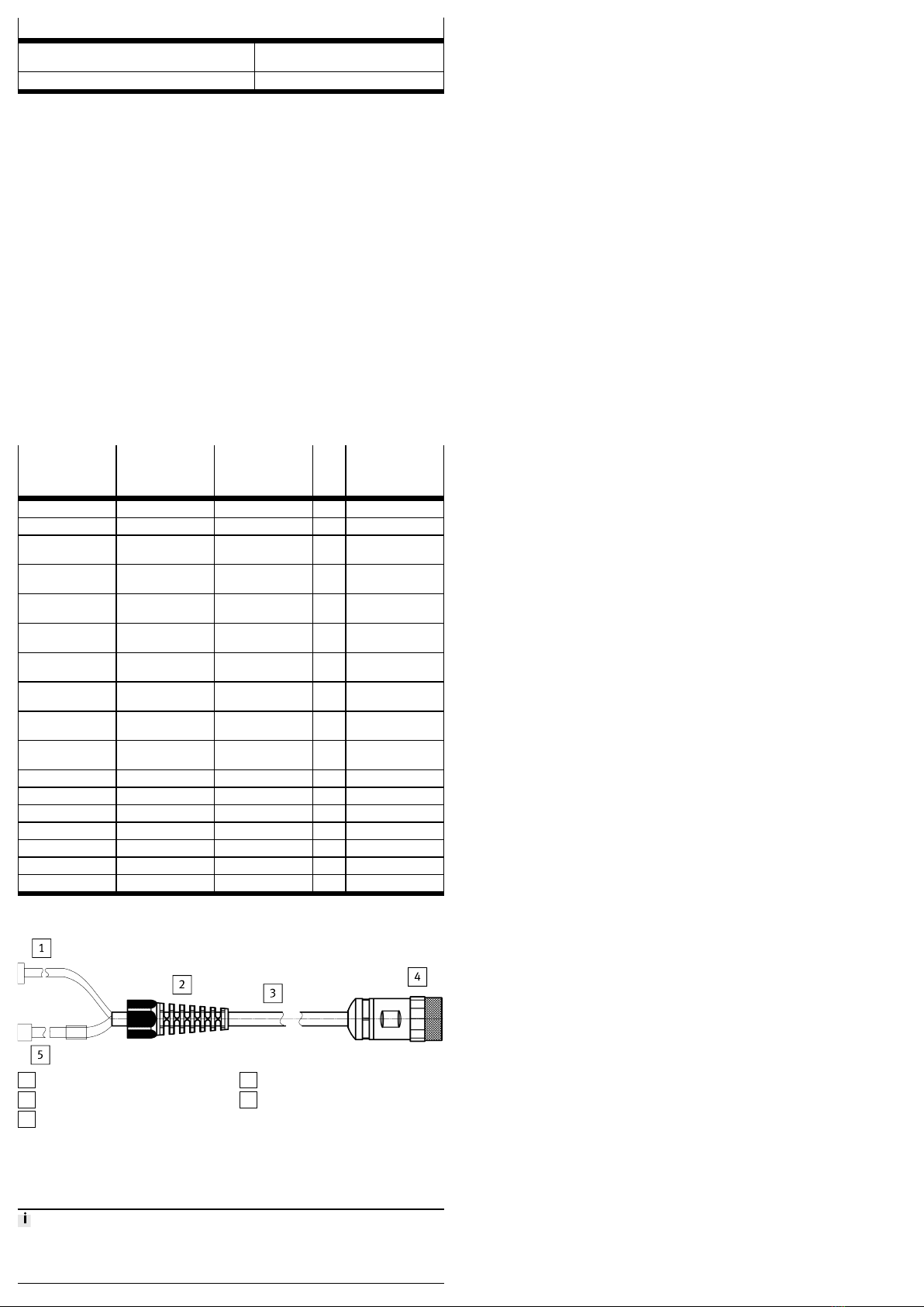
5. Fix the grommet with a size 19 spanner (torque: 3 Nm).
6. Insert the main plug and the RJ45 plug into the sockets provided for this pur
pose.
7. Tighten the strain relief with the spanner. Part of the cable sheath should be
located inside the housing. Make sure that the rubber ring for the strain relief
is correctly under the grommet.
8. Attach cover and screw in the TORX screws (torque: 0.8…1.0 Nm).
Unplug cable
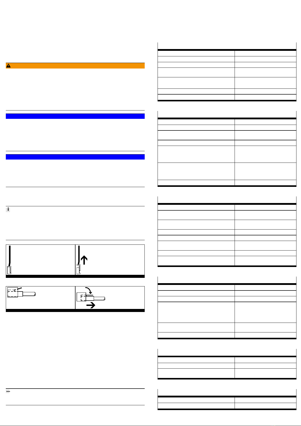
1. Pull the cable with your fingers to unplug the main plug.
2. To RJ45plug, actuate the locking lever.
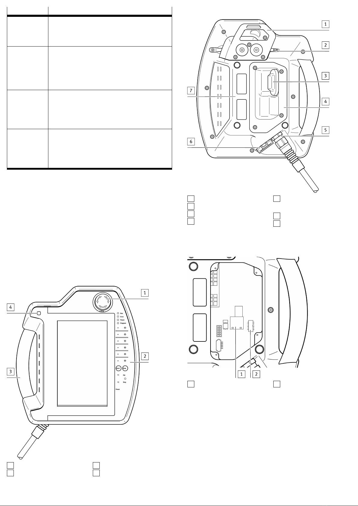
7.2 Cable installation in the connection shaft
WARNING!
Failure of the emergency stop or the enabling function.
Failure of the emergency stop or enabling functions can result in personal injury
and material damage.
• When plugging in, make sure that the main plug engages correctly.
• Check the emergency stop and enabling functions before recommissioning
the handheld terminal CDSAD3RV.
• Check the emergency stop and enabling functions before commissioning the
machine or system.
NOTICE!
Incorrect handling when closing the connection shaft.
Incorrect handling can damage the cables and the connection shaft.
• The seal must be clean, undamaged and in the correct position.
• Do not pinch the cable.
• Screw on the cover of the connection shaft with all screws and tighten to a
torque of 0.8 to 1.0Nm.
NOTICE!
Incorrect handling of the plug when working in the connection shaft.
Incorrect handling can damage the plugs and the socket.
• Do not use sharp objects to remove the plugs.
• Disconnect the main plug by pulling its wires with fingers.
• Press the locking lever to disconnect the RJ45 plug.
When the connection shaft is opened, the connecting cables can be positioned as
shown in the following sections. Before opening the handheld terminal
CDSAD3RV observe the following instructions:
Information for opening the connection shaft
• Place the handheld terminal CDSAD3RV with the display facing downwards
on a flat, clean and soft base so that the handheld terminal CDSAD3RV or its
operating elements are not damaged (e.g. ESD mat).
• To open and close the connection shaft, use a "TORX size 10" screwdriver.
Tab. 7 Unplugging the main plug
Tab. 8 Unplugging the RJ45 plug
8 Maintenance
9 Repair
Repair or maintenance of the product by unauthorised persons is not permitted;
this may invalidate the conformity of the product.
If necessary, replace the complete product.
– If a safety device is defective, the product must be replaced.
– In this case, send the defective product unchanged with a description of the
fault and application to Festo for analysis.
– Check with your regional Festo contact person to clarify the conditions for the
return shipment.
10 Disposal
ENVIRONMENT!
Dispose of the product and packaging according to the applicable provisions of
environmentally sound recycling.
10.1 Safety-related control elements
After expiry of the service life T10D, but no later than after 20 years, the safety
related control elements "Emergency stop device" and "3position enabling
switch" must be permanently disabled.
11 Technical data
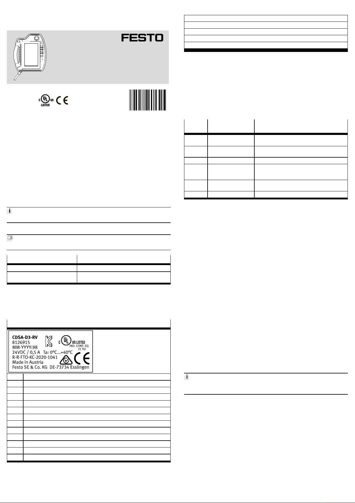
11.1 Handheld terminal CDSA-D3-RV
Emergency stop device
Nominal voltage (Ue) [VDC] 24
Minimum current (Ie) [mA] 10 (per contact)
Max. current rating [mA] 1,000 (per contact)
Utilisation category (in accordance with
IEC 6094751)
DC13
Schlegel FRVKOO
– B10D 250,000
Design twocircuit, external wiring
Electrical isolation [VAC] 500 to all other networks
Tab. 9 Emergency stop device
3-position enabling switch
Output type Electromechanical switching contact
Switchable nominal voltage (Ue) [VDC] 24
Nominal voltage tolerance range (in
accordance with EN 611312)
[VDC] 19.2…30
Max. nominal current (Ie) [mA] 500
B10D
– Switch setting 2 106
– Switch setting 3 106
Actuating forces
– From switch position 1 to 2 Typically 3 N
– From switch position 2 to 3 Typically 17 N
Electrical isolation [VAC] 500 to all other networks
Tab. 10 3position enabling switch
Technical data, general
Nominal voltage [VDC] 24
Nominal voltage tolerance range (in
accordance with EN 611312)
[VDC] 19.2…30
Max. interruption duration of the supply
voltage (in accordance with EN 611312)
[ms] £ 10
Max. starting current [A] 5.6 (current limitation available)
Power consumption [W] 12 (500mA at 24 V DC)
Protection class (in accordance with
EN 611312 and/or EN 50178)
III
Degree of protection IP65
CE certification See declaration of conformity
èwww.festo.com
Tab. 11 Technical data, general
Ambient conditions
Operating temperature [°C] 0…40
Storage temperature [°C] –25…70
Relative humidity (noncondensing) [%] 5…95
Vibration resistance (in accordance with
IEC 6006826)
– With 3.5 mm [Hz] 5 £ f < 8.4
– With 1g [Hz] 8.4 £ f < 150
Shock resistance (in accordance with
EN 611312)
[g/ms] 15/11
Max. operating altitude (sea level) [m] 2,000
Tab. 12 Ambient conditions
Mechanical characteristics
Design Housing made of ABS
Flammability UL94V0
Fallproof suitability [m] 1.5 (on industrial floor), then at least
degree of protectionIP54
Tab. 13 Mechanical characteristics
Dimensions, weight
Height [mm] 251
Width [mm] 212
Dimensions, weight
Depth (incl. handle and emergency stop
device)
[mm] 73
Weight [g] Approx. 950
Tab. 14 Dimensions, weight
11.1.1 Accessories
The product may only be operated with the accessories named in this chapter.
11.1.1.1 Wall bracket CAFM-D4-W
The powdercoated black wall bracket is used for stationary operation or for stor
ing the handheld terminal CDSAD3RV.
11.1.1.2 Interface housing CAMI-C
The interface housing CAMIC is used to connect a handheld terminal CDSAD3RV
to a controller with the connecting cable
NEBCR3Z12G20KH5NSBSRSG17ETS1.
Connection
This chapter describes the connection of the control cables (power supply, emer
gency stop and enabling circuits) and the data cables to the interface housing
è Fig.4.
11.1.1.3 Connecting cable NEBC-R3Z12G20-KH-xx-N-SBS-RSG17-ET-S1
The handheld terminal CDSAD3RV is available as standard with the following
connecting cables:
– NEBCR3Z12G20KH5NSBSRSG17ETS1: 5m
– NEBCR3Z12G20KH10NSBSRSG17ETS1: 10m
– NEBCR3Z12G20KH15NSBSRSG17ETS1: 15m
The connecting cable is resistant to water, cleaning agents (alcohols and deter
gents), oils, greases and lubricants.
Signal descrip-
tion
S2, 12-pin sock-
et connector
S3, 8-pin RJ45
plug
S1, 17-pin plug
connector, pin
no.
24 VDC 1 – → 1
GND_IN 2 – → 2
Emergency stop, cir
cuit 2
3 – → 3
Emergency stop, cir
cuit 2
4 – → 4
Emergency stop, cir
cuit 1
5 – → 5
Emergency stop, cir
cuit 1
6 – → 6
Enable control, cir
cuit 1, pos.
7 – → 7
Enable control, cir
cuit 1, neg.
8 – → 8
Enable control, cir
cuit 2, pos.
9 – → 12
Enable control, cir
cuit 2, neg.
10 – → 17
not used 11 – → 9
not used 12 – → 10
not used – – → 11
TD+ (Ethernet) – 1 → 13
TD– (Ethernet) – 2 → 14
RD+ (Ethernet) – 3 → 15
RD– (Ethernet) – 6 → 16
Tab. 15 Pin allocation
1S2  12pin socket plug
2K2  cable sleeve
3K1  connecting cable
4S1  17pin plug connector
5S3  8pin RJ45 plug
Fig. 10 Connecting cable
11.1.1.4 CAMF-B-M25-G4 jumper plug
The jumper plug is used to bypass the emergency stop circuit when the handheld
terminal is disconnected.
Foreseeable misuse of the jumper plug
The jumper plug must be removed before commissioning the hazardous machine
function.

Other manuals for CDSA-D3-RV

1

This manual suits for next models

1

Other Festo Touch Terminal manuals

Festo CPX-M-FB20 User manual

Festo

Festo CPX-M-FB20 User manual

Festo CPX-FB33 User manual

Festo

Festo CPX-FB33 User manual

Festo CPX-CMXX Parts list manual

Festo

Festo CPX-CMXX Parts list manual

Festo CPX-FB6 User manual

Festo

Festo CPX-FB6 User manual

Festo VTEM Operating and installation instructions

Festo

Festo VTEM Operating and installation instructions

Festo CPV E ASI-4E4A Series Parts list manual

Festo

Festo CPV E ASI-4E4A Series Parts list manual

Festo VIFB8-03 Series Parts list manual

Festo

Festo VIFB8-03 Series Parts list manual

Festo CPA VI-MP Series Parts list manual

Festo

Festo CPA VI-MP Series Parts list manual

Festo CPX-FB37 User manual

Festo

Festo CPX-FB37 User manual

Festo VTEM User manual

Festo

Festo VTEM User manual

Festo CPV-SC Series User manual

Festo

Festo CPV-SC Series User manual

Festo CPV10-GE-IBL-8 User manual

Festo

Festo CPV10-GE-IBL-8 User manual

Festo CPX-FB32 User manual

Festo

Festo CPX-FB32 User manual

Festo CPX-FB33 Reference guide

Festo

Festo CPX-FB33 Reference guide

Festo MPA1-MP Series User manual

Festo

Festo MPA1-MP Series User manual

Festo VTSA-F-CB Assembly instructions

Festo

Festo VTSA-F-CB Assembly instructions

Festo CDSA-D3-RV User manual

Festo

Festo CDSA-D3-RV User manual

Festo IFB11-03 User manual

Festo

Festo IFB11-03 User manual

Festo CPX-CEC User manual

Festo

Festo CPX-CEC User manual

Festo VTSA ASI-8E8A-Z Series Parts list manual

Festo

Festo VTSA ASI-8E8A-Z Series Parts list manual

Festo FB13 User manual

Festo

Festo FB13 User manual

Festo CPX-...DE Series User manual

Festo

Festo CPX-...DE Series User manual

Festo VTSA-44-MP Series User manual

Festo

Festo VTSA-44-MP Series User manual

Festo CPX-FB13 User manual

Festo

Festo CPX-FB13 User manual

Popular Touch Terminal manuals by other brands

Fametech Zircon Series user manual

Fametech

Fametech Zircon Series user manual

ZKTeco SpeedFace - V5L quick start guide

ZKTeco

ZKTeco SpeedFace - V5L quick start guide

Sagem MORPHOACCESS 200 installation guide

Sagem

Sagem MORPHOACCESS 200 installation guide

Casio QT-6600 Programming manual

Casio

Casio QT-6600 Programming manual

POSIFLEX PST-1000 Series Technical manual

POSIFLEX

POSIFLEX PST-1000 Series Technical manual

Datecs BluePad-50 Plus MSR user guide

Datecs

Datecs BluePad-50 Plus MSR user guide

Altos IV user guide

Altos

Altos IV user guide

Mitsubishi Electric E1032 installation manual

Mitsubishi Electric

Mitsubishi Electric E1032 installation manual

Glonex MVT100 installation guide

Glonex

Glonex MVT100 installation guide

First Data VX820 Duet Quick reference guide

First Data

First Data VX820 Duet Quick reference guide

POSMicro POS-X EVO-TP4 Pro user manual

POSMicro

POSMicro POS-X EVO-TP4 Pro user manual

Opticon PHL-7100 user manual

Opticon

Opticon PHL-7100 user manual

FingerTec TA500 user guide

FingerTec

FingerTec TA500 user guide

Castles Technology VEGA3000 user manual

Castles Technology

Castles Technology VEGA3000 user manual

Siemens 3VT9100-4RC00 operating instructions

Siemens

Siemens 3VT9100-4RC00 operating instructions

Honeywell SP5600-C OptimusR user manual

Honeywell

Honeywell SP5600-C OptimusR user manual

elrest eVISIO PTE715 Device description

elrest

elrest eVISIO PTE715 Device description

Clover Station Solo quick start guide

Clover

Clover Station Solo quick start guide

manuals.online logo
manuals.online logoBrands
  • About & Mission
  • Contact us
  • Privacy Policy
  • Terms and Conditions

Copyright 2025 Manuals.Online. All Rights Reserved.