Before reading this manual
3
1. Read Instructions
All the safety and operating instructions should be read before the appliance
is operated.
2. Retain Instructions
The safety and operating instructions should be retained for future reference.
3. Cleaning
Unplug this equipment from the wall outlet before cleaning it. Do not use
liquid aerosol cleaners. Use a damp soft cloth for cleaning.
4. Attachments
Never add any attachments and/or equipment without the approval of the
manufacturer as such additions may result in the risk of re, electric shock or
other personal injury.
5. Water and/or Moisture
Do not use this equipment near water or in contact with water.
6. Ventilation
Place this equipment only in an upright position. This equipment has an
open-frame Switching Mode Power Supply (SMPS), which can cause a re or
electric shock if anything is inserted through the ventilation holes on the side
of the equipment.
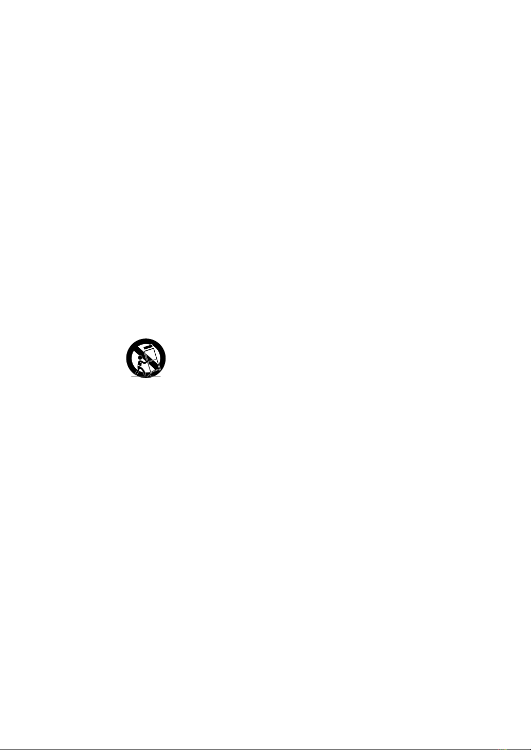
7. Accessories
Do not place this equipment on an unstable cart, stand or table. The
equipment may fall, causing serious injury to a child or adult, and serious
damage to the equipment. Wall or shelf mounting should follow the
manufacturer's instructions, and should use a mounting kit approved by the
manufacturer.
This equipment and cart combination should be moved with care. Quick
stops, excessive force, and uneven surfaces may cause the equipment and cart
combination to overturn.
8. Power Sources
This equipment should be operated only from the type of power source
indicated on the marking label. If you are not sure of the type of power, please
consult your equipment dealer or local power company. You may want to
install a UPS (Uninterruptible Power Supply) system for safe operation in order
to prevent damage caused by an unexpected power stoppage. Any questions
concerning UPS, consult your UPS retailer.
This equipment should be remain readily operable.
9. Power Cords
Operator or installer must remove power and TNT connections before
handling the equipment.
10. Lightning
For added protection for this equipment during a lightning storm, or when it
is left unattended and unused for long periods of time, unplug it from the wall
outlet and disconnect the antenna or cable system. This will prevent damage
to the equipment due to lightning and power-line surges.
11. Overloading
Do not overload wall outlets and extension cords as this can result in the risk
of re or electric shock.
12. Objects and Liquids
Never push objects of any kind through openings of this equipment as they
may touch dangerous voltage points or short out parts that could result in a
re or electric shock. Never spill liquid of any kind on the equipment.
13. Servicing
Do not attempt to service this equipment yourself. Refer all servicing to
qualied service personnel.
14. Damage requiring Service
Unplug this equipment from the wall outlet and refer servicing to qualied
service personnel under the following conditions:
A. When the power-supply cord or the plug has been damaged.
B. If liquid is spilled, or objects have fallen into the equipment.
C. If the equipment has been exposed to rain or water.
D. If the equipment does not operate normally by following the operating
instructions, adjust only those controls that are covered by the operating
instructions as an improper adjustment of other controls may result in
damage and will often require extensive work by a qualied technician to
restore the equipment to its normal operation.
E. If the equipment has been dropped, or the cabinet damaged.
F. When the equipment exhibits a distinct change in performance ─this
indicates a need for service.
15. Replacement Parts
When replacement parts are required, be sure the service technician has
used replacement parts specied by the manufacturer or that have the same
characteristics as the original part. Unauthorized substitutions may result in
re, electric shock or other hazards.
16. Safety Check
Upon completion of any service or repairs to this equipment, ask the service
technician to perform safety checks to determine that the equipment is in
proper operating condition.
17. Field Installation
This installation should be made by a qualied service person and should
conform to all local codes.
18. Correct Batteries
Warning: Risk of explosion if battery is replaced by an incorrect type. Replace
only with the same or equivalent type. Dispose of used batteries according to
the instructions. The battery shall not be exposed to excessive heat such as
sunshine, re or the like.
Avertissement: risque d'explosion en cas d'utilisation d'une batterie de type
incorrect. Le remplacer uniquement par un type identique ou équivalent.
Mettre les batteries usées au rebut conformément aux instructions. La batterie
ne doit pas être exposée à une source de chaleur excessive, telle que le soleil,
le feu, ou analogue.
19. Tmra
A manufacturer’s maximum recommended ambient temperature (Tmra)
for the equipment must be specied so that the customer and installer may
determine a suitable maximum operating environment for the equipment.
20. Elevated Operating Ambient Temperature
If installed in a closed or multi-unit rack assembly, the operating ambient
temperature of the rack environment may be greater than room ambient.
Therefore, consideration should be given to installing the equipment in an
environment compatible with the manufacturer’s maximum rated ambient
temperature (Tmra).
21. Reduced Air Flow
Installation of the equipment in the rack should be such that the amount of
airow required for safe operation of the equipment is not compromised.
22. Mechanical Loading
Mounting of the equipment in the rack should be such that a hazardous
condition is not caused by uneven mechanical loading.
23. Circuit Overloading
Consideration should be given to connection of the equipment to supply
circuit and the eect that overloading of circuits might have on over current
protection and supply wiring. Appropriate consideration of equipment
nameplate ratings should be used when addressing this concern.
24. Reliable Earthing (Grounding)
Reliable grounding of rack mounted equipment should be maintained.
Particular attention should be given to supply connections other than direct
connections to the branch circuit (e.g., use of power strips).