IDK HDC-RH401 User manual

HDC-RH401/201/101 Users Guide
1
HDBaseT Daisy Chain Receiver & HDMI Splitter
HDC-RH401/201/101
<User’s Guide>
Ver.1.5.0
•Thank you for choosing our product.
•To ensure the best performance of this product, please read this User’s Guide fully and carefully before
using it and keep this manual beside this product.
IDK Corporation
HDC-RH401
ON
OFF
Cat6 RECEIVER with HDMI O UTPUTS
POWER
AC90-250V
HDC INPUT OUTPUT 1
LINK
HDC OUTPUT OUTPUT 2
OUTPUT 3 OUTPUT 4
SIGNAL LINK
UPDATE
FG
S/N
HDMI/DVI
HDMI/DVI
HDMI/DVI
HDMI/DVI

HDC-RH401/201/101 Users Guide
2
Trademarks
●Blu-ray Disc and Blu-ray are trademarks of Blu-ray Disc Association.
●The terms HDMI and HDMI High-Definition Multimedia Interface, and the HDMI Logo are trademarks or
registered trademarks of HDMI Licensing, LLC in the United States and other countries.
●PJLink is a trademark in Japan, the United States, and other countries/regions.
●HDBaseT™ and the HDBaseT Alliance Logo are trademarks of the HDBaseT Alliance.
●Microsoft, Windows, Internet Explorer are either registered trademarks or trademarks of the Microsoft
Corporation in the United States and other countries.
●ETHERNET is registered trademark of Fuji Xerox Corporation.
●Mozilla, Firefox and its logo are trademarks or registered trademarks of the Mozilla Foundation in the
United States and other countries.
●Google Chrome is trademark or registered trademark of Google Inc.
●Javascript® is trademark or registered trademark of the Oracle Corporation and its related companies in
the United States and other countries.
●Oracle and Java are registered trademarks of the Oracle Corporation and its related companies in the
United States and other countries.
●All other company and product names mentioned in this manual are either registered trademarks or
trademarks of their respective owners. In this manual, the “®” or “™” marks may not be specified.

HDC-RH401/201/101 Users Guide
3
All rights reserved.
Some of the contents in this User’s Guide such as appearance diagrams, menu operations,
communication commands, and so on may differ depending on the version.
This User’s Guide is subject to change without notice. You can download the latest version from IDK’s
website at: http://www.idk.co.jp/en/index.html
FCC STATEMENT
This equipment has been tested and found to comply with the limits for a Class A digital device, pursuant to
part 15 of the FCC Rules. These limits are designed to provide reasonable protection against harmful
interference when the equipment is operated in a commercial environment. This equipment generates, uses,
and can radiate radio frequency energy and, if not installed and used in accordance with the instruction
manual, may cause harmful interference to radio communications. Operation of this equipment in a residential
area is likely to cause harmful interference, in which case the user will be required to correct the interference
at his own expense.
Note: This equipment was tested with shielded cables on the peripheral devices. Shielded cables must be
used with the equipment to ensure compliance with FCC emissions limits.
CE MARKING
This equipment complies with the essential requirements of the relevant European health, safety and
environmental protection legislation.
WEEE MARKING
Waste Electrical and Electronic Equipment (WEEE), Directive 2002/96/EC
(This directive is only valid in the EU).
This equipment complies with the WEEE Directive (2002/96/EC) marking requirement.
The left marking indicates that you must not discard this electrical/electronic equipment in
domestic household waste.
This equipment complies CISPR 22/EN 55022, VCCI, and FCC Part 15 Subpart B standards. To comply
these standards, please use Ferrite Core to 5 cm from cable connector.
Before reading this manual
The lasers in this product meet Class 1 Laser Safety per FDA/CDRH and
EN (IEC) 60825 laser safety standards which specify design safety.
クラス 1 レーザ製品
CLASS 1 LASER PRODUCT

HDC-RH401/201/101 Users Guide
4
Safety instructions
Read and understand all safety and operating instructions before using this device. Follow all instructions and
cautions as detailed in this document.
Enforcement Symbol
Description
Indicates the presence of a hazard that may result in death or serious
personal injury if the warning is ignored or the equipment is handled
incorrectly.
Indicates the presence of a hazard that may cause minor personal
injury or property damage if the caution is ignored or the equipment is
handled incorrectly.
Symbol
Description
Example
Caution
This symbol is indicated to alert the user. (Warning and caution)
Electrical
Hazard
Prohibition
This symbol is intended to prohibit the user from actions.
Do not
disassemble
Instruction
This symbol is intended to instruct the user.
Unplug
Caution
Warning

HDC-RH401/201/101 Users Guide
5
Prohibition
Do not place the product in any unstable place.
Install the product to a horizontal and stable place. Otherwise, it may fall/turn over and lead to injury.
Do not place the product in any environment with vibration.
Otherwise, it may move/fall and lead to injury.
Keep out any foreign objects.
In order to avoid fire or electric shock, do not allow foreign objects, such as metal and paper, to enter the product
from the vent holes.
For power cable/ plug:
・Do not scratch, heat, or modify, including extending them.
・Do not pull, put heavy stuff on them, or pinch them.
・Do not bend, twist, or tie them together forcefully.
If they are used in those states continuously, it may cause fire or electric shock. If power cables/plugs become
damaged, contact IDK.
Do not
disassemble
Do not repair, modify or disassemble.
Since the product includes high-voltage parts, those actions may cause fire or electric shock. For internal
inspections or repairs, contact IDK.
Do not touch
In the event of lighting or thunder, do not touch the main unit or cables such as
power cable and LAN cable.
Contact may cause electric shock
Instruction
For installation:
The product is intended to be installed by skilled technicians. For installation, please contact a system integrator
or IDK. Otherwise, it may cause fire, electric shock, injury, or property damage.
Set the power plug in a convenient place to unplug easily.
You can easily unplug in case of any extraordinary failure or abnormal situation, and it also helps for unplugging
when you do not use it for a long period.
Plug the power plug into appropriate outlet completely.
If the plug is plugged incompletely, it may overheat which causes electrical shock or fire. Do not use damaged
plug or loosened outlet.
Clean the power plug regularly.
If the plug is covered in dust, it may cause fire due to reduced insulating power.
Unplug
Unplug immediately if the product smokes, makes unusual noise, or smells.
If you continue to use the product under those situations, it may cause electric shock or fire. After confirming that
the product stops smoking, contact IDK.
Unplug immediately if you drop the product or if the cabinet is damaged.
If you continue to use the product under those situations, it may cause electrical shock or fire. For maintenance
and repair, contact IDK.
Unplug immediately if water or other objects are directed inside.
If you continue to use it under those situations, it may cause electrical shock or fire. For maintenance and repair,
contact IDK.
For connection
Instruction
Differences in ground potential among the product and peripheral devices may cause electric shock or damage
of the devices. When using cables to connect devices, including connection of long-distance transmission,
unplug the power cables of all related devices.
After connecting signal/control cables of each device, plug in the power cables of each device.
Warning

HDC-RH401/201/101 Users Guide
6
For installation
For rack mount devices:
Instruction
Mount the product to the rack meeting EIA standards, and maintain spaces above and
below for air cooling. For your safety, attach an L-shape bracket in addition to the mount
bracket kit for the front panel in order to balance the weight.
For devices with rubber feet:
Instruction
Never insert only the screws into the holes after removing the rubber feet. It may lead to
damage when the screws contact electrical circuit or parts inside of the product.
To put the rubber feet back on, use only provided rubber feet and screws.
Prohibition
Do not place the product in any place where it will be subjected to high
temperatures.
If the product is subjected to direct sunlight or high temperatures, it may cause fire.
Do not place the product in humid, oil smoke, or dusty place.
If the product is placed near humidifiers or dusty area, it may cause fire or electric shock.
Do not block the vent holes.
If ventilation slots are blocked, it may cause fire or failure due to internal heat.
Do not put heavy items on the product.
It may fall/turn over and lead to injury.
Do not exceed ratings of outlet and wiring devices.
If several plugs are put in an outlet, it may cause fire and electric shock.
Use only the provided AC adapter and power cable.
If non-compliant adapter or power cables is used, it may cause fire or electrical shock. Use the provided AC
power connection cable. If you want to use your product in other countries that use
different AC power cables,
contact IDK.
No wet hands
Do not plug or unplug with wet hands.
It may cause electrical shock.
Instruction
Use and store the product within the specified temperature/humidity range.
If the product is used outside the range continuously, it may cause fire or electric shock.
Turn off devices when they are connected to another device.
It may cause fire or electric shock.
Unplug
Unplug the power plug if you do not use the product for a long period.
In case of defect, it may cause fire.
Unplug the power plug before cleaning.
It may cause electric shock.
Caution

HDC-RH401/201/101 Users Guide
7
Altitude:
Instruction
Do not place the product at elevations of 2,000 meters (6562 feet) or higher above sea
level. Failure to do so may shorten the life of the internal parts and result in malfunctions.

HDC-RH401/201/101 Users Guide
8
Table of Contents
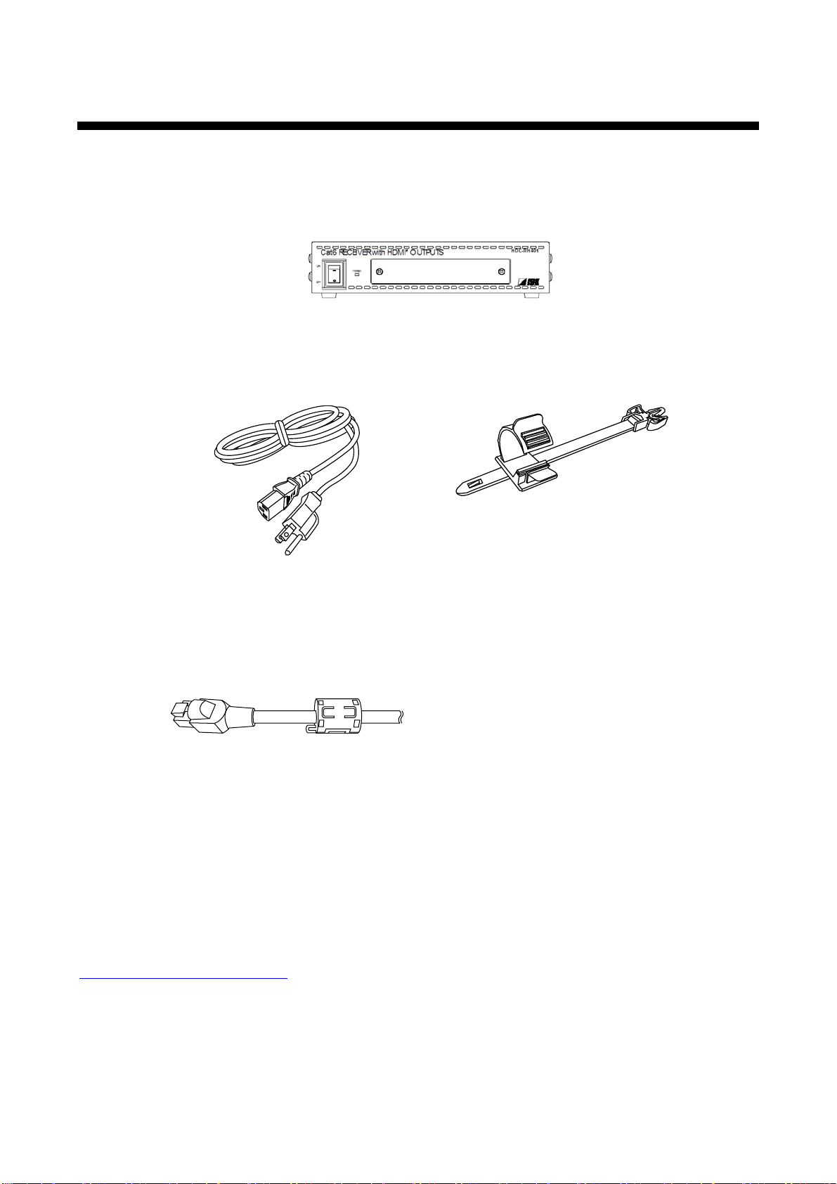
1Included items......................................................................................................................................10
2Product outline.....................................................................................................................................11
3Features..............................................................................................................................................12
4Panels .................................................................................................................................................13
4.1 Front panel ...................................................................................................................................13
4.2 Rear panel....................................................................................................................................14
5Example connection.............................................................................................................................16
6Precautions..........................................................................................................................................17
6.1 Installation ....................................................................................................................................17
6.2 Cabling.........................................................................................................................................18
6.2.1 Cables..........................................................................................................................................19
6.2.2 Twisted pair cable.........................................................................................................................19
7Basic operation....................................................................................................................................21
7.1 Menu operation keys.....................................................................................................................21
7.2 Initialization...................................................................................................................................22
7.3 Notes on use.................................................................................................................................23
8Menus..................................................................................................................................................24
8.1 Menu operation.............................................................................................................................24
8.2 Menu list.......................................................................................................................................25
8.3 [ F01 to F03 ] Copying EDID.........................................................................................................27
8.4 [ F10 ] Setting EDID resolution......................................................................................................29
8.5 [ F12 ] Setting external EDID.........................................................................................................31
8.6 [ F14 ] setting Copy EDID..............................................................................................................32
8.7 [ F16 ] Setting No-signal input monitoring time of Video signal.......................................................33
8.8 [ F20 ] Setting Deep Color.............................................................................................................35
8.9 [ F22 ] Setting PCM Audio.............................................................................................................36
8.10 [ F24 ] Setting AC-3 / Dolby Digital Audio.......................................................................................37
8.11 [ F26 ] Setting AAC Audio..............................................................................................................38
8.12 [ F28 ] Setting Dolby Digital + Audio..............................................................................................39
8.13 [ F30 ] Setting DTS Audio..............................................................................................................40
8.14 [ F32 ] Setting DTS-HD Audio........................................................................................................41
8.15 [ F34 ] Setting Dolby TrueHD Audio...............................................................................................42

HDC-RH401/201/101 Users Guide
9
8.16 [ F36 ] Setting Audio channel.........................................................................................................43
8.17 [ F38 ] Setting CEC physical address copy of EDID.......................................................................45
8.18 [ F65 to F69 ] Setting audio output ON/OFF ..................................................................................46
8.19 [ F75 ] Selecting CEC....................................................................................................................46
8.20 [ F76] Selecting EDID for WXGA...................................................................................................47
8.21 [ F90 ] Displaying firmware version................................................................................................48
8.22 [ F99 ] Setting maintenance/status display menu...........................................................................49
8.23 [ C01 to C05] Setting forced output HDMI mode............................................................................50
8.24 [ C06 ] Setting HDCP input............................................................................................................51
8.25 [ C10 ] Setting how long video output requests of sink device are ignored .....................................52
8.26 [ C55 to C59 ] Setting output color conversion manually................................................................53
8.27 [ L01 to L69] Displaying status ......................................................................................................54
9Specification........................................................................................................................................60
9.1 Product specification.....................................................................................................................60
9.2 HDMI Type A connector.................................................................................................................62
9.3 RJ-45 connector pin assignment...................................................................................................62
10 Trouble shooting..................................................................................................................................63

HDC-RH401/201/101 Users Guide
10
1 Included items
Make sure all items below are included in the package.
If any items are missing or damaged, please contact IDK.
One (1) HDBaseT Daisy Chain Receiver & HDMI Splitter (main unit)
One (1) power cord
(1.8 meters; approximately 5.91 feet)
Cord clamps
One (1) for HDC-RH101
Two (2) for HDC-RH201
Four (4) for HDC-RH401
Two (2) Ferrite Core
[Fig. 1.1] Included items
You can download the latest version of the User’s Guide from IDK’s website at:
http://www.idk.co.jp/en/index.html

HDC-RH401/201/101 Users Guide
11
2 Product outline
The IDK HDC-RH101, 201, and 401 are receivers for HDBaseT signal. HDC-RH101, 201, and 401 have
HDBaseT daisy chain and HDMI signal splitter functions. By using with the IDK HDC series transmitters,
video and audio signals can be extended and distributed to up to four HDMI devices at receiver side.
Blu-ray Disc player HDC-TD100-B
HDC-TH100-C
Cat6 cable
Up to 197 ft. / 60 m
Transmitter
HDC-RD100-B
Projector
Receiver Monitor
HDC-TH401
ON
OFF
Cat6 TRANSMITTERwith HDMI INPUT
POWER
HDC-TH401/201/101
HDC-RH401
ON
OFF
C at 6 REC EIVER w it h H D MI O U TPUTS
POWER
HDC-RH401/201/101 HDMI (HDCP)
Monitor
HDC-S400
ON
OFF
Cat6 SPLITTER
POWER
HDC-S400/200
Cat6 cable
Distribution Amplifier
Distribution
Cat6 cable
Up to 197 ft. / 60 m
Laptop PC
or
Monitor
HDC-RH100-C
Receiver
HDMI (HDCP)
DVI (HDCP)
HDMI (HDCP)
HDMI (HDCP)
Up to 17 ft. / 5 m
DVI (HDCP)
Up to 17 ft. / 5 m
Up to 17 ft. / 5 m
Up to 17 ft. / 5 m
Up to 17 ft. / 5 m
Up to 17 ft. / 5 m
*
*
*
*
* Up to 7 ft. / 2m : HDC-TH100-C or HDC-RH100-C
RS-232CLAN
Tx
Cat6 Txfor HDM I
POWER LINK HDCP
STATUS
POWER LINK HDCPPOWER LINK HDCP
STATUS
INPUT
(MAX2M)
OUTPUTFG DC 5V 2A
DON'T
CONNECT
LAN
HDC-TH100-C
HDBaseT
CAUTION
!
HDMI
OUTPUT
RS-232C
FG DC 5V 3A
CAUTION
!
DON'T
CONNECT
LAN
L
AUDIOOUTPUT
R
POWER
STATUS
LINK HDCP
LAN
SIGNAL
DVIINPUT
Tx
Cat6 Txfo r DVI
HDC-TD100-B
HDBaseT
(HDCP)
Rx
RS-232CLAN
Cat6 Rxfor HDMI
POWER LINK HDCP
STATUS
POWER LINK HDCPPOWER LINK HDCP
STATUS
FG DC5V 2A
HDC-RH100-C
INPUT
DON'T
CONNECT
LAN
HDBaseT
CAUTION
!
(MAX2M)
HDMI
OUTPUT
INPUT
RS-232C
FG DC 5V 3A
CAUTION
DON'T
CONNECT
LAN
Rx
Cat6 Rxfor DVI
HDC-RD100-B
POWER
STATUS
LINK HDCP
LAN
SIGNAL
DVIOUTPUT
!
HDBaseT
(HDCP)
[Fig. 2.1] HDC-RH401/201/101 diagram

HDC-RH401/201/101 Users Guide
12
3 Features
■ Video
Up to QWXGA (RB)*1 or 1080p
HDCP supported
Up to 197 ft. approx. / 60 m signal extension over a Cat6 cable
Daisy chain connection
Anti-snow
■ Others
EDID emulation
Seven segment LED signal status check
Connection Reset (only HDMI output)
*1. (RB) = Reduced Blanking

HDC-RH401/201/101 Users Guide
13
4 Panels
4.1 Front panel
HDC-RH401
ON
OFF
Cat6 RECEIVER with HDMI O UTPUTS
POWER
①②
[Fig. 4.1] Front panel drawing (HDC-RH401/201/101)
# Part name Description
①Power supply switch
(POWER)
Turns on/off the HDC
The POWER LED lights when the HDC is turned on.
②
Segment display and
menu operation keys
Sets menu using “SET”, “+”, and “-“ keys.
(The cover plate with access to the menu is removable.)
【See “7.1 Menu operation”】
Note: Front panels for HDC-RH401/201/101 are common.

HDC-RH401/201/101 Users Guide
14
4.2 Rear panel
HDC-RH401
②
①③⑤
④⑥⑦⑨
⑧
AC90-250V
HDC INPUT OUTPUT 1
LINK
HDC OUTPUT OUTPUT 2
OUTPUT 3 OUTPUT 4
SIGNAL LINK
UPDATE
FG
S/N
HDMI/DVI
HDMI/DVI
HDMI/DVI
HDMI/DVI
HDC-RH201
②① ③⑤
④⑥ ⑦ ⑨
⑧
AC90-250V
HDC INPUT OUTPUT 1
LINK
HDC OUTPUT OUTPUT 2
SIGNAL LINK
UPDATE
FG
S/N
HDMI/DVI
HDMI/DVI
HDC-RH401
②① ③ ⑤
④ ⑥ ⑦⑨
⑧
AC90-250V
HDC INPUT OUTPUT 1
LINK
HDC OUTPUT
SIGNAL LINK
UPDATE
FG
S/N
HDMI/DVI
[Fig 4.2] Panel drawing

HDC-RH401/201/101 Users Guide
15
# Part name Description
①SIGNAL LED ( SIGNAL ) The LED lights when video signal input the HDC.
②
Twisted pair input connector
(HDC INPUT)
Digital (video/audio) signals can be extended up to 60 m/197 ft.
using the HDC transmitter.
③
LINK LED ( LINK )
The LED lights when HDC transmitter is connected.
④Twisted pair output connector
(HDC OUTPUT)
Digital (video/audio) signals can be extended up to 60 m/197 ft.
using the HDC receiver.
⑤
LINK LED ( LINK )
The LED lights when HDC receiver is connected.
⑥
HDMI output
connector(OUTPUT1 to 4)
Output connector for HDMI signal.
Connector for sink devices such as LCD monitors and projectors
HDC-RH401 : four (4) outputs OUTPUT1 to 4
HDC-RH201 : two (2) outputs OUTPUT1 and 2
HDC-RH101 : one (1) output OUTPUT1
⑦Connector for Maintenance
( UPDATE ) Not used. Please do not connect anything; this connector is for
maintenance only.
⑧
Frame ground (FG)
An M3 screw is used.
Ground for indoor ground terminal.
⑨AC connector ( AC90-250V ) Connector for supplied AC cable.

HDC-RH401/201/101 Users Guide
16
5 Example connection
Blu-ray Disc player HDC-TD100-B
HDC-TH100-C
Cat6 cable
Up to 197 ft. / 60 m
Transmitter
HDC-RD100-B
Projector
Receiver Monitor
HDC-TH401
ON
OFF
Cat6 TRANSMITTERwith HDMI INPUT
POWER
HDC-TH401/201/101
HDC-RH401
ON
OFF
C at 6 REC EIVER w it h H DM I O U TPUTS
POWER
HDC-RH401/201/101 HDMI (HDCP)
Monitor
HDC-S400
ON
OFF
Cat6 SPLITTER
POWER
HDC-S400/200
Cat6 cable
Distribution Amplifier
Distribution
Cat6 cable
Up to 197 ft. / 60 m
Laptop PC
or
Monitor
HDC-RH100-C
Receiver
HDMI (HDCP)
DVI (HDCP)
HDMI (HDCP)
HDMI (HDCP)
Up to 17 ft. / 5 m
DVI (HDCP)
Up to 17 ft. / 5 m
Up to 17 ft. / 5 m
Up to 17 ft. / 5 m
Up to 17 ft. / 5 m
Up to 17 ft. / 5 m
*
*
*
*
* Up to 7 ft. / 2m : HDC-TH100-C or HDC-RH100-C
RS-232CLAN
Tx
Cat6 Txfor HDMI
POWER LINK HDCP
STATUS
POWER LINK HDCP
POWER LINK HDCP
STATUS
INPUT
(MAX2M)
OUTPUTFG DC 5V 2A
DON'T
CONNECT
LAN
HDC-TH100-C
HDBaseT
CAUTION
!
HDMI
OUTPUT
RS-232C
FG DC 5V 3A
CAUTION
!
DON'T
CONNECT
LAN
L
AUDIOOUTPUT
R
POWER
STATUS
LINK HDCP
LAN
SIGNAL
DVIINPUT
Tx
Cat6 Txfo r DVI
HDC-TD100-B
HDBaseT
(HDCP)
Rx
RS-232C
LAN
Cat6 Rxfor HDMI
POWER LINK HDCP
STATUS
POWER LINK HDCP
POWER LINK HDCP
STATUS
FG DC5V 2A
HDC-RH100-C
INPUT
DON'T
CONNECT
LAN
HDBaseT
CAUTION
!
(MAX2M)
HDMI
OUTPUT
INPUT
RS-232C
FG DC 5V 3A
CAUTION
DON'T
CONNECT
LAN
Rx
Cat6 Rxfor DVI
HDC-RD100-B
POWER
STATUS
LINK HDCP
LAN
SIGNAL
DVIOUTPUT
!
HDBaseT
(HDCP)
[Fig. 5.1] Sample system diagram

HDC-RH401/201/101 Users Guide
17
6 Precautions
Before connecting to external devices, follow the precautions below.
6.1 Installation
When installing the HDC, please observe the following precautions.
・Do not place the HDC on top of another HDC.
・Do not block vent holes. Please secure the space above ambient 30 mm/1.18 inches.
・Do not install the HDC to an enclosed space. When the HDC needs to be installed to EIA rack mount or
an enclosed space, please prepare ventilating equipment to keep the ambient temperature at 40 degrees
C/104 degrees F or less. If inadequately vented, the life of parts may be shortened and operations may be
affected.

HDC-RH401/201/101 Users Guide
18
6.2 Cabling
When connecting the HDC to the external devices, please observe the following precautions.
・Read manuals of the external devices.
・Before you connect the cable to the HDC or an external device, please remove electrification of the body
by touching the metal around that is grounded.
・Turn off all devises’ power before connecting the cable.
・Be sure to plug cables completely and install them without any stress on connectors.
・Fix HDMI cables using cable clamps to prevent those cables from falling off.
Fixing HDMI cable using cable clamp
Removing HDMI cable and cable clamp
①②③
Pull out while pressing
④
② ④ ⑤
①③
[Fig. 6.1] Attaching a cable clamp
■Connecting twisted pair cables
This equipment complies CISPR 22/EN 55022, VCCI, and FCC Part 15 Subpart B standards.
To comply these standards, please use Ferrite Core to 5 cm from cable connector.
HDC-RH401/201/101

HDC-RH401/201/101 Users Guide
19
6.2.1 Cables
IDK Corporation provides various digital cables such as HDMI, DVI, and twisted pair cables.
Please choose appropriate cables for your system configuration. For analog audio and RS-232C, please use
on processing the cable to fit the connectors.
6.2.2 Twisted pair cable
When connecting twisted pair cables to the HDC, please observe the following precautions.
・Cat5e/Cat6 UTP/STP can be used, however, we recommend a CAT.5E HDC cable* for the twisted pair
cable which is developed by IDK to maximize quality of video transmission.
・If using an STP cable, connect the FG connector to an earth ground source. Otherwise, the shielding
feature does not work correctly. When using a UTP cable, we still recommend using the ground
connector.
・The shielded STP cables are less affected by interference or external noise than UTP cables.
・The connector for twisted pair cable is as same as the connectors which are used for Ethernet (8 core
modular type connector), however, it cannot be connected and use for Ethernet because the way of data
transmission is different.
・The maximum extension distance of Cat5e/Cat6 UTP/STP cable is the shorter maximum extension
distance of the connected HDC receiver and sink device.
・For pin assignments, apply T568A or T568B standards for straight through wiring.
・Do not give connection cables a strong pull. The allowable tension of the twisted pair cable is 110 N.
・Do not bend the connection cable at a sharp angle. Keep the bend radius four times of the cable
diameter or longer.
・Do not tie the cable tightly; leave a space allowing the cable to move slightly.
・If you use the same cables, we recommended keeping a distance between the cables or not to place the
cables closely in parallel.
・Keep the twisted pair cable as straight as you can. If you coil the cable, it is easily affected by noise.
・Do not place this product in an electrically noisy environment, since high-speed signal is transmitted.
Particularly when you use a high-output radio around this device, video or audio may be interrupted.
・If the distance between the transmitter and receiver is 100 m/328.08 feet or less, cables can be joined
using an RJ-45 plug coupler or wall outlet. Up to two cable couplers are allowed. Couplers supporting
Cat6A (10GBase-T) are recommended.
・Following table shows extension distance by each twisted pair cable. The extension distance depending
on installation environment.
External noise
Category
Distance
Dot clock
Memo
Affected UTP
Cat5e
30 m/98.42 ft.
<= 225 MHz IDK recommends Cat5e STP,
Cat6 UTP/STP, or CAT.5E HDC
cable* if the extension distance
exceeds 50 m/164.04 ft.
Cat6
60 m/196.85 ft.
Less affected STP Cat5e*
Cat6
60 m/196.85 ft.

HDC-RH401/201/101 Users Guide
20
* CAT.5E HDC cable developed by IDK Corporation is double shielded twisted pair cable for high quality video
transmission. It protects video signal from external noise or other interferences by having double shielded
structure. Its transmission characteristic meets 500 MHz up to 100 m/328.08 ft., and it is certified and
recommended by HDBaseT alliance.
【NOTE】If there is a problem in the transmission path, video or audio may be interrupted. Please check the
items above. If the problem still cannot be solved, shorten the length of the twisted pair cable.
This manual suits for next models
2
Table of contents